2017 MITSUBISHI OUTLANDER steering
[x] Cancel search: steeringPage 210 of 521

Ultrasonic misacceleration Miti
gation System (if so equipped) Features and controls 5-129
5
Under certain circumstances, the system may not operate or may not detect cor-rectly an object in
front or behind the
vehicle. When your ve
hicle is approaching
the object too closely, take all necessary actions to avoid a collis
ion, such as brak-
ing and steering, regar
dless of whether the
Ultrasonic misaccel
eration Mitigation
System is activated or not. The Ultrasonic misacc
eleration Mitigation
System is not designed to detect a pedes-trian or bicycle. When propulsion power is immediately required while the Ultrasonic misaccelera- tion Mitigation System is activated, take one of the following actions. • Release the foot from the acceleratorpedal and lightly de
press the pedal again.
• Press and hold the Forward collision mit- igation system (FCM) and Ultrasonicmisacceleration Mitigation System ON/OFF switch for three seconds or more to turn off the Ultrasonic misaccel-eration Mitigation System.• Keep depressing the accelerator pedalfor 5 seconds or more.• Fully depress and release the acceleratorpedal three times or more in quick suc- cession.
Never attempt to test the Ultrasonic misacceleration Mitigation System. Doing so could result in an accident.WA R N I N G
While the Active Stability Control system (ASC) is turned off
by operating the ASC
OFF switch, the Ultrasonic misaccelera-tion Mitigation System does not operate. Refer to “ASC OF
F switch” on page
5-101. The Ultrasonic misacc
eleration Mitigation
System may not operate in certain situa-tions. Some of these include:• The sensors or surr
oundings have been
wiped by hand.• The stickers or ac
cessories have been
attached to the sens
ors or surroundings.
• When the ambient temperature is rap- idly changing. For e
xample, immediately
after the vehicle has exited from a tunnel or a garage.
Page 225 of 521

Tire pressure monitoring system 5-144 Features and controls
5
Each tire, including the spare (if provided), should be checked monthly when cold and inflated to the inflation pressure recom-mended by the vehicle manufacturer on the vehicle placard or tire
inflation pressure label.
(If your vehicle has tires of a different sizethan the size indicated on the vehicle placard or tire inflation pressure label, you should determine the proper ti
re inflation pressure
for those tires.) As an added safety feature, your vehicle has been equipped with a tire pressure monitoringsystem (TPMS) that illuminates a low tire pressure telltale when
one or more of your
tires is significant
ly under-inflated.
Accordingly, when the low tire pressure tell- tale illuminates, you should stop and check your tires as soon as possible, and inflatethem to the proper pressure. Driving on a sig- nificantly under-inflated
tire causes the tire to
overheat and can lead
to tire failure.
Under-inflation also reduces fuel efficiency and tire tread life, and may affect the vehi-cle’s handling and stoppi
ng ability. Please
note that the TPMS is
not a substitute for
proper tire maintenance,
and it is the driver’s
responsibility to
maintain corre
ct tire pres-
sure, even if under-inflation has not reached the level to trigger illumination of the TPMSlow tire pressure telltale. Your vehicle has also
been equipped with a
TPMS malfunction indica
tor to indicate when
the system is not operating properly. The TPMS malfunction indicator is combined with the low tire pressure telltale.When the system detects a malfunction, the telltale will flash for approximately one min- ute and then remain c
ontinuously illuminated.
This sequence will c
ontinue upon subsequent
vehicle start-ups as long as the malfunction exists.When the malfunction indicator is illumi- nated, the system may not
be able to detect or
signal low tire pr
essure as intended.
TPMS malfunctions may
occur for a variety
of reasons, including the installation of replacement or alternate tires or wheels on thevehicle that prevent the TPMS from function- ing properly. Always
check the TPMS mal-
function telltale after replacing one or moretires or wheels on your vehicle to ensure that the replacement or alternate tires and wheels
allow the TPMS to continue to function prop- erly.
N00532801511
1. If the tire pressure monitoring systemwarning light illuminates, avoiding hard braking, sharp steering maneuvers and high speeds. You should stop and adjust the tires to the proper inflation pressure as soon as possible. Adjust the spare tire atthe same time. Refer to “Tires” on page 9-15.
NOTE
In addition, the warni
ng display is displayed
on the information screen in the multi-infor-mation display.
If the warning light / display illuminates while driving
NOTE
In addition, the warni
ng display is displayed
on the information screen in the multi-infor- mation display. When inspecting or adjusting the tire pres- sure, do not apply excessive force to the valve stem to
avoid breakage.
After inspecting or adjusting the tire pres- sure, always reinstall the valve cap on thevalve stem. Without the valve cap, di
rt or moisture could
get into the valve, resulting in damage to thetire inflation pressure sensor. Do not use metal valve caps, which may cause a metal reaction,
resulting in corrosion
and damage of the tire
inflation pressure sen-
sors.
BK0239700US.book 144 ページ 2016年6月16日 木曜日 午前10時58分
Page 226 of 521

Tire pressure monitoring system
Features and controls 5-145
5
2. If the tire pressure monitoring system warning light remain
s illuminated after
you have been driving for about 20 min- utes after you adjust the tire inflation pres- sure, one or more of the tires may have apuncture. Inspect the ti
re and if it has a
puncture, have it re
paired by an autho-
rized Mitsubishi Motors dealer as soon aspossible.
The tire pressure monitoring system may not work normally in the following circum- stances: A wireless facility
or device using the
same frequency is near the vehicle. Snow or ice is stuck inside the fenders and/or on the wheels. The tire inflation pressure sensor’s battery is dead. Wheels other than Mitsubishi genuine wheels are being used. Wheels that are not fitted with tire infla- tion pressure sensors are being used. Wheels whose ID codes are not memo- rized by the vehicle are used. Compact spare tire is fitted as a road wheel.
A window tint that affects the radio wave signals is installed.
N00532900081
If new wheels with new tire inflation pressure sensors are installed,
their ID codes must be
programmed into the tire pressure monitoringsystem. Have tire and
wheel replacement per-
formed by an authorized Mitsubishi Motors dealer to avoid the risk of damaging the tireinflation pressure sensors. If the wheel replacement is not done by an authorized Mitsubishi Motors dealer
, it is not covered by
your warranty.
Once adjustments have
been made, the warn-
ing light will go off after a few minutes ofdriving.WA R N I N G If the warning light
/ display illuminates
while you are driving, avoid hard braking, sharp steering maneuvers and high speeds.Driving with an under-inflated tire adversely affe
cts vehicle performance and
can result in an accident.CAUTION If a tire has a puncture, replace that tire with the spare tire. Driving on a punctured tirecould lead to an accident. The warning light / di
splay may not illumi-
nate immediately in the
event of a tire blow-
out or rapid leak.NOTE
NOTE
To avoid the risk of damage to the tire infla- tion pressure sensors, have any puncturedtire repaired by an authorized MitsubishiMotors dealer. If the tire repair is not done by an authorized Mitsubishi Motors dealer, it is not covered by your warranty. Do not use an aerosol puncture-repair spray on any tire.Such a spray could dama
ge the tire inflation
pressure sensors. Have any puncture repa
ired by an authorized
Mitsubishi Moto
rs dealer.
NOTE
Tire inflation pressures vary with the ambi- ent temperature. If the vehicle is subjected to large variations in ambient temperature, the tire inflation pressures may be under-inflated(causing the warning light / display come on) when the ambient temperature is relatively low. If the warning light / display comes on,adjust the tire inflation pressure.
Whenever the tires and wheels are replaced with new ones
BK0239700US.book 145 ページ 2016年6月16日 木曜日 午前10時58分
Page 238 of 521
Multi Around Monitor (if so equipped)
Features and controls 5-157
5
N00587500032
The Multi Around Monitor can only be used when the operation mode is put in ON. When you move the selector lever to the “R” view/rear-view is disp
layed on the screen of
the inside rearview mirror, the DISPLAY AUDIO, the Smartphone Link Display Audio or the Mitsubishi Multi-communication Sys-
tem. When you move the selector lever to any other position, the
display disappears.
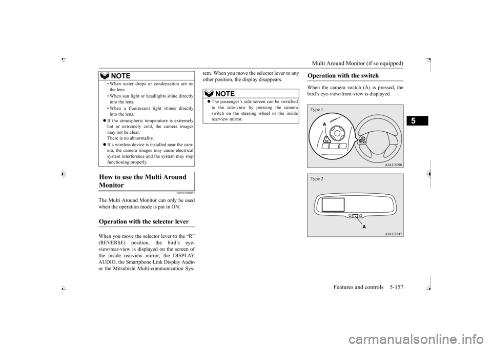
When the camera switch (A) is pressed, the bird’s eye-view/front
-view is displayed.
• When water drops or
condensation are on
the lens. • When sun light or he
adlights shine directly
into the lens. • When a fluorescent li
ght shines directly
into the lens.
If the atmospheric temperature is extremely hot or extremely cold, the camera images may not be clear.There is no abnormality. If a wireless device is installed near the cam- era, the camera images may cause electrical system interference and the system may stop functioning properly.
How to use the Multi Around Monitor
Operation with the selector lever
NOTE
NOTE
The passenger’s side sc
reen can be switched
to the side-view by pressing the camera switch on the steering wheel or the inside rearview mirror.
Operation with the switch
Type 1Type 2
BK0239700US.book 157 ページ 2016年6月16日 木曜日 午前10時58分
Page 239 of 521
Multi Around Monitor (if so equipped)
5
If the camera switch is pressed, the mode of Multi Around Monitor is
switched as follows.
Bird’s eye-view/Rear-view mode
Side-
view/Rear-view mode Bird’s eye-view/Rear-view mode
Side-
view/Rear-view mode
OFF
If the camera switch is
pressed, the mode of
Multi Around Monitor is switched, Bird’seye-view/Front-view mode
Side-
view/Front-view mode
OFF
N00587600033
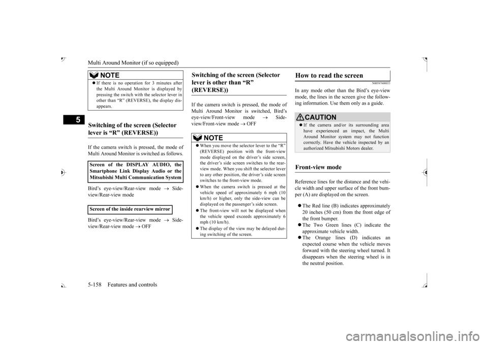
In any mode other than the Bird’s eye-view mode, the lines in the screen give the follow- ing information. Use them only as a guide. Reference lines for the distance and the vehi- cle width and upper surface of the front bum- per (A) are displayed on the screen. The Red line (B) indicates approximately 20 inches (50 cm) from the front edge ofthe front bumper. The Two Green lines (C) indicate the approximate ve
hicle width.
The Orange lines (D) indicates an expected course when the vehicle moves forward with the steering wheel turned. Itdisappears when the
steering wheel is in
the neutral position.
NOTE
If there is no operation for 3 minutes after the Multi Around Monitor is displayed bypressing the switch with the selector lever inother than “R” (REVERSE), the display dis- appears.
Switching of the screen (Selector lever is
Page 240 of 521
Multi Around Monitor (if so equipped)
Features and controls 5-159
5
The approximate distance from the vehi- cle body is as follows:
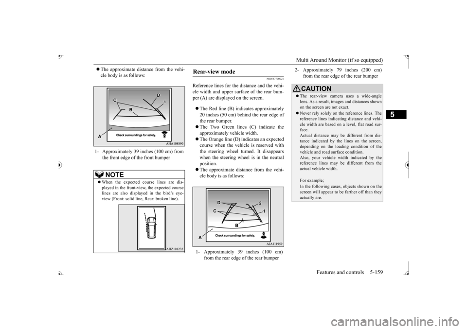
N00587700021
Reference lines for the distance and the vehi- cle width and upper surface of the rear bum- per (A) are displayed on the screen. The Red line (B) indicates approximately 20 inches (50 cm) behind the rear edge of the rear bumper. The Two Green lines (C) indicate the approximately vehicle width. The Orange line (D) indicates an expected course when the vehicle is reserved with the steering wheel turned. It disappears when the steering wheel is in the neutralposition. The approximate distance from the vehi- cle body is as follows:
1- Approximately 39 inches (100 cm) from
the front edge of the front bumperNOTE
When the expected course lines are dis- played in the front-vie
w, the expected course
lines are also displayed in the bird’s eye-view (Front: solid line
, Rear: broken line).
Rear-view mode
1- Approximately 39 inches (100 cm)
from the rear edge of the rear bumper
2- Approximately 79 inches (200 cm)
from the rear edge of the rear bumperCAUTION The rear-view camera uses a wide-angle lens. As a result, images and distances shown on the screen are not exact. Never rely solely on th
e reference lines. The
reference lines indicati
ng distance and vehi-
cle width are based on a level, flat road sur- face. Actual distance may be different from dis-tance indicated by the
lines on the screen,
depending on the loadi
ng condition of the
vehicle and road surface condition.Also, your vehicle wi
dth indicated by the
reference lines may be different from the actual vehicle width.For example;In the following cases, objects shown on thescreen will appear to
be farther off than they
actually are.
BK0239700US.book 159 ページ 2016年6月16日 木曜日 午前10時58分
Page 257 of 521
Multi Information display - Type 1 5-176 Features and controls
5
N00578600024
While driving, the momentary fuel consump- tion is shown with a bar graph. The “ ” mark in the momentary fuel gauge shows the average fuel consumption. When the momentary fuel consumption sur- passes the average fuel consumption, themomentary fuel consumption is displayed with a green bar graph. Be conscious of maintaining the momentaryfuel consumption above the average fuel con- sumption, it can help you drive with the better fuel consumption.
N00568701032
This indicator will be displayed when fuel-efficient driving is achieved.
N00578700038
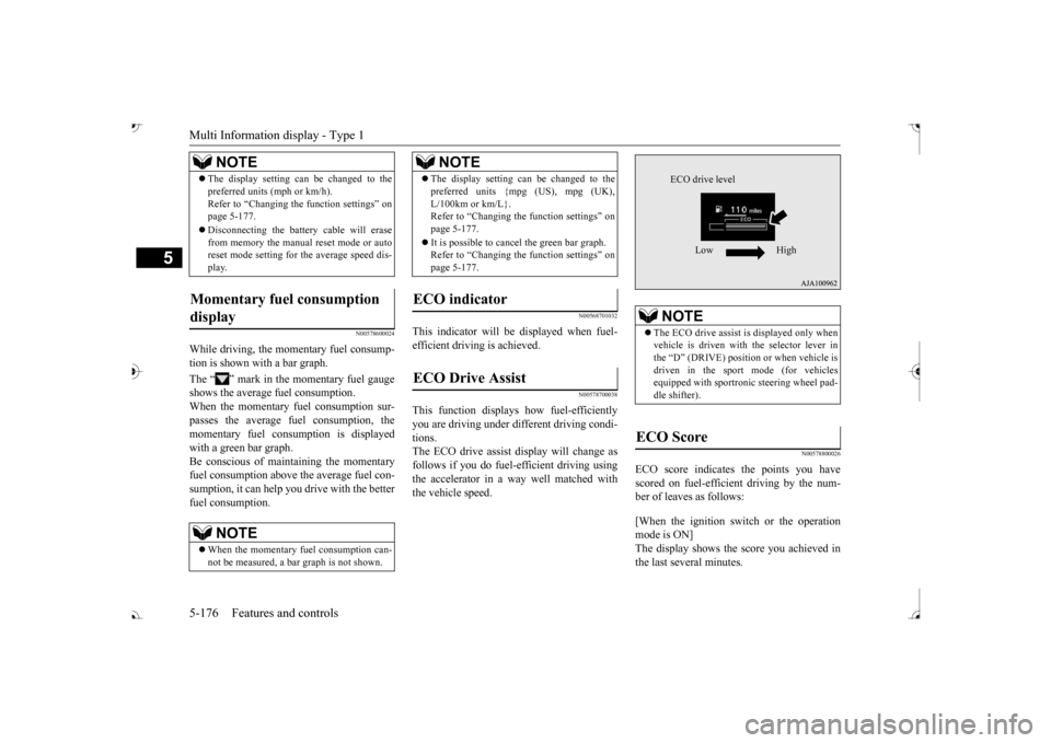
This function displays
how fuel-efficiently
you are driving under different driving condi- tions. The ECO drive assist display will change asfollows if you do fuel-efficient driving using the accelerator in a way well matched with the vehicle speed.
N00578800026
ECO score indicates the points you have scored on fuel-efficient driving by the num- ber of leaves as follows: [When the ignition switch or the operation mode is ON] The display shows the score you achieved in the last several minutes.
The display setting can be changed to the preferred units (mph or km/h).Refer to “Changing th
e function settings” on
page 5-177. Disconnecting the batt
ery cable will erase
from memory the manual reset mode or auto reset mode setting for the average speed dis- play.
Momentary fuel consumption display
NOTE
When the momentary fuel consumption can- not be measured, a ba
r graph is not shown.
NOTE
The display setting can be changed to the preferred units {mpg (US), mpg (UK),L/100km or km/L}.Refer to “Changing the
function settings” on
page 5-177. It is possible to cancel the green bar graph. Refer to “Changing the
function settings” on
page 5-177.
ECO indicator ECO Drive Assist
NOTE
NOTE
The ECO drive assist is displayed only when vehicle is driven with
the selector lever in
the “D” (DRIVE) positi
on or when vehicle is
driven in the sport mode (for vehicles equipped with sportroni
c steering wheel pad-
dle shifter).
ECO Score
ECO drive level
Low High
BK0239700US.book 176 ページ 2016年6月16日 木曜日 午前10時58分
Page 276 of 521
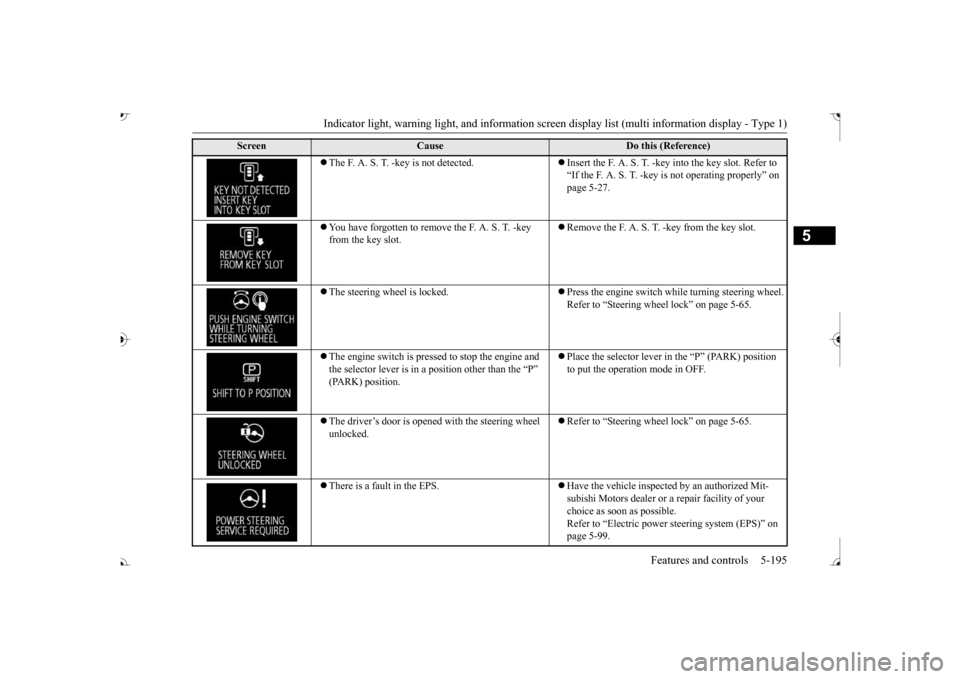
Indicator light, warning light, and information screen display list (multi information display - Type 1)
Features and controls 5-195
5
The F. A. S. T. -key is not detected.
Insert the F. A. S. T. -key into the key slot. Refer to “If the F. A. S. T. -key
is not operating properly” on
page 5-27.
You have forgotten to remove
the F. A. S. T. -key
from the key slot.
Remove the F. A. S. T.
-key from the key slot.
The steering wheel is locked.
Press the engine switch wh
ile turning steering wheel.
Refer to “Steering wheel lock” on page 5-65.
The engine switch is pre
ssed to stop the engine and
the selector lever is in a position other than the “P”
Place the selector lever in
the “P” (PARK) position
to put the operati
on mode in OFF.
The driver’s door is opened with the steering wheel unlocked.
Refer to “Steering wheel lock” on page 5-65.
There is a fault in the EPS.
Have the vehicle inspected by an authorized Mit- subishi Motors dealer or a
repair facility of your
choice as soon as possible. Refer to “Electric power
steering system (EPS)” on
page 5-99.
Screen
Cause
Do this (Reference)
BK0239700US.book 195 ページ 2016年6月16日 木曜日 午前10時58分