2017 MITSUBISHI OUTLANDER III fuses
[x] Cancel search: fusesPage 27 of 521
Modifications to and racing of your vehicle 3-6 General information
3
Modification of any onboard com- puter/control module, including repro-gramming, or replacing/adding chips to any onboard computer/control module
Review the Warranty and Maintenance Man- ual for further details
regarding warranty cov-
erage.
N00301701251
The installation of accessories, optional parts, etc., should only be performedwithin the limits prescribed by law, and in accordance with the guidelines and warn- ings contained within the documentsaccompanying this vehicle.
Only Mitsubishi Motors approved acces- sories should be fitted to your vehicle. Improper installation of electrical parts could cause a fire. Re
fer to the “Modifica-
tion/alterations to the electrical or fuelsystems” section with
in this owner’s man-
ual. Using a cellular phone or radio set inside the vehicle without an
external antenna
may cause electrical system interference, which could lead to unsafe vehicle opera- tion. Tires and wheels whic
h do not meet spec-
ifications must not be used. Refer to the “Specifications” section for information regard
ing wheel and tire
sizes.
Due to the large number of accessory and replacement parts provided by different man- ufacturers in the market, it is not always pos-sible for an authorized Mitsubishi Motors dealer to check whether the attachment or installation of a non-Mitsubishi Motors genu-ine parts affects the driving safety of your Mitsubishi-vehicle.
N00301800141
Mitsubishi Motors manu
factures high quality
vehicles with an emphasis on safety. It is important to consult an
authorized Mitsubishi
Motors dealer before
installation of any
accessory which may in
volve modification of
the electrical or fuel systems.
Installation of accessories
CAUTION Before any electrical or electronic accesso- ries are installed, cons
ult an authorized Mit-
subishi Motors dealer. Your vehicle is equipped with a diagnosis connector (data link connector) for checking and servicing the elec
tronic control system.
Mitsubishi Motors doe
s not recommend con-
necting a device other th
an the Scan Tool for
inspections and service to this connectorbecause an unexpected
problem could result.
In addition, malfuncti
ons caused by connect-
ing a device other than the Scan Tool maynot be covered under warranty.
WA R N I N G While driving, do not use a cellular phone in a way that hinder
s safe driving. Any-
thing, including cell
ular phone usage, that
distracts you from the safe operation ofyour vehicle incr
eases your risk of an acci-
dent. Refer to and follow al
l state and local laws
in your area regardi
ng cellular phone
usage while driving.
Important point! Modification/alterations to the electrical or fuel systems
CAUTION Please consult an authorized Mitsubishi Motors dealer concer
ning any such acces-
sory fitment or modification. If the wires interfere
with the vehicle body or
improper installation me
thods are used (pro-
tective fuses not included, etc.), electronic devices may be adversel
y affected, resulting
in a fire, vehicle dama
ge, or other accident.
BK0239700US.book 6 ページ 2016年6月16日 木曜日 午前10時58分
Page 454 of 521
9
Vehicle care and maintenanceService precautions ..........................................................................9-2 Catalytic converter ...........................................................................9-2 Engine hood .........
...........
...........
............
...........
.........
........
.........
.....9-3
View of the engine compartment .....................................................9-5 Engine oil and oil filter ....................................................................9-6 Engine coolant .................................................................................9-8Air cleaner filter ...............................................................................9-9 Automatic transaxle fluid (if so equipped) ..................................... 9-11 Continuously variable transmission
(CVT) fluid (if so equipped) . 9-11
Transfer oil (All-wheel drive models) ...........................................9-12 Rear axle oil (All-wheel drive models) .........................................9-12 Washer fluid ...................................................................................9-12Brake fluid .....................................................................................9-12 Battery ............................................................................................9-13 Tires ...............................................................................................9-15Brake pedal free play .....................................................................9-21 Parking brake lever stroke (if so equipped) ....................................9-22 Wiper blades ..................................................................................9-22Emission-control system maintenance ..........................................9-22 General maintenance .....................................................................9-23 For cold and snowy weather ..........................................................9-25Fusible links ...................................................................................9-25 Fuses ..............................................................................................9-25 Replacement of light bulbs ............................................................9-31Vehicle care precautions ................................................................9-39 Cleaning the inside of your vehicle .......
...........
...........
...........
.......9-40
Cleaning the outside of your vehicle .....
...........
...........
...........
.......9-41
BK0239700US.book 1 ページ 2016年6月16日 木曜日 午前10時58分
Page 478 of 521
For cold and snowy weather
Vehicle care and maintenance 9-25
9
N00942501124
The hood lock release mechanism and hood safety catch should be
checked, cleaned, and
oiled when needed for easy movement and to prevent rust and wear. Use Multipurpose Grease NLGI Grade 2 sp
aringly for all sliding
parts of the hood latc
h and release lever.
Work the grease into the hood lock mecha- nism until all the mo
vable surfaces are cov-
ered. Also, put a light coat of the same grease onthe safety catch wherever moving parts touch.
N00942600102
The ventilation slots in front of the wind-shield should be brus
hed clear after a heavy
snowfall so that the operation of the heating and ventilation systems
will not be impaired.
To prevent freezing of the weatherstripping on the doors, engine hood, etc., they should be treated with silicone grease. It is a good idea to carry a shovel or a short- handled spade in the vehicle during the win-ter so that you can clear away snow if you get stranded. A small hand-brush for sweeping snow off the vehicle a
nd a plastic scraper for
the windshield, side an
d rear window are also
useful.
N00942700291
The fusible links will melt to prevent a fire ifa large current attempts
to flow through cer-
tain electrical systems.In case of a melted fusible link, see your authorized Mitsubishi Motors dealer or a repair facility of your
choice for inspection
and replacement. For the fusible links, pl
ease refer to “Fuse
load capacities” on page 9-27.
N00942801954
To prevent damage to the electrical systemfrom short-circuiting
or overloading, each
individual circuit is e
quipped with a fuse. The
fuse blocks are located in the passenger com- partment and in the engine compartment.
Hood lock release mechanism and safety catch For cold and snowy weather Ventilation slots
Weatherstripping Additional equipment (For regions where snow is encoun- tered) Fusible links
WA R N I N G Fusible links must not be replaced by any other device. Failing to fit the correct fus-ible link may result in fire in the vehicle,property destruction and serious or fatal injuries at any time.
Fuses Fuse block location
BK0239700US.book 25 ページ 2016年6月16日 木曜日 午前10時58分
Page 479 of 521
Fuses 9-26 Vehicle care and maintenance
9
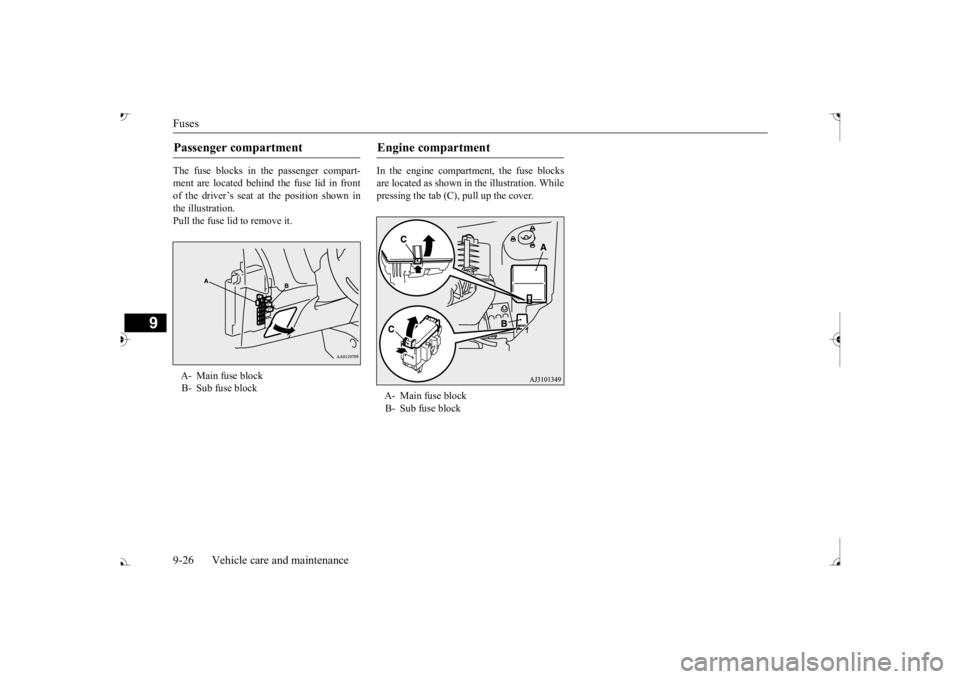
The fuse blocks in the passenger compart- ment are located behind the fuse lid in front of the driver’s seat at the position shown in the illustration.Pull the fuse lid to remove it.
In the engine compartment, the fuse blocks are located as shown in the illustration. While pressing the tab (C), pull up the cover.
Passenger compartment A- Main fuse block B- Sub fuse block
Engine compartment A- Main fuse block B- Sub fuse block
BK0239700US.book 26 ページ 2016年6月16日 木曜日 午前10時58分
Page 480 of 521
Fuses
Vehicle care and maintenance 9-27
9
N00954801427
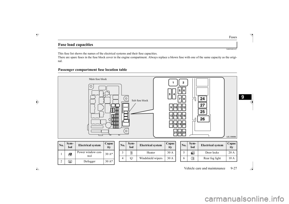
This fuse list shows the names of the elec
trical systems and their fuse capacities.
There are spare fuses in the fuse block cover in the engine compar
tment. Always replace a blown fu
se with one of the same capac
ity as the origi-
nal.Fuse load capacities Passenger compartment
fuse location table
Main fuse block
Sub fuse block
No.
Sym- bol
Electrical system
Capacity
1
Power window con-
trol
30 A*
2 Defogger 30 A*
3 Heater 30 A 4 Windshield wipers 30 ANo.
Sym- bol
Electrical system
Capacity
5 Door locks 20 A 6 Rear fog light 10 ANo.
Sym- bol
Electrical system
Capacity
BK0239700US.book 27 ページ 2016年6月16日 木曜日 午前10時58分
Page 481 of 521
Fuses 9-28 Vehicle care and maintenance
9
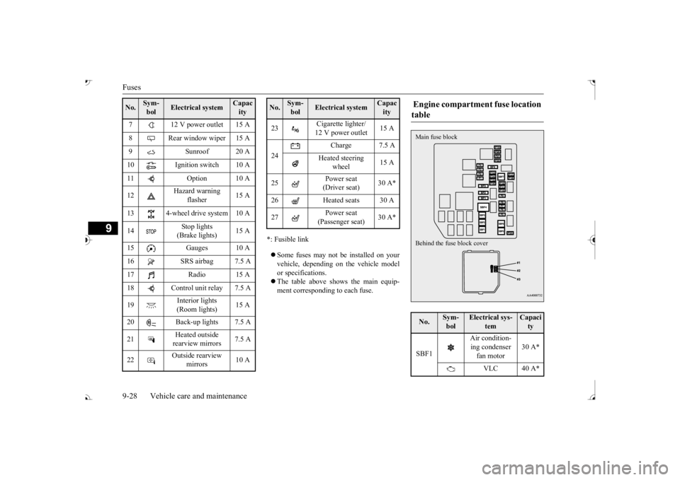
*: Fusible link Some fuses may not be installed on your vehicle, depending on
the vehicle model
or specifications. The table above show
s the main equip-
ment corresponding to each fuse.
7 12 V power outlet 15 A 8 Rear window wiper 15 A 9 Sunroof 20 A 10 Ignition switch 10 A11 Option 10 A 12
Hazard warning
flasher
15 A
13 4-wheel drive system 10 A 14
Stop lights (Brake lights)
15 A
15 Gauges 10 A 16 SRS airbag 7.5 A 17 Radio 15 A18 Control unit relay 7.5 A 19
Interior lights (Room lights)
15 A
20 Back-up lights 7.5 A 21
Heated outside rearview mirrors
7.5 A
22
Outside rearview
mirrors
10 A
No.
Sym- bol
Electrical system
Capacity
23
Cigarette lighter/ 12 V power outlet
15 A
24
Charge 7.5 A
Heated steering
wheel
15 A
25
Power seat (Driver seat)
30 A*
26 Heated seats 30 A 27
Power seat (Passenger seat)
No.
Sym- bol
Electrical system
Capacity
Engine compartment fuse location table No.
Sym- bol
Electrical sys-
tem
Capacity
SBF1
Air condition- ing condenser fan motor
30 A*
VLC 40 A*
Behind the fuse block cover Main fuse block
BK0239700US.book 28 ページ 2016年6月16日 木曜日 午前10時58分
Page 482 of 521

Fuses
Vehicle care and maintenance 9-29
9
*: Fusible link
SBF2 Starter 30 A* SBF3
Air condition- ing condenser fan motor
30 A*
SBF4
Radiator fan
motor
40 A*
SBF5
Anti-lock brak- ing system
40 A*
SBF6
Electric parking
brake
50 A*
SBF7
Anti-lock brak- ing system
30 A*
BF1 Power liftgate 30 A BF2
Audio system amplifier
30 A
BF3 IOD IOD 30 A BF4 Diesel 30 A F1
Automatic transaxle
20 A
F2 Wiper de-icer 15A F3
Electric parking
brake
7.5 A
F4
Daytime run- ning lights
10 A
No.
Sym- bol
Electrical sys-
tem
Capacity
F5 Front fog lights 15 A F6 Air conditioner 10 A F7
Headlight washer
20 A
F8 Security horn 20 A F9 Horn 10 A F10 ETV 15 AF11 Alternator 7.5 AF12 Engine 7.5 A F13
ENG/POWER 20 A Fuel line heater 25 A
F14 Fuel pump 15 A F15 Ignition coil 10 AF16 ENG/POWER 10 A F17
Headlight (high beam) (left)
10 A
F18
Headlight (high beam) (right)
10 A
No.
Sym- bol
Electrical sys-
tem
Capacity
F19
Head- light (low beam) (left)
LED 20 A
F20
Head- light (low beam) (right)
LED 20 A
F21
Head- light (low beam) (left)
Halo- gen
10 A
F22
Head- light (low beam) (right)
Halo- gen
10 A
F23
Battery current
sensor
7.5 A
#1 — Spare fuse 10 A #2 — Spare fuse 15 A #3 — Spare fuse 20 ANo.
Sym- bol
Electrical sys-
tem
Capacity
BK0239700US.book 29 ページ 2016年6月16日 木曜日 午前10時58分
Page 483 of 521
Fuses 9-30 Vehicle care and maintenance
9
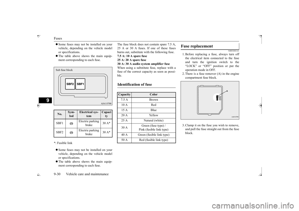
Some fuses may not be installed on your vehicle, depending on the vehicle modelor specifications. The table above shows the main equip- ment corresponding to each fuse.
*: Fusible link Some fuses may not be installed on your vehicle, depending on the vehicle model or specifications. The table above shows the main equip- ment corresponding to each fuse.
The fuse block does not contain spare 7.5 A, 25 A or 30 A fuses. If one of these fusesburns out, substitute w
ith the following fuse.
7.5 A: 10 A spare fuse 25 A: 20 A spare fuse30 A: 30 A audio system amplifier fuse When using a substitute
fuse, replace with a
fuse of the correct capa
city as soon as possi-
ble.
N00954901141
1. Before replacing a fuse, always turn off the electrical item
connected to the fuse
and turn the ignition switch to the“LOCK” or “OFF” position or put the operation mode in OFF. 2. There is a fuse remover (A) in the enginecompartment fuse block. 3. Clamp it on the fuse you wish to remove, and pull the fuse straight out from the fuseblock.
No.
Sym- bol
Electrical sys-
tem
Capacity
SBF1
Electric parking
brake
30 A*
SBF2
Electric parking
brake
30 A*
Sub fuse block
Identification of fuse Capacity
Color
7.5 A Brown 10 A Red 15 A Blue 20 A Yellow 25 A Natural (white) 30 A
Green (fuse type) / Pink (fusible link type)
40 A Green (fusible link type) 50 A Red (fusible link type)
Fuse replacement
BK0239700US.book 30 ページ 2016年6月16日 木曜日 午前10時58分