2017 MITSUBISHI OUTLANDER III ECU
[x] Cancel search: ECUPage 143 of 521
Outside rearview mirrors 5-62 Features and controls
5
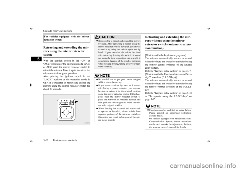
With the ignition switch in the “ON” or “ACC” position or the
operation mode in ON
or ACC, push the mirror retractor switch to retract the mirrors. Push it again to extend the mirrors to their original positions. After placing the ignition switch in the“LOCK” position or the operation mode in OFF, it is possible to
retract and extend the
mirrors using the mirror retractor switch forabout 30 seconds.
[Vehicles with the keyless entry system] The mirrors automatically retract or extend when the doors are locked or unlocked usingthe remote control switches of the keyless entry system. Refer to “Keyless entry system” on page 5-7. [Vehicles with the Free-hand Advanced Secu- rity Transmitter (F.A.S.T-key)]The mirrors automatically retract or extend when the doors are locked or unlocked using the remote control switches or the F.A.S.T-key. Refer to “Keyless entry system” on page 5-30 or “To operate using the F.A.S.T.-key” onpage 5-15.
For vehicles equipped with the mirror retractor switchRetracting and extending the mir- rors using the mirror retractor switch
CAUTION It is possible to retract and extend the mirrors by hand. After retracti
ng a mirror using the
mirror retractor switch, however, you shouldextend it by using the switch again, not by hand. If you extended the mirror by hand after retracting it using
the switch, it would
not properly lock in pos
ition. As a result, it
could move because of the wind or vibration while you are driving, taking away your rear-ward visibility.NOTE
Be careful not to get your hands trapped while a mirror is moving. If you move a mirror by hand or it moves after hitting a person or object, you may not be able to return it to its original positionusing the mirror retractor switch. If this hap- pens, push the mirror retractor switch to place the mirror in its
retracted position and
then push the switch again to return the mir- ror to its original position. When freezing has occurred and mirrors fail to operate as intended,
please refrain from
repeated pushing of the retractor switch asthis action can result in burn-out of the mir-ror motor circuits.
Retracting and extending the mir- rors without using the mirror retractor switch (automatic exten- sion function)
NOTE
Functions can be modified as stated below. Please consult an authorized Mitsubishi Motors dealer. On vehicles e
quipped with Mitsubishi Multi-
Communication System, screen operations can be used to make
the adjustment. Refer to
the separate owner’s manual for details.
BK0239700US.book 62 ページ 2016年6月16日 木曜日 午前10時58分
Page 144 of 521
Ignition switch
Features and controls 5-63
5
N00549301260
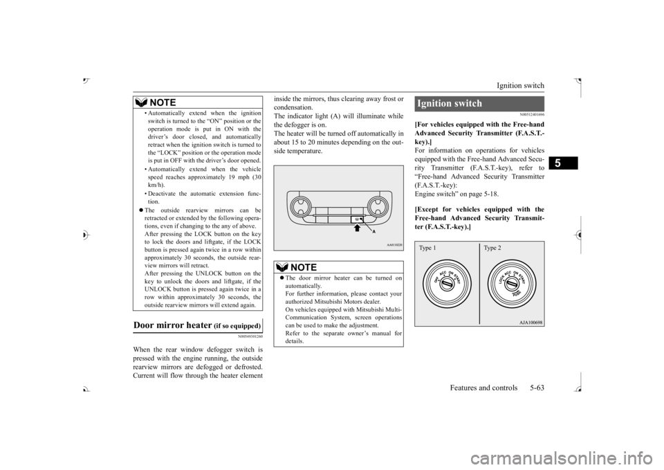
When the rear window defogger switch is pressed with the engine running, the outside rearview mirrors are defogged or defrosted. Current will flow thr
ough the heater element
inside the mirrors, thus clearing away frost or condensation.The indicator light (A) will illuminate while the defogger is on. The heater will be turned off automatically inabout 15 to 20 minutes depending on the out- side temperature.
N00512401696
[For vehicles equipped with the Free-handAdvanced Security Tr
ansmitter (F.A.S.T.-
key).]For information on operations for vehicles equipped with the Free-hand Advanced Secu- rity Transmitter (F.A
.S.T.-key), refer to
“Free-hand Advanced
Security Transmitter
(F.A.S.T.-key): Engine switch” on page 5-18. [Except for vehicles equipped with the Free-hand Advanced Security Transmit- ter (F.A.S.T.-key).]
• Automatically extend when the ignition switch is turned to the “ON” position or theoperation mode is put in ON with thedriver’s door closed, and automatically retract when the ignition switch is turned to the “LOCK” position or the operation modeis put in OFF with the driver’s door opened. • Automatically extend when the vehicle speed reaches approximately 19 mph (30 km/h). • Deactivate the automatic extension func- tion.
The outside rearvi
ew mirrors can be
retracted or extended
by the following opera-
tions, even if changing to the any of above.After pressing the LOCK
button on the key
to lock the doors and liftgate, if the LOCK button is pressed again twice in a row withinapproximately 30 seconds
, the outside rear-
view mirrors will retract. After pressing the
UNLOCK button on the
key to unlock the doors and liftgate, if the UNLOCK button is pressed again twice in a row within approximately 30 seconds, theoutside rearview mirro
rs will extend again.
Door mirror heater
(if so equipped)
NOTE
The door mirror heater can be turned on automatically.For further informati
on, please contact your
authorized Mitsubishi Motors dealer. On vehicles equipped
with Mitsubishi Multi-
Communication System, screen operations can be used to ma
ke the adjustment.
Refer to the separate
owner’s manual for
details.
Ignition switch Type 1 Type 2
BK0239700US.book 63 ページ 2016年6月16日 木曜日 午前10時58分
Page 146 of 521
Steering wheel lock (if so equipped)
Features and controls 5-65
5
When removing the key, first set the selector lever to the “P” (PARK) position, and push the key in at the “ACC” position and keep it depressed until it is turned to the “LOCK”position, and remove it.
N00512501235
[For vehicles equipped with the Free-handAdvanced Security Transmitter (F.A.S.T.- key).] For information on operations for vehiclesequipped with the Free-hand Advanced Secu- rity Transmitter (F.A.S.T.-key), refer to “Free-hand Advanced Se
curity Transmitter
(F.A.S.T.-key): Steering wheel lock” on page 5-24. [Except for vehicles equipped with the Free-hand Advanced Security Transmit-
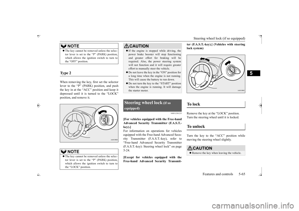
ter (F.A.S.T.-key).] (Vehicles with steering lock system) Remove the key at the “LOCK” position. Turn the steering wheel until it is locked. Turn the key to the “ACC” position while moving the steeri
ng wheel slightly.
NOTE
The key cannot be rem
oved unless the selec-
tor lever is set to the “P” (PARK) position,which allows the ignition switch to turn tothe “OFF” position.
Ty p e 2
NOTE
The key cannot be rem
oved unless the selec-
tor lever is set to the “P” (PARK) position,which allows the ignition switch to turn to the “LOCK” position.
CAUTION If the engine is stoppe
d while driving, the
power brake booster will stop functioningand greater effort for braking will berequired. Also, the power steering system will not function and it
will require greater
effort to manually steer the vehicle. Do not leave the key in
the “ON” position for
a long time when the engine is not running.This will cause the battery to run down. Do not turn the key to the “START” position when the engine is ru
nning. It will damage
the starter motor.
Steering wheel lock
(if so
equipped)
To unlock
CAUTION Remove the key when leaving the vehicle.
BK0239700US.book 65 ページ 2016年6月16日 木曜日 午前10時58分
Page 147 of 521
![MITSUBISHI OUTLANDER III 2017 Owners Manual Starting the engine 5-66 Features and controls
5
N00512601845
[For vehicles equipped with the Free-hand Advanced Security Transmitter (F.A.S.T.-key).] For information on operation for vehicles equippe MITSUBISHI OUTLANDER III 2017 Owners Manual Starting the engine 5-66 Features and controls
5
N00512601845
[For vehicles equipped with the Free-hand Advanced Security Transmitter (F.A.S.T.-key).] For information on operation for vehicles equippe](/manual-img/19/58146/w960_58146-146.png)
Starting the engine 5-66 Features and controls
5
N00512601845
[For vehicles equipped with the Free-hand Advanced Security Transmitter (F.A.S.T.-key).] For information on operation for vehicles equipped with the Free-hand Advanced Secu-rity Transmitter (F.A.S.T.-key), refer to “Free-hand Advanced Se
curity Transmitter
(F.A.S.T.-key): Starting” on page 5-13. [Except for vehicles equipped with the Free-hand Advanced Security Transmit- ter (F.A.S.T.-key).]
Do not operate the starter motor continu- ously for longer than 15 seconds as this could run the battery
down or damage the
starter motor. If the engine does not start,turn the ignition switch back to the “OFF” or “LOCK” position, wait a few seconds, and then try again. Trying repeatedly withthe engine or starter motor still turning will damage the starter mechanism. If the engine will not
start because the bat-
tery is weak or discharged, refer to “Jump-starting the engine” (on page 8-2)for instructions. A longer warm up period will only con- sume extra fuel. The engine is warmed upenough for driving when the bar graph of engine coolant temper
ature display starts
to move or the low coolant temperatureindicator goes out. Refer to “Engine cool- ant temperature display” on page 5-171 or “Low coolant temper
ature indicator” on
page 5-215.
This model is equipped with an electronically controlled fuel injection system. This is a sys- tem that automatically controls fuel injection.There is usually no need to depress the accel- erator pedal when starting the engine. The starter should not be run for more than 15seconds at a time. To prevent battery drain, wait a few seconds between attempts to restart the engine. 1. Make sure all occupants are properly seated with seat belts fastened. 2. Insert the ignition key. 3. Press and hold the brake pedal down withyour right foot. 4. Make sure the selector
lever is in the “P”
NOTE
If the front wheels are turned, the anti-theft lock may sometimes make it difficult to turnthe key from “LOCK” to “ACC”. Firmlyturn the steering wheel to the left or to the right as you turn the key.
Starting the engine
Tips for starting
WA R N I N G Never run the engine in
a closed or poorly
ventilated area any longer than is needed to move your vehicle out of the area. Car- bon monoxide gas, which is odorless andextremely poisonous, could build up and cause serious injury or death.
CAUTION Do not push-start the vehicle.Do not run the engine at high rpms or drive at high speeds until
the engine has had a
chance to warm up. Release the ignition sw
itch as soon as the
engine starts. Otherwis
e, the starter motor
will be damaged
Starting the engine
BK0239700US.book 66 ページ 2016年6月16日 木曜日 午前10時58分
Page 154 of 521
Automatic transaxle (if so equipped)
Features and controls 5-73
5
N00538801180
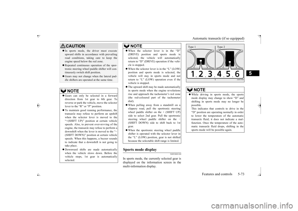
In sports mode, the currently selected gear is displayed on the information screen in the multi-information display.
CAUTION In sports mode, the driver must execute upward shifts in accordance with prevailingroad conditions, taking care to keep theengine speed below the red zone. Repeated continuous ope
ration of the spor-
tronic steering wheel pa
ddle shifter will con-
tinuously switch shift position. Gears may not change when the lateral pad- dle shifters are operate
d at the same time.
NOTE
Gears can only be selected in a forward direction from 1st gear to 6th gear. Toreverse or park the vehi
cle, move the selector
lever to the “R” or “P” position. To maintain good running performance, the transaxle may refuse to perform an upshift when the selector lever is moved to the“+(SHIFT UP)” positi
on at certain vehicle
speeds. Also, to prevent over-revving of the engine, the transaxle may refuse to perform adownshift when the lever is moved to the “
−
(SHIFT DOWN)” positi
on at certain vehicle
speeds. When this happens, a buzzer soundsto indicate that a dow
nshift is not going to
take place. Downward shifts are made automatically when the vehicle slow
s down. Before the
vehicle stops, 1st gear
is automatically
selected.
When the selector lever is in the “D”selected, the vehicle will automaticallyreturn to “D” (DRIVE)
operation if the vehi-
cle is stopped. When the selector lever is in the
Page 173 of 521
Service brake 5-92 Features and controls
5
N00517500275
Overuse of the brake can cause weakening, resulting in poor brake response and prema- ture wear of the brake pads. When driving down a long or steep hill, useengine braking
by downshifting.
N00517600364
Your vehicle is equipped with power brakes for more braking force with less brake pedal effort.Your brakes are designed to operate at full capacity, even if the power assist is not being used.If the power assist is not being used, the effort needed to press the brake pedal is greater. If you should lose the power assist for somereason, the brakes will still work. If the power brake unit or either of the two brake hydraulic systems stops working prop-erly, the rest of the brake system will still work, but the vehicle will not slow down as quickly.You will know this has happened if you find you need to press the brake down farther, or harder when slowing down or stopping, or ifthe brake warning light and the warning dis- play in the multi-information display come on.
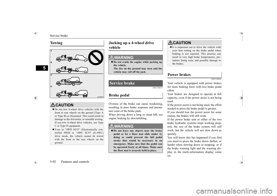
To w i n g
CAUTION Do not tow 4-wheel drive vehicles with the front or rear wheels on the ground (Type A or Type B) as illustrate
d. This could result in
damage to the drivetrain, or unstable towing.If you tow 4-wheel drive vehicles, use TypeC or Type D equipment. Even in “4WD ECO” (Electronically con- trolled 4WD) or “AWC ECO” (S-AWC) drive mode, the vehicle cannot be towed with the front or the rear wheels on theground.
Jacking up a 4-wheel drive vehicle
WA R N I N G Do not crank the engine while jacking up the vehicle. The tire on the ground may turn and thevehicle may roll off the jack.
Service brake Brake pedal
WA R N I N G Do not leave any objects near the brake pedal or let a floor mat slide under it;doing so could prevent the full pedal stroke that would be necessary in an emergency. Make sure that the pedal canbe operated freely at all times. Make sure the floor mat is securely held in place.
CAUTION It is important not to drive the vehicle with your foot resting on the brake pedal whenbraking is not required.
This practice can
result in very high brake temperatures, pre- mature lining wear, a
nd possible damage to
the brakes.
Power brakes
BK0239700US.book 92 ページ 2016年6月16日 木曜日 午前10時58分
Page 227 of 521

Tire pressure monitoring system 5-146 Features and controls
5
N00584300026
In case that 2 sets of tire inflation pressure sensor ID are registered in the receiver, the valid tire ID set can be changed by following procedure. [For vehicles equipped
with color liquid crys-
tal display meter] 1. Operate the multi information display switch to switch the information screen to the menu screen.Refer to “Multi in
formation display
switch” on page 5-167. Refer to “Changing the function settings”on page 5-177. 2. Lightly press the multi information dis- play switch to select “ ” (tire ID set change).
3. Hold down the multi information display switch for about 3 seconds or more. Thesetting changes to the selected tire ID set. 4. The valid tire ID se
t is changed, and the
number of the tire pressure monitoring system (TPMS) SET in
dicator is changed.
[For vehicles equipped
with mono-color liq-
uid crystal display meter] 1. Transit the display by multi information display switch until th
e tire pressure mon-
itoring system (TPMS) SET indicator isdisplayed.
2. Hold down the multi information display switch for 10 seconds or more. (A beep isheard.) (Although the reset execution starts at holding down the switch for 3 seconds,keep holding down the switch continu- ously.) 3. The valid tire ID set is changed, and the number of the tire
pressure monitoring
system (TPMS) SET i
ndicator is changed.
CAUTIONThe use of non-genuine wheels will prevent the proper fit of the tire inflation pressuresensors, resulting air
leakage or damage of
the sensors.
Tire ID set change
NOTE
Each time this procedure is done, the tire ID set is changed. (1 - 2 - 1 - 2 …) only 1 set of ID is registered.
NOTE
Each time this procedure is done, the tire ID set is changed. (1 - 2 - 1 - 2 …) only 1 set of ID is registered.
BK0239700US.book 146 ページ 2016年6月16日 木曜日 午前10時58分
Page 233 of 521
Rear-view camera (if so equipped) 5-152 Features and controls
5
When the selector lever is shifted out of the “R” (REVERSE) position, the rear-viewimage will go off.
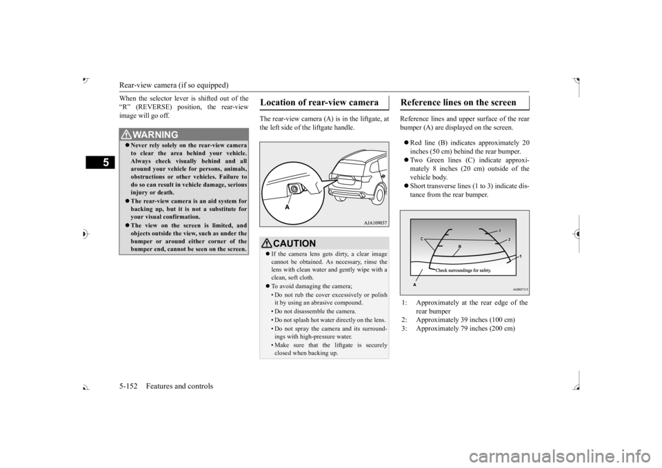
The rear-view camera (A) is in the liftgate, at the left side of the liftgate handle.
Reference lines and uppe
r surface of the rear
bumper (A) are displayed on the screen. Red line (B) indicates approximately 20 inches (50 cm) behind the rear bumper. Two Green lines (C) indicate approxi- mately 8 inches (20 cm) outside of the vehicle body. Short transverse lines (1
to 3) indicate dis-
tance from the rear bumper.
WA R N I N G Never rely solely on the rear-view camera to clear the area behind your vehicle.Always check visua
lly behind and all
around your vehicle fo
r persons, animals,
obstructions or other vehicles. Failure todo so can result in
vehicle damage, serious
injury or death. The rear-view camera is an aid system for backing up, but it is not a substitute for your visual confirmation. The view on the scre
en is limited, and
objects outside the view, such as under thebumper or around ei
ther corner of the
bumper end, cannot be seen on the screen.
Location of rear-view camera
CAUTION If the camera lens gets
dirty, a clear image
cannot be obtained. As necessary, rinse the lens with clean water and gently wipe with a clean, soft cloth. To avoid damaging the camera;• Do not rub the cover excessively or polish it by using an abrasive compound. • Do not disassemble the camera.• Do not splash hot wate
r directly on the lens.
• Do not spray the camera and its surround- ings with high-pressure water.• Make sure that the liftgate is securelyclosed when backing up.
Reference lines on the screen
1: Approximately at the rear edge of the
rear bumper
2: Approximately 39 inches (100 cm) 3: Approximately 79 inches (200 cm)
BK0239700US.book 152 ページ 2016年6月16日 木曜日 午前10時58分