2017 MITSUBISHI L200 wheel
[x] Cancel search: wheelPage 87 of 426
WARNINGlWe recommend work around and on the
side airbags and curtain airbags system to
be done by a MITSUBISHI MOTORS
Authorized Service Point.SRS warning lamp
E00407802963
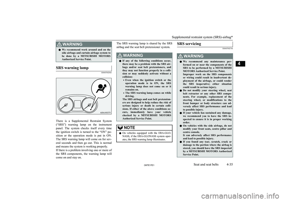
There is a Supplemental Restraint System
(“SRS”) warning lamp on the instrument panel. The system checks itself every time
the ignition switch is turned to the “ON” po- sition or the operation mode is put in ON.
The SRS warning lamp will come on for sev- eral seconds and then go out. This is normal and means the system is working properly.
If there is a problem involving one or more of
the SRS components, the warning lamp will
come on and stay on.
The SRS warning lamp is shared by the SRS
airbag and the seat belt pretensioner system.WARNINGl If any of the following conditions occur,
there may be a problem with the SRS air- bags and/or seat belt pretensioners, and
they may not function properly in a colli- sion or may suddenly activate without a
collision:
• Even when the ignition switch or the
operation mode is in ON, the SRS warning lamp does not come on or it
remains on.
• The SRS warning lamp comes on while
driving.
The SRS airbags and seat belt pretension- ers are designed to help reduce the risk of
serious injury or death in certain colli- sions. If either of the above conditions oc-
curs, immediately have your vehicle checked by a MITSUBISHI MOTORS
Authorized Service Point.NOTEl On vehicles equipped with the ERA-GLO-
NASS, if the ERA-GLONASS system oper- ates, the SRS warning lamp illuminates.SRS servicing
E00407902746
WARNINGl We recommend any maintenance per-
formed on or near the components of the
SRS to be performed by a MITSUBISHI
MOTORS Authorized Service Point.
Improper work on the SRS components or wiring could result in inadvertent de-
ployment of the airbags, or could render
the SRS inoperative; either situation could result in serious injury.
l Do not modify your steering wheel, seat
belt retractor or any other SRS compo-
nents. For example, replacement of the
steering wheel, or modifications to the
front bumper or body structure can ad- versely affect SRS performance and lead
to possible injury.
l If your vehicle has sustained any damage,
we recommend you to have the SRS in- spected to ensure it is in proper workingorder.
l On vehicles with the side airbags, do not
modify your front seats, centre pillar and centre console.
It can adversely affect SRS performance
and lead to possible injury.
l If you found any tear, scratch, crack or
damage to the portion where the airbag is stored, you should have the SRS inspected
by a MITSUBISHI MOTORS Authorized
Service Point.
Supplemental restraint system (SRS)-airbag*
4-35OKTE17E1Seat and seat belts4
Page 116 of 426

NOTElOn vehicles equipped with heated mirrors,
when the rear window demister switch is
pressed, the outside rear-view mirrors are defogged or defrosted. Refer to “Heated mir-
ror*” on page 6-12.
l The demister switch is not to melt snow but
to clear mist. Remove snow before use of the demister switch.
l To avoid unnecessary discharge of the bat-
tery, do not use the rear window demister during starting of the engine or when the en-
gine is not running. Turn the demister off
immediately after the window is clear.
l When cleaning the inside of the rear win-
dow, use a soft cloth and wipe gently along
the heater wires, being careful not to damage
the wires.
l Do not allow objects to touch the inside of
the rear window glass, damaged or broken wires may result.
Customizing the automatic
rear window demister (Vehi-cles equipped with the rear
window demister switch - Type 2)
Function can be changed as desired, as stated below.
l Enable automatic rear window demister
If the outside air temperature drops be-
low approx. 3 °C (37 °F), the rear win-
dow demister operates once automatical-
ly after the engine starts.
The heated mirrors will also operate once automatically at the same time.
l Disable automatic rear window demister
The rear window demister does not op-
erate automatically.
The heated mirrors will not operate auto- matically as well.
l Setting change method
Hold down the rear window demister
switch for about 10 seconds or more. • When the setting is changed from ena-
ble to disable:
3 sounds are emitted and the indica- tion lamp flashes 3 times.
• When the setting is changed from dis-
able to enable:
2 sounds are emitted and the indica- tion lamp flashes 3 times.NOTEl The factory setting is “Disable automatic
rear window demister”.Horn switch
E00508001823
Press the steering wheel on or around the
“
” mark.
Horn switch
5-28OKTE17E1Instruments and controls5 Type 1 Type 2
Page 117 of 426

Economical driving............................................................................. 6-02
Driving, alcohol and drugs.................................................................. 6-02
Safe driving techniques....................................................................... 6-03
Running-in recommendations............................................................. 6-04 Parking brake...................................................................................... 6-05
Parking................................................................................................ 6-06
Steering wheel height and reach adjustment....................................... 6-07
Inside rear-view mirror....................................................................... 6-08 Outside rear-view mirrors................................................................... 6-09
Ignition switch*...................................................................................6-13 Engine switch*.................................................................................... 6-14
Steering wheel lock............................................................................. 6-16
Starting and stopping the engine......................................................... 6-17
Diesel particulate filter (DPF)............................................................. 6-21 Turbocharger operation*..................................................................... 6-22Auto Stop & Go (AS&G) system*..................................................... 6-23
Manual transmission*......................................................................... 6-27 Automatic transmission Sports Mode 5A/T........................................6-28Easy select 4WD*............................................................................... 6-35
Super select 4WD II*.......................................................................... 6-40
Rear differential lock*........................................................................ 6-45 4-wheel drive operation*.................................................................... 6-49
Inspection and maintenance following rough road operation............. 6-52
Cautions on handling of 4-wheel drive vehicles................................. 6-52
Braking................................................................................................ 6-53
Hill start assist..................................................................................... 6-55
Brake assist system............................................................................. 6-56
Emergency stop signal system*.......................................................... 6-56
Anti-lock brake system (ABS)............................................................ 6-57Power steering system.........................................................................6-59
Active Stability & Traction Control (ASTC)*....................................6-59
Trailer Stability Assist (TSA)............................................................. 6-63 Cruise control*.................................................................................... 6-63
Speed Limiter...................................................................................... 6-69
Lane Departure Warning (LDW)*...................................................... 6-76
Rear-view camera*............................................................................. 6-79
Cargo loads......................................................................................... 6-83Trailer towing......................................................................................6-83Starting and driving
OKTE17E16
Page 122 of 426

To apply
1-Firmly depress and hold the brake pedal,
then pull the lever up without pushing
the button at the end of hand grip.
CAUTIONl When you intend to apply the parking brake,
firmly press the brake pedal to bring the ve-hicle to a complete stop before pulling theparking brake lever.
Pulling the parking brake lever with the ve- hicle moving could make the rear wheels
lock up, thereby making the vehicle unsta- ble. It could also make the parking brake
malfunction.NOTEl Apply sufficient force to the parking brake
lever to hold the vehicle stationary after the foot brake is released.NOTEl If the parking brake does not hold the vehi-
cle stationary after the foot brake is released,
have your vehicle checked immediately.
To release
1- Firmly depress and hold the brake pedal,
then pull the lever up slightly.
2- Push the button at the end of hand grip.
3- Lower the lever fully.
CAUTIONl Before driving, be sure that the parking
brake is fully released and brake warning
lamp is off.
If a vehicle is driven without releasing the
parking brake, the brake will be overheated, resulting in ineffective braking and possible
brake failure.CAUTIONl If the brake warning lamp does not extin-
guish when the parking brake is fully re- leased, the brake system may be abnormal.
Have your vehicle checked immediately.
For details, refer to “Brake warning lamp” on page 5-15.NOTEl To prevent the parking brake from being re-
leased unintentionally, the lever must be
pulled up slightly before it can be pushed down. Simply pressing the button does not
enable the lever to be pushed down.Parking
E00600602704
To park the vehicle, fully engage the parkingbrake, and then move the gearshift lever to 1 st
or “R” (Reverse) position for vehicles equip-
ped with M/T, or set the selector lever to “P”
(PARK) position for vehicles equipped with
A/T.
Parking on a hill
To prevent the vehicle from rolling, follow these procedures:
Parking
6-06OKTE17E1Starting and driving6
Page 123 of 426

Parking on a downhill slope
Turn the front wheels towards the kerb and
move the vehicle forward until the kerb side
wheel gently touches the kerb.
On vehicles equipped with M/T, apply the
parking brake and place the gearshift lever into the “R” (Reverse) position.
On vehicles equipped with A/T, apply the
parking brake and place the selector lever in-
to the “P” (PARK) position.
If necessary, apply chocks to wheels.
Parking on an uphill slope Turn the front wheels away from the kerb
and
move the vehicle back until the kerb side
wheel gently touches the kerb.
On vehicles equipped with M/T, apply the
parking brake and place the gearshift lever
into the 1 st
position.
On vehicles equipped with A/T, apply the
parking brake and place the selector lever in- to the “P” (PARK) position.
If necessary, apply chocks to wheels. NOTE
l
If
your vehicle is equipped with A/T, be sure
to apply the parking brake before moving se-
lector lever to the “P” (PARK) position. If
you move selector lever to the “P” (PARK) position before applying the parking brake,
it may be difficult to disengage selector lev- er from the “P” (PARK) position when next
you drive the vehicle, requiring application
of a strong force the selector lever to move
from the “P” (PARK) position. Parking with the engine run-
ning Never leave the engine running while you
take
a short sleep/rest. Also, never leave the
engine running in a closed or poorly ventila-
ted place. WARNING
l
Leaving
the engine running risks injury
or death from accidentally moving the
gearshift lever (with M/T) or the selector
lever (with A/T) or the accumulation of toxic exhaust fumes on the passenger
compartment. Where you park
WARNING
l
Do
not park your vehicle in areas where
combustible materials such as dry grass
or leaves can come in contact with a hot exhaust, since a fire could occur. When leaving the vehicle
Always carry the key and lock all doors when
leaving the vehicle unattended.
Always
try to park your vehicle in a well lit
area. Steering wheel height and
reach adjustment E00600701708
1. Release
the lever while holding the steering wheel up.
2. Adjust the steering wheel to the desired position.
3. Securely lock the steering wheel by pull- ing the lever fully upward.
Steering wheel height and reach adjustment
6-07
OKTE17E1 Starting and driving 6
Page 124 of 426

A- LockedB- Release
*: Vehicles equipped with the reach adjust- ment
WARNINGl Do not attempt to adjust the steering
wheel while you are driving the vehicle.Inside rear-view mirror
E00600802126
Adjust the rear-view mirror only after mak-
ing any seat adjustments so you have a clear
view to the rear of the vehicle.WARNINGl Do not attempt to adjust the rear-view
mirror while driving. This can be danger-
ous.
Always adjust the mirror before driving.
Adjust the rear-view mirror to maximize the
view through the rear window.
To adjust the vertical mirror
position
It is possible to move the mirror up and down
to adjust its position.
To adjust the mirror position
It is possible to move the mirror up/down and left/right to adjust its position.
Inside rear-view mirror
6-08OKTE17E1Starting and driving6Type 1
Type 2 Type 2
Type 1
Page 129 of 426

NOTElThe heater mirrors can be turned on auto-
matically.
For further information, we recommend you to consult a MITSUBISHI MOTORS Au-
thorized Service Point.Ignition switch*
E00601403302
LOCK
The engine is stopped and the steering wheel
locked. The key can only be inserted and re- moved in this position.
ACC
The engine is stopped, but the audio system
and other electric devices can be operated.
ON
All the vehicle’s electrical devices can be op-
erated.
START
The starter motor operates. After the engine has started, release the key and it will auto-
matically return to the “ON” position.
NOTEl If your vehicle is equipped with an electron-
ic immobilizer.
To start the engine, the ID code transmitted
by the transponder inside the key must match the code registered in the immobilizer
computer.
Refer to “Electronic immobilizer (Anti-theft starting system)” on page 3-03.To remove the key
E00620401538
For vehicles equipped with a M/T, when re-
moving the key, push the key in at the
“ACC” position and keep it depressed until it
is turned to the “LOCK” position and remove it.
For vehicles equipped with A/T, when re-
moving the key, first set the selector lever to
the “P” (PARK) position, and push the key in at the “ACC” position and keep it depressed
until it is turned to the “LOCK” position, and
remove it.CAUTIONl Do not remove the ignition key from the ig-
nition switch while driving. The steeringwheel will be locked, causing loss of con-
trol.
l If the engine is stopped while driving, the
brake servomechanism will cease to function and braking efficiency will deteriorate. Also,
the power steering system will not function
and it will require greater manual effort to
operate the steering.
Ignition switch*
6-13OKTE17E1Starting and driving6
Page 131 of 426

All vehicle’s electrical devices can be operat-ed.
The indication lamp on the engine switch il-
luminates green. The indication lamp turns
off when the engine is running.NOTEl Your vehicle is equipped with an electronic
immobilizer..
To start the engine, the ID code transmitted
by the transponder inside the key must match the code registered in the immobilizer
computer. Refer to “Electronic immobilizer
(Anti-theft starting system)” on page 3-03.Changing the operation mode
E00631901142
If you press the engine switch without de-
pressing the brake pedal (A/T) or the clutch
pedal (M/T), you can change the operation
mode in the order of OFF, ACC, ON, OFF.
CAUTIONl When the engine is not running, put the op-
eration mode in OFF. Leaving the operation mode in ON or ACC for a long time when
the engine is not running may cause the bat- tery to be discharged, making it impossible
to start the engine, lock and unlock the steer- ing wheel.
l When the battery is disconnected, the cur-
rent operation mode is memorized. After re- connecting the battery, the memorized modeis selected automatically. Before disconnect-
ing the battery for repair or replacement,
make sure to put the operation mode in OFF. Be careful if you are not sure which opera-
tion mode the vehicle is in when the battery
is run down.
l The operation mode cannot be changed from
OFF to ACC or ON if the keyless operation
key is not detected to be in the vehicle. Refer
to “Keyless operation system: Operating range for starting the engine and changing
the operation mode” on page 3-09.
l When there is the keyless operation key in
the vehicle and the operation mode isn’t
change, the keyless operation key may have worn out.ACC power auto-cutout func-
tion
E00632801151
After about 30 minutes has elapsed with the
operation mode in ACC, the function auto-
matically cuts out the power for the audio system and other electric devices that can be
operated with that position. (only that driv- er’s door has closed and the selector lever in
the “P” (PARK) position)
When you open driver’s door or the engine
switch operate again, the power is supplied
again.
NOTEl When ACC power supply automatic stop,
the steering wheel can’t lock and you can’t lock and unlock the doors by the keyless en-
try key and keyless operation key.
l It is possible to modify functions as follows:
• The time until the power cuts out can be
changed to approximately 60 minutes.
• The ACC power auto-cutout function can
be deactivated.
For details, we recommend you to consult
a MITSUBISHI MOTORS Authorized
Service Point.
Engine switch*
6-15OKTE17E1Starting and driving6