2017 MERCEDES-BENZ S-Class MAYBACH transmission
[x] Cancel search: transmissionPage 341 of 382

The battery must be connected and charged.
Otherwise, you:
Rcannot turn the SmartKey to position2in the
ignition lock
Rcannot release the electric parking brake
Rcannot shift the automatic transmission to
position N
Disarm the automatic locking feature before the vehicle is towed (
Ypage 84). You could other-
wise be locked out when pushing or towing the
vehicle.
If the vehicle is in a dangerous area, it can be
towed out of that area with both axles on the
ground. In this case, the towing distance must
not be greater than 165 ft (50 m)and must not
exceed a towing speed of 6 mph (10 km/h). For
longer distances, have the vehicle loaded and
transported.
Installing/removing the towing eye
Installing the towing eye
GWARNING
The exhaust tail pipe may be very hot. There is
a risk of burns when removing the rear cover.
Do not touch the exhaust pipe. Take particular
care when removing the rear cover.
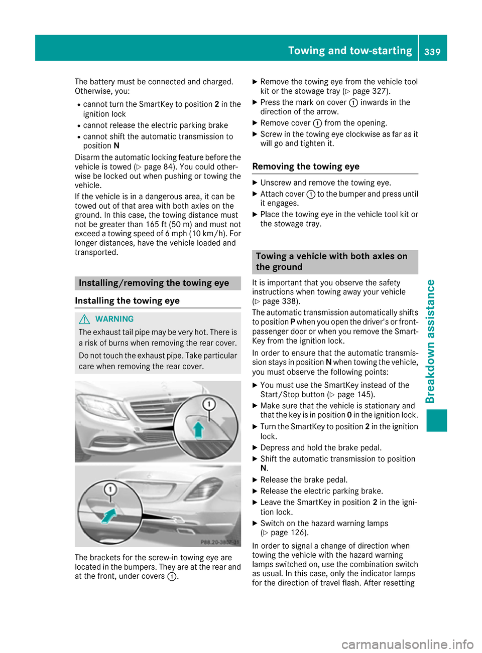
The brackets for the screw-in towing eye are
located in the bumpers. They are at the rear and
at the front, under covers :.
XRemove the towing eye from the vehicle tool
kit or the stowage tray (Ypage 327).
XPress the mark on cover:inwards in the
direction of the arrow.
XRemove cover :from the opening.
XScrew in the towing eye clockwise as far as it
will go and tighten it.
Removing the towing eye
XUnscrew and remove the towing eye.
XAttach cover :to the bumper and press until
it engages.
XPlace the towing eye in the vehicle tool kit or
the stowage tray.
Towing a vehicle with both axles on
the ground
It is important that you observe the safety
instructions when towing away your vehicle
(
Ypage 338).
The automatic transmission automatically shifts
to position Pwhen you open the driver's or front-
passenger door or when you remove the Smart-
Key from the ignition lock.
In order to ensure that the automatic transmis-
sion stays in position Nwhen towing the vehicle,
you must observe the following points:
XYou must use the SmartKey instead of the
Start/Stop button (Ypage 145).
XMake sure that the vehicle is stationary and
that the key is in position 0in the ignition lock.
XTurn the SmartKey to position 2in the ignition
lock.
XDepress and hold the brake pedal.
XShift the automatic transmission to position
N .
XRelease the brake pedal.
XRelease the electric parking brake.
XLeave the SmartKey in position 2in the igni-
tion lock.
XSwitch on the hazard warning lamps
(Ypage 126).
In order to signal a change of direction when
towing the vehicle with the hazard warning
lamps switched on, use the combination switch
as usual. In this case, only the indicator lamps
for the direction of travel flash. After resetting
Towing and tow-starting339
Breakdown assistance
Z
Page 342 of 382

the combination switch, the hazard warning
lamp starts flashing again.
Transporting the vehicle
General notes
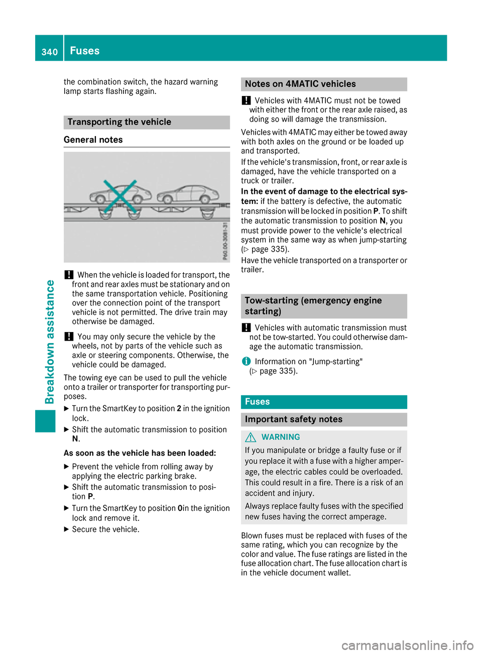
!When the vehicle is loaded for transport, the
front and rear axles must be stationary and on
the same transportation vehicle. Positioning
over the connection point of the transport
vehicle is not permitted. The drive train may
otherwise be damaged.
!You may only secure the vehicle by the
wheels, not by parts of the vehicle such as
axle or steering components. Otherwise, the
vehicle could be damaged.
The towing eye can be used to pull the vehicle
onto a trailer or transporter for transporting pur-
poses.
XTurn the SmartKey to position 2in the ignition
lock.
XShift the automatic transmission to position
N.
As soon as the vehicle has been loaded:
XPrevent the vehicle from rolling away by
applying the electric parking brake.
XShift the automatic transmission to posi-
tion P.
XTurn the SmartKey to position 0in the ignition
lock and remove it.
XSecure the vehicle.
Notes on 4MATIC vehicles
!
Vehicles with 4MATIC must not be towed
with either the front or the rear axle raised, as
doing so will damage the transmission.
Vehicles with 4MATIC may either be towed away with both axles on the ground or be loaded up
and transported.
If the vehicle's transmission, front, or rear axle is
damaged, have the vehicle transported on a
truck or trailer.
In the event of damage to the electrical sys-
tem: if the battery is defective, the automatic
transmission will be locked in position P. To shift
the automatic transmission to position N, you
must provide power to the vehicle's electrical
system in the same way as when jump-starting
(
Ypage 335).
Have the vehicle transported on a transporter or
trailer.
Tow-starting (emergency engine
starting)
!
Vehicles with automatic transmission must
not be tow-started. You could otherwise dam-
age the automatic transmission.
iInformation on "Jump-starting"
(Ypage 335).
Fuses
Important safety notes
GWARNING
If you manipulate or bridge a faulty fuse or if
you replace it with a fuse with a higher amper- age, the electric cables could be overloaded.
This could result in a fire. There is a risk of an
accident and injury.
Always replace faulty fuses with the specified
new fuses having the correct amperage.
Blown fuses must be replaced with fuses of the
same rating, which you can recognize by the
color and value. The fuse ratings are listed in the
fuse allocation chart. The fuse allocation chart is
in the vehicle document wallet.
340Fuses
Breakdown assistance
Page 365 of 382

Always observe the instructions and safety
notes in the "Mounting a wheel" section
(
Ypage 363).
The wear patterns on the front and rear tires
differ, depending on the operating conditions.
Rotate the wheels before a clear wear pattern
has formed on the tires. Front tires typically
wear more on the shoulders and the rear tires in the center.
On vehicles that have the same size front and
rear wheels, you can rotate the wheels accord-
ing to the intervals in the tire manufacturer's
warranty book in your vehicle documents. If no
warranty book is available, the tires should be
rotate every 3,000 to 6,000 miles(5,00 0 to
10,000 km). Earlier may be necessary, depend-
ing on the degree of tire wear. Do not change the
direction of wheel rotation.
Clean the contact surfaces of the wheel and the
brake disc thoroughly every time a wheel is rota- ted. Check the tire pressure and, if necessary,
restart the tire pressure loss warning system
(
Ypage 352) or the tire pressure monitor
(Ypage 351).
Direction of rotation
Tires with a specified direction of rotation have
additional benefits, e.g. if there is a risk of hydro-
planing. These advantages can only be gained if
the tires are installed corresponding to the
direction of rotation.
An arrow on the sidewall of the tire indicates its
correct direction of rotation.
Storing wheels
Store wheels that are not being used in a cool,
dry and preferably dark place. Protect the tires
from oil, grease, gasoline and diesel.
Mounting a wheel
Preparing the vehicle
XStop the vehicle on solid, non-slippery and
level ground.
XApply the electric parking brake manually.
XBring the front wheels into the straight-ahead
position.
XShift the transmission to position P.
XMake sure that the vehicle level is set to "Nor-
mal" for AIRMATIC (Ypage 182) or Active
Body Control (ABC) (Ypage 180).
XSwitch off the engine.
XOpen the driver's door.
The vehicle electronics now have status 0.
This is the same as the SmartKey having been
removed.
XRemove Start/Stop button from ignition lock
(Ypage 145).
or, if the SmartKey is inserted in the ignition
lock:
XRemove the SmartKey from the ignition lock.
XMake sure that the engine cannot be started
via your smartphone (Ypage 147).
XIf included in the vehicle equipment, remove
the tire-change tool kit from the vehicle.
XSafeguard the vehicle against rolling away.
Securing the vehicle to prevent it from
rolling away
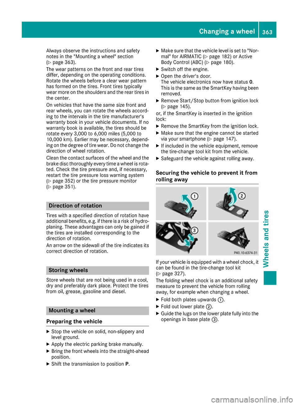
If your vehicle is equipped with a wheel chock, it can be found in the tire-change tool kit
(
Ypage 327).
The folding wheel chock is an additional safety
measure to prevent the vehicle from rolling
away, for example when changing a wheel.
XFold both plates upwards :.
XFold out lower plate;.
XGuide the lugs on the lower plate fully into the
openings in base plate =.
Changing awheel363
Wheels an d tires
Z
Page 371 of 382

Information regarding technical data
Hybrid vehicles:makesur ethat you read th e
separat eoperating instructions. Otherwise, you
may no trecognize dangers.
iThe dat astate dher especifically refers to a
vehicl ewit hstandard equipment. Consult an
authorize dMercedes-Ben zCente rfor th e
dat afor all vehicl evariants and trim levels.
Vehicle electronics
Installing two-way radios and mobile
phones (RF transmitters)
GWARNIN G
The electromagneti cradiation from modifie d
or incorrectl yretrofitte dRF-transmitters can
interfere wit hth evehicl eelectronics .This can
compromise th eoperational safet yof th e
vehicle. Ther eis aris kof an accident.
You should hav eall wor kto electrical and
electronic equipmen tcarried out at aqualified
specialist workshop.
GWARNIN G
The electromagneti cradiation from incor-
rectl yoperate dRF transmitters can interfere
wit hth evehicl eelectronics ,for example:
Rif th eRF transmitte ris no tconnecte dwit h
an exterio rantenna
Rth eexterio rantenna has been installed
incorrectl yor is no t alow-reflection typ e
This can compromise th eoperational safet y
of th evehicle. Ther eis aris kof an accident.
Hav eth elow-reflection exterio rantenna
mounte dat aqualified specialist workshop.
When operating RF transmitters in th evehi-
cle ,always connec tthem wit hth elow-reflec -
tion exterio rantenna.
!The operating permit may be invalidated if
th einstruction sfor installation and use of RF
transmitters are no tobserved. In particular, th
efollowin gcondition smust be
complied with:
Ronly approve dwavebands may be used.
Robserv eth emaximum permissible output
in these wavebands.
Ronly approve dantenna position smay be
used.
Excessiv elevels of electromagneti cradiation
may caus edamag eto your healt hand th ehealt h
of others. Using an exterio rantenna takes int o
accoun tcurren tscientific discussion srelating
to th epossible healt hhazards that may result
from electro
magneti
cfields.
Approved antenna position s(example:
Mercedes‑ Maybach)
:
Fron troo farea
;Rear roo farea
=Rear fender
?Trun klid
On vehicles wit hpanoram aroo fwit hpower tilt /
sliding panel, installin gan antenna to th efron t
or rear roo farea is no tpermitted.
On th erear fenders, it is recommended to posi-
tion th eantenna on th eside of th evehicl eclos-
est to th ecenter of th eroad .
Use th eTechnical Specification ISO/TS 2160 9
when retrofitting RF transmitters (Road Vehicles
- EM Cguidelines for installation of aftermarket
radi ofrequency transmitting equipment) .
Observ eth elegal requirements for accessory
parts.
If your vehicl ehas installation sfor two-way radi o
equipment, use th epower suppl yor antenna
connection sintended for use wit hth ebasic wir-
ing .Be sur eto observ eth emanufacturer' sSup -
plemen twhen installing.
Deviation swit hrespec tto frequency bands,
maximum transmission output sor antenna
position smust be approve dby Mercedes-Benz.
Vehicle electronics369
Technical data
Z
Page 372 of 382

The maximum transmission output (PEAK) at the
base of the antenna must not exceed the fol-
lowing values:
Frequency bandMaximum
transmission output
Short wave
3 - 54 MHz100 W
4 m waveband
74 - 78 MHz30 W
2 m waveband
144 - 174 MHz50 W
Trunked radio system/
Tetra
380 - 460 MHz10 W
70 cm waveband
400 - 460 MHz35 W
Mobile communications
(2G/3G/4G)10 W
The following can be used in the vehicle without
restrictions:
RRF transmitters with a maximum transmis-
sion output of up to 100 mW
RRF transmitters with transmitter frequencies
in the 380 - 410 MHz frequency band and a
maximum transmission output of up to 2 W
(trunked radio system/Tetra)
RMobile phones (2G/3G/4G)
There are no restrictions when positioning the
antenna on the outside of the vehicle for the
following wavebands:
RTrunked radio system/Tetra
R70 cm waveband
R2G/3G/4G
Identification plates
Vehicle identification plate with vehi-
cle identification number (VIN)
Location of vehicle identification plate (exam-
ple, left-hand-drive vehicle)
XOpen the front left-hand door.
You will see vehicle identification plate :.
Example: vehicle identification plate (USA only)
:
VIN
;Vehicle model
Example: vehicle identification plate (Canada only)
:
VIN
;Paint code
370Identification plates
Technical data
Page 373 of 382

iThe data shown on the vehicle identification
plate is used only as an example. This data is
different for every vehicle and can deviate
from the data shown here. You can find the
data applicable to your vehicle on the vehicle
identification plate.
Vehicle identification number (VIN)
XOpen the front right-hand door.
XFold cover :down and remove it.
You will see the VIN.
The VIN can also be found in the following loca-
tions:
Ron the lower edge of the windshield
(Ypage 371)
Ron the vehicle identification plate
(Ypage 370)
Engine number
:Engine number (stamped into the crank-
case)
;VIN (on the lower edge of the windshield)
=Emission control information plate, includ-
ing the certification of both federal and Cali-
fornian emissions standards
Service products and filling capaci-
ties
Important safety notes
GWARNING
Service products may be poisonous and haz-
ardous to health. There is a risk of injury.
Comply with instructions on the use, storage
and disposal of service products on the labels
of the respective original containers. Always
store service products sealed in their original
containers. Always keep service products out
of the reach of children.
HEnvironmental note
Dispose of service products in an environ-
mentally responsible manner.
Service products include the following:
RFuels
RLubricants (e.g. engine oil, transmission oil)
RCoolant
RBrake fluid
RWindshield washer fluid
RClimate control system refrigerant
Components and service products must match.
You should therefore only use products that
have been tested and approved by Mercedes-
Benz.
Information on tested and approved products
can be obtained at an authorized Mercedes-
Benz Center or on the Internet at
http://bevo.mercedes-benz.com.
You can identify service products approved by
Mercedes-Benz by the following inscriptions on
the container:
RMB-Freigabe (e.g. MB-Freigabe 229.51)
RMB-Approval (e.g. MB-Approval 229.51)
Other designations or recommendations indi-
cate a level of quality or a specification in
accordance with an MB Sheet Number (e.g. MB 229.5). They have not necessarily been
approved by Mercedes-Benz.
Other identifications, for example:
R0 W-30
R5 W-30
R5 W-40
Service products and filling capacities371
Technical data
Z