2017 MERCEDES-BENZ S-Class MAYBACH warning lights
[x] Cancel search: warning lightsPage 266 of 382

Engine
Warning/
indicator
lampNSignal type
Possible causes/consequences and M
Solutions
;NThe yellow Check Engine warning lamp lights up while the engine is running.
There may be a malfunction, for example:
Rin the engine management
Rin the fuel injection system
Rin the exhaust system
Rin the ignition system
Rin the fuel system
The emission limit values may be exceeded and the engine may be in emergency
mode.
XVisit a qualified specialist workshop immediately.
iIn some states, you must immediately visit a qualified specialist workshop as
soon as the yellow Check Engine warning lamp lights up. This is due to the legal
requirements in effect in these states. If in doubt, check whether such legal
regulations apply in the state in which you are currently driving.
8N The yellow reserve fuel warning lamp lights up while the engine is running.
The fuel level has dropped into the reserve range.
XRefuel at the nearest gas station.
8N The yellow reserve fuel warning lamp flashes while the vehicle is in motion.
In addition, the ;Check Engine warning lamp may light up.
The fuel filler cap is not closed correctly or the fuel system is leaking.
XCheck that the fuel filler cap is correctly closed.
XIf the fuel filler cap is not correctly closed: close the fuel filler cap.
XIf the fuel filler cap is closed:visit a qualified specialist workshop.
?NThe red coolant warning lamp comes on while the engine is running. The coolant
temperature gauge is at the beginning of the cold range.
The temperature sensor for the coolant temperature gauge is malfunctioning.
The coolant temperature is no longer being monitored. There is a risk of engine
damage if the coolant temperature is too high.
XPull over and stop the vehicle safely and switch off the engine, paying attention
to road and traffic conditions. Do not continue driving under any circumstances.
XSecure the vehicle against rolling away (Ypage 162).
XConsult a qualified specialist workshop.
264Warning and indicator lamps in the instrument cluster
On-board computer and displays
Page 268 of 382
Warning/
indicator
lampNSignal type
Possible causes/consequences and M
Solutions
XAt coolant temperatures below 257‡(125 †), you can continue driving to the
nearest qualified specialist workshop.
XAvoid heavy loads on the engine as you do so, e.g. driving in mountainous terrain
and stop-and-go traffic.
Driving systems
Warning/
indicator
lampNSignal type
Possible causes/consequences and M
Solutions
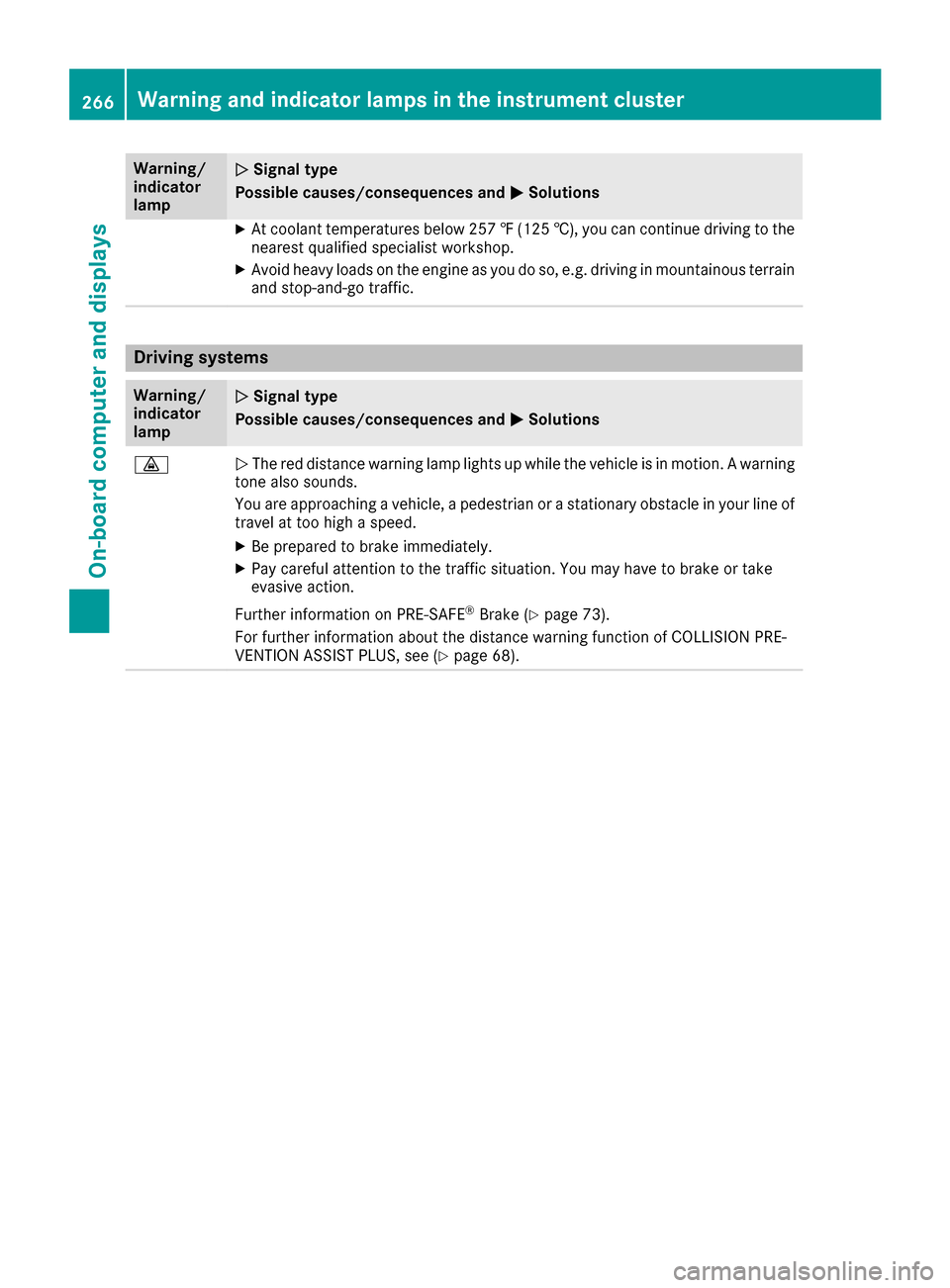
·NThe red distance warning lamp lights up while the vehicle is in motion. A warning
tone also sounds.
You are approaching a vehicle, a pedestrian or a stationary obstacle in your line of travel at too high a speed.
XBe prepared to brake immediately.
XPay careful attention to the traffic situation. You may have to brake or take
evasive action.
Further information on PRE ‑SAFE
®Brake (Ypage 73).
For further information about the distance warning function of COLLISION PRE-
VENTION ASSIST PLUS, see (
Ypage 68).
266Warning and indicator lamps in the instrument cluster
On-board computer and displays
Page 271 of 382
General notes
The multimedia system section in this Opera-
tor's Manual describes the basic principles for
operation. More information can be found in theDigital Operator's Manual.
Important safety notes
GWARNING
If you operate information systems and com-
munication equipment integrated in the vehi-
cle while driving, you will be distracted from
traffic conditions. You could also lose control
of the vehicle. There is a risk of an accident.
Only operate the equipment when the traffic
situation permits. If you are not sure that this
is possible, park the vehicle paying attention
to traffic conditions and operate the equip-
ment when the vehicle is stationary.
You must observe the legal requirements for the
country in which you are currently driving when
operating the multimedia system.
The multimedia system calculates the route to
the destination without taking the following into
account, for example:
Rtraffic lights
Rstop and yield signs
Rparking or stopping restrictions
Rroad narrowing
Rother road and traffic rules and regulations
The multimedia system may give incorrect nav-
igation recommendations if the actual street/
traffic situation does not correspond with the
digital map's data.
For example:
Ra diverted route
Rthe road layout or the direction of a one-way
street has been changed
For this reason, you must always observe road
and traffic rules and regulations during your
journey. Road and traffic rules and regulations
always have priority over multimedia system
driving recommendations.
Navigation announcements are intended to
direct you while driving without diverting your
attention from the road and driving. Please always use this feature instead of con-
sulting the map display for directions. Looking
at the icons or map display can distract you from
traffic conditions and driving, and increase the
risk of an accident.
This equipment complies with FCC radiation
exposure limits set forth for uncontrolled equip-
ment and meets the FCC radio frequency (RF)
Exposure Guidelines in Supplement C to OET65.
This equipment has very low levels of RF energy
that is deemed to comply without maximum
permissive exposure evaluation (MPE). How-
ever, it is recommended
to insta
ll it at a distance
of at least 8 inches (approx. 20 cm) between the
radiation source and a person's body (not
including limbs such as hands, wrists, feet and
legs).
GWARNING
Modifications to electronic components, their software as well as wiring can impair their
function and/or the function of other net-
worked components. In particular, systems
relevant to safety could also be affected. As a
result, these may no longer function as inten-
ded and/or jeopardize the operating safety of
the vehicle. There is an increased risk of an
accident and injury.
Never tamper with the wiring as well as elec-
tronic components or their software. You
should have all work to electrical and elec-
tronic equipment carried out at a qualified
specialist workshop.
If you make any changes to the vehicle elec-
tronics, the general operating permit is ren-
dered invalid.
Function restrictions
For safety reasons, some functions are restric-
ted or unavailable while the vehicle is in motion.
You will notice this, for example, because either
you will not be able to select certain menu items
or a message will appear to this effect.
Function restrictions269
Multimedia system
Z
Page 294 of 382
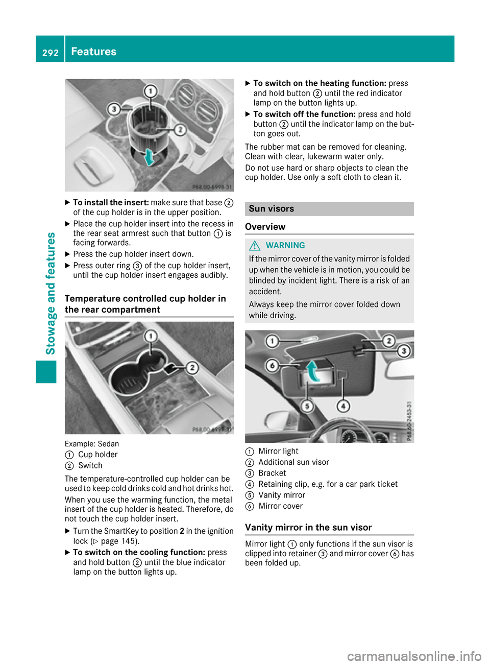
XTo install the insert:make sure that base;
of the cup holder is in the upper position.
XPlace the cup holder insert into the recess in
the rear seat armrest such that button :is
facing forwards.
XPress the cup holder insert down.
XPress outer ring =of the cup holder insert,
until the cup holder insert engages audibly.
Temperature controlled cup holder in
the rear compartment
Example: Sedan
:
Cup holder
;Switch
The temperature-controlled cup holder can be
used to keep cold drinks cold and hot drinks hot.
When you use the warming function, the metal
insert of the cup holder is heated. Therefore, do not touch the cup holder insert.
XTurn the SmartKey to position 2in the ignition
lock (Ypage 145).
XTo switch on the cooling function: press
and hold button ;until the blue indicator
lamp on the button lights up.
XTo switch on the heating function: press
and hold button ;until the red indicator
lamp on the button lights up.
XTo switch off the function: press and hold
button ;until the indicator lamp on the but-
ton goes out.
The rubber mat can be removed for cleaning.
Clean with clear, lukewarm water only.
Do not use hard or sharp objects to clean the
cup holder. Use only a soft cloth to clean it.
Sun visors
Overview
GWARNING
If the mirror cover of the vanity mirror is folded
up when the vehicle is in motion, you could be
blinded by incident light. There is a risk of an
accident.
Always keep the mirror cover folded down
while driving.
:Mirror light
;Additional sun visor
=Bracket
?Retaining clip, e.g. for a car park ticket
AVanity mirror
BMirror cover
Vanity mirror in the sun visor
Mirror light :only functions if the sun visor is
clipped into retainer =and mirror cover Bhas
been folded up.
292Features
Stowag ean d features
Page 310 of 382
door opener, contact an authorized Mercedes-
Benz Center.
Alternatively, you can call the following tele-
phone assistance services:
RUSA:Mercedes-Benz Customer Assistance
Center at 1-800-FOR-MERCedes
RCanada: Customer Service at
1-800-387-0100
RHomeLink®hotline 1-800-355-3515 (free of
charge)
More information on HomeLink
®and/or com-
patible products is also available online at
http://www.homelink.co m.
Notes on the declaration of conformity
(
Ypage 29).
USA: FCC ID: CB2HMIHL4
Canada: IC: 279B-HMIHL4
Important safety notes
GWARNING
When you operate or program the garage door
with the integrated garage door opener, per-
sons in the range of movement of the garage
door can become trapped or struck by the
garage door. There is a risk of injury.
When using the integrated garage door
opener, always make sure that nobody is
within the range of movement of the garage
door.
GWARNING
Combustion engines emit poisonous exhaust
gases such as carbon monoxide. Inhaling
these exhaust gases leads to poisoning. There
is a risk of fatal injury. Therefore never leave
the engine running in enclosed spaces with-
out sufficient ventilation.
Programming
Programming buttons
Pay attention to the "Important safety notes"
(Ypage 308).
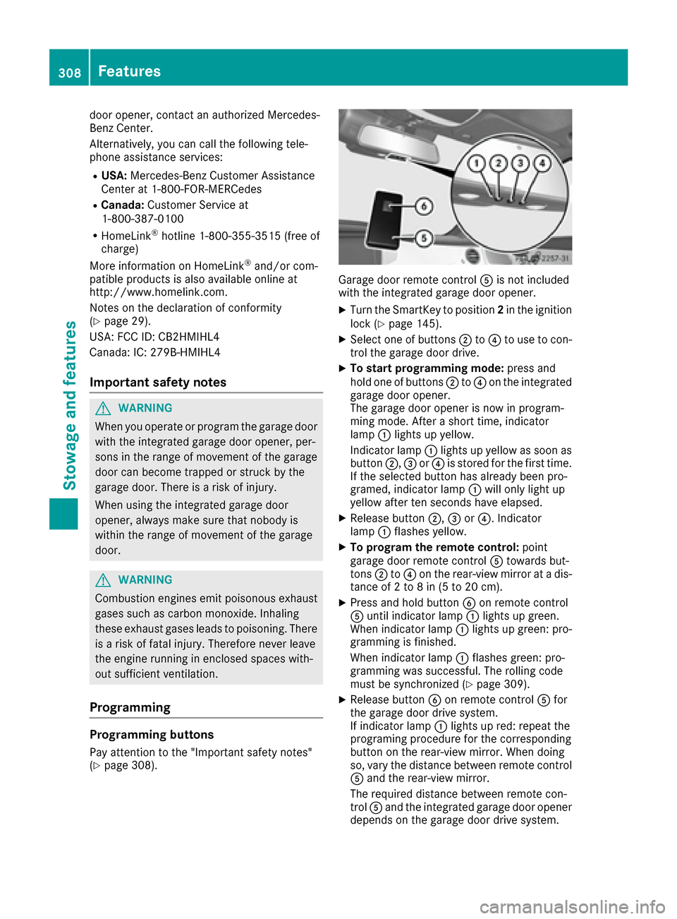
Garage door remote control Ais not included
with the integrated garage door opener.
XTurn the SmartKey to position 2in the ignition
lock (Ypage 145).
XSelect one of buttons ;to? to use to con-
trol the garage door drive.
XTo start programming mode: press and
hold one of buttons ;to? on the integrated
garage door opener.
The garage door opener is now in program-
ming mode. After a short time, indicator
lamp :lights up yellow.
Indicator lamp :lights up yellow as soon as
button ;,=or? is stored for the first time.
If the selected button has already been pro-
gramed, indicator lamp :will only light up
yellow after ten seconds have elapsed.
XRelease button ;,=or?. Indicator
lamp :flashes yellow.
XTo program the remote control: point
garage door remote control Atowards but-
tons ;to? on the rear-view mirror at a dis-
tance of 2 to 8 in (5 to 20 cm).
XPress and hold button Bon remote control
A until indicator lamp :lights up green.
When indicator lamp :lights up green: pro-
gramming is finished.
When indicator lamp :flashes green: pro-
gramming was successful. The rolling code
must be synchronized (
Ypage 309).
XRelease button Bon remote control Afor
the garage door drive system.
If indicator lamp :lights up red: repeat the
programing procedure for the corresponding
button on the rear-view mirror. When doing
so, vary the distance between remote control
A and the rear-view mirror.
The required distance between remote con-
trol Aand the integrated garage door opener
depends on the garage door drive system.
308Features
Stowage and features
Page 312 of 382
The garage door opener is compatible with
devices which operate in the frequency range
of 280 to 433 MHz.
RReplace the batteries in garage door remote
controlA. This increases the likelihood that
garage door remote control Awill transmit a
strong and precise signal to the integrated
garage door opener.
RWhen programming, hold remote control A
at varying distances and angles from but-
tons ;to? which you are programming. Try
various angles at a distance between 2and
8 inches (5to 20 cm) or at the same angle but
at varying distances.
RIf another remote control Ais available for
the same garage door drive, repeat the same
programming steps with this remote control
A. Before performing these steps, make sure
that new batteries have been installed in
garage door drive remote control A.
RNote that some remote controls only transmit
for a limited amount of time (the indicator
lamp on the remote control goes out). Press
buttonBon remote control Aagain before
transmission ends.
RAlign the antenna cable of the garage door
opener unit. This can improve signal recep-
tion/transmission.
Opening/closing the garage door
After it has been programmed, the integrated
garage door opener performs the function of the
garage door system remote control. Please also
read the operating instructions for the garage
door system.
XTurn the SmartKey to position 2in the ignition
lock (Ypage 145).
XPress button ;,=or? which you have
programmed to operate the garage door.
Garage door system with a fixed code: indi-
cator lamp :lights up green.
Garage door system with a rolling code: indi-
cator lamp :flashes green.
The transmitter will transmit a signal as long
as the button is pressed. The transmission is
halted after a maximum of ten seconds and
indicator lamp :lights up yellow.
XPress button ;,=or? again if necessary.
Clearing the memory
Make sure that you clear the memory of the
integrated garage door opener before selling the
vehicle.
XTurn the SmartKey to position 2in the ignition
lock (Ypage 145).
XPress and hold buttons ;and ?.
The indicator lamp initially lights up yellow
and then green.
XRelease buttons ;and ?.
The memory of the integrated garage door
opener in the rear-view mirror is cleared.
Floormats
GWARNING
Objects in the driver's footwell can restrict the pedal travel or obstruct a depressed pedal.
The operating and road safety of the vehicle is
jeopardized. There is a risk of an accident.
Make sure that all objects in the vehicle are
stowed correctly, and that they cannot enter
the driver's footwell. Install the floormats
securely and as specified in order to ensure
sufficient clearance for the pedals. Do not use
loose floormats and do not place floormats on
top of one another.
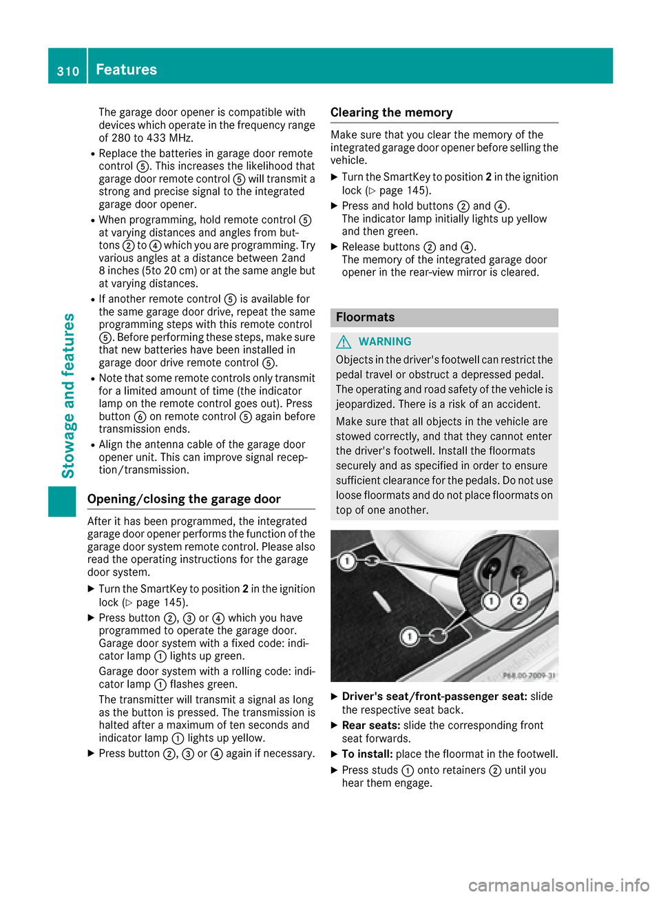
XDriver's seat/front-passenger seat: slide
the respective seat back.
XRear seats: slide the corresponding front
seat forwards.
XTo install: place the floormat in the footwell.
XPress studs :onto retainers ;until you
hear them engage.
310Features
Stowage and features
Page 324 of 382
Cleaning the vehicle parts
Cleaning the wheels
GWARNING
The water jet from a circular jet nozzle (dirt
blasters) can cause invisible exterior damage
to the tires or chassis components. Compo-
nents damaged in this way may fail unexpect-
edly. There is a risk of an accident.
Do not use power washers with circular jet
nozzles to clean the vehicle. Have damaged
tires or chassis components replaced imme-
diately.
!Do not use acidic wheel cleaning products
to remove brake dust. This could damage
wheel bolts and brake components.
!Do not park your vehicle for a long period of
time directly after cleaning, particularly after
cleaning the wheel rim with wheel cleaner.
Wheel cleaner can lead to the increased cor-
rosion of the brake discs and pads. Therefore,
drive for a few minutes after cleaning. By
heating up the brakes, the brake discs and
pads dry. The vehicle can then be parked for a
long period of time.
Cleaning the windows
GWARNING
You could become trapped by the windshield wipers if they start moving while cleaning the
windshield or wiper blades. There is a risk of
injury.
Always switch off the windshield wipers and
the ignition before cleaning the windshield or
wiper blades.
!Do not use dry cloths, abrasive products,
solvents or cleaning agents containing sol-
vents to clean the inside of the windows. Do
not touch the insides of the windows with
hard objects, e.g. an ice scraper or ring. There
is otherwise a risk of damaging the windows.
!Clean the water drainage channels of the
windshield and the rear window at regular
intervals. Deposits such as leaves, petals and pollen may under certain circumstances pre-
vent water from draining away. This can lead to corrosion damage and damage to elec-
tronic components.
XClean the inside and outside of the windows
with a damp cloth and a cleaning product that
is recommended and approved by Mercedes-
Benz.
Cleaning wiper blades
GWARNING
You could become trapped by the windshield wipers if they start moving while cleaning the
windshield or wiper blades. There is a risk of
injury.
Always switch off the windshield wipers and
the ignition before cleaning the windshield or
wiper blades.
!Do not pull the wiper blade. Otherwise, the
wiper blade could be damaged.
!Do not clean wiper blades too often and do
not rub them too hard. Otherwise, the graph-
ite coating could be damaged. This could
cause wiper noise.
!Hold the wiper arm securely when folding
back. The windshield could be damaged if the
wiper arm smacks against it suddenly.
XFold the windshield wiper arms away from the
windshield (Ypage 129).
XCarefully clean the wiper blades with a damp
cloth.
XFold the windshield wiper arms back again
before switching on the ignition.
Cleaning the exterior lighting
!Only use cleaning agents or cleaning cloths
which are suitable for plastic light lenses.
Unsuitable cleaning agents or cleaning cloths
could scratch or damage the plastic light len- ses.
XClean the plastic lenses of the exterior lights
with a wet sponge and a mild cleaning agent,
e.g. Mercedes-Benz car shampoo or cleaning
cloths.
322Care
Maintenance and care
Page 351 of 382

Checking the tire pressures
Important safety notes
Observe the notes on tire pressure
(Ypage 346).
Information on air pressure for the tires on your
vehicle can be found:
Ron the vehicle's Tire and Loading Information
placard on the B-pillar (Ypage 353)
Rin the tire pressure table in the fuel filler flap
(Ypage 162)
Rin the "Tire pressure" section
Checking tire pressures manually
To determine and set the correct tire pressure,
proceed as follows:
XRemove the valve cap of the tire that is to be
checked.
XPress the tire pressure gage securely onto the
valve.
XRead the tire pressure and compare it to the
recommended value on the Tire and Loading
Information placard or the tire pressure table (
Ypage 346).
XIf the tire pressure is too low, increase the tire
pressure to the recommended value.
XIf the tire pressure is too high, release air. To
do so, press down the metal pin in the valve,
using the tip of a pen for example. Then check
the tire pressure again using the tire pressure
checker.
XScrew the valve cap onto the valve.
XRepeat these steps for the other tires.
Tire pressure monitor
General notes
If a tire pressure monitor is installed, the vehi-
cle's wheels have sensors that monitor the tire
pressures in all four tires. The tire pressure mon-
itor warns you if the pressure drops in one or
more of the tires. The tire pressure monitor only
functions if the corresponding sensors are
installed in all wheels.
Information on tire pressures is displayed in the
multifunction display. After a few minutes of
driving, the current tire pressure of each tire is shown in the
Service
menu of the multifunction
display; see illustration (example).
For information on the message display, refer to
the "Checking the tire pressure electronically"
section (
Ypage 350).
Important safety notes
GWARNING
Each tire, including the spare (if provided),
should be checked at least once every two
weeks when cold and inflated to the pressure recommended by the vehicle manufacturer
on the Tire and Loading Information placard
on the driver's door B-pillar or the tire pres-
sure label on the inside of the fuel filler flap. If
your vehicle has tires of a different size than
the size indicated on the Tire and Loading
Information placard or, if available, the tire
pressure label, you should determine the
proper tire pressure for those tires.
As an added safety feature, your vehicle has
been equipped with a tire pressure monitoring
system (TPMS) that illuminates a low tire pres-
sure telltale when one or more of your tires
are significantly underinflated. Accordingly,
when the low tire pressure telltale lights up,
you should stop and check your tires as soon
as possible, and inflate them to the proper
pressure. Driving on a significantly underin-
flated tire causes the tire to overheat and can
lead to tire failure.
Underinflation also reduces fuel efficiency
and tire tread life, and may affect the vehicle's
handling and stopping ability. Please note thatthe TPMS is not a substitute for proper tire
maintenance, and it is the driver's responsi-
bility to maintain correct tire pressure, eve n if
un
derinflation has not reached the level to
Tire pressure349
Wheels and tires
Z