2017 MERCEDES-BENZ S-Class COUPE oil pressure
[x] Cancel search: oil pressurePage 22 of 338
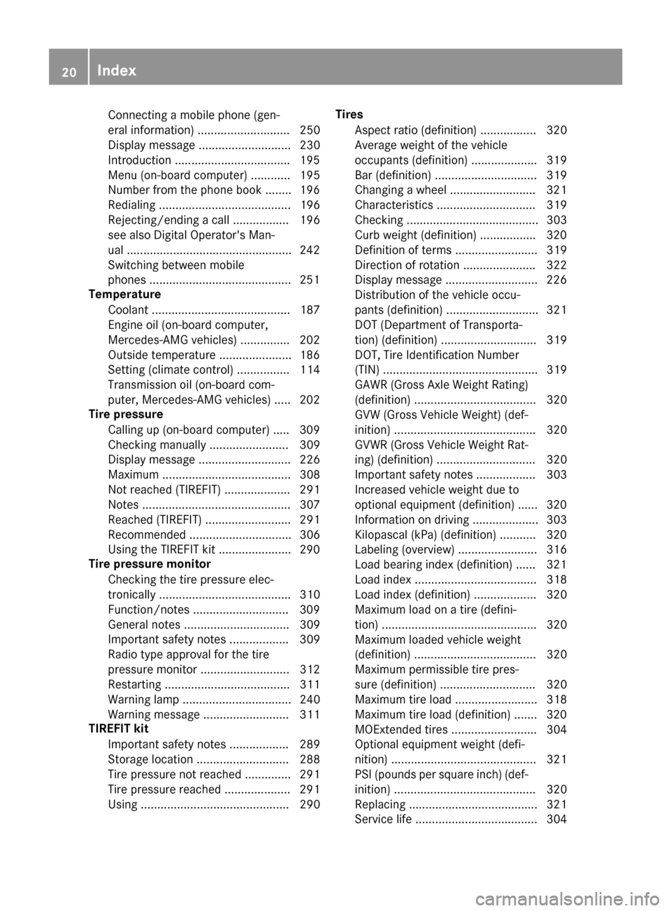
Connecting a mobile phone (gen-
eral information) ............................ 250
Display message ............................ 230
In troduction .................................. .195
Menu (on-board computer) ............ 195
Number from the phone book ........1 96
Redialing ........................................ 196
Rejecting/ending a call ................. 196
see also Digital Operator's Man-
ual ..................................................2 42
Switching between mobile
phones ...........................................2 51
Temperature
Coolant .......................................... 187
Engine oil (on-board computer,
Mercedes-AMG vehicles) ...............2 02
Outside temperature ......................1 86
Setting (climate control) ................ 114
Transmission oil (on-board com-
puter, Mercedes-AMG vehicles) ..... 202
Tire pressure
Calling up (on-board computer) ..... 309
Checking manually ........................ 309
Display message ............................ 226
Maximum ....................................... 308
Not reached (TIREFIT) .................... 291
Notes ............................................. 307
Reached (TIREFIT) .......................... 291
Recommended ............................... 306
Using the TIREFIT kit ......................2 90
Tire pressure monitor
Checking the tire pressure elec-
tronically ........................................ 310
Function/notes .............................3 09
General notes ................................ 309
Important safety notes .................. 309
Radio type approval for the tire
pressure monitor ........................... 312
Restarting ...................................... 311
Warning lamp ................................. 240
Warning message .......................... 311
TIREFIT kit
Important safety notes .................. 289
Storage location ............................ 288
Tire pressu
re not reached .............. 291
Tire pressure reached .................... 291
Using ............................................. 290 Tires
Aspect ratio (definition) ................. 320
Average weight of the vehicle
occupants (definition) .................... 319
Bar (definition) ............................... 319
Changing a wheel .......................... 321
Characteristics .............................. 319
Checking ........................................ 303
Curb weight (definition) ................. 320
Definition of terms ......................... 319
Direction of rotation ...................... 322
Display message ............................ 226
Distribution of the vehicle occu-
pants (definition) ............................ 321
DOT (Department of Transporta-
tion) (definition) ............................. 319
DOT, Tire Identification Number
(TIN) ............................................... 319
GAWR (Gross Axle Weight Rating)
(definition) ..................................... 320
GVW (Gross Vehicle Weight) (def-
inition) ........................................... 320
GVWR (Gross Vehicle Weight Rat-
ing) (definition) .............................. 320
Important safety notes .................. 303
Increased vehicle weight due to
optional equipment (definition) ...... 320
Information on driving .................... 303
Kilopascal (kPa) (definition) ........... 320
Labeling (overview) ........................ 316
Load bearing index (definition) ...... 321
Load index ..................................... 318
Load index (definition) ................... 320
Maximum load on a tire (defini-
tion) ............................................... 320
Maximum loaded vehicle weight
(definition) ..................................... 320
Maximum permissible tire pres-
sure (definition) ............................. 320
Maximum tire load ......................... 318
Maximum tire load (definition) ....... 320
MOExtended tires .......................... 304
Optional equipme nt w
eight (defi-
nition) ............................................ 321
PSI (pounds per square inch) (def-
inition) ........................................... 320
Replacing ....................................... 321
Service life ..................................... 304
20Index
Page 279 of 338
XReplacecap 0043on th efiller neck and tighten
clockwise.
Ensur ethat th ecap locks int oplac esecurely.
XChec kth eoil level again usin gth eoil dipstick
(except Mercedes-AM G S65) (Ypage 275).
XChec kth eoil level again usin gth eon-board
computer (Mercedes-AM G S65)
(
Ypage 275).
Further information on engin eoil (
Ypage 332).
Additional service products
Important safety notes
GWARNIN G
Certain component sin th eengin ecompart-
ment, suc has th eengine, radiato rand part s
of th eexhaust system, can become ver yhot .
Workin gin th eengin ecompartmen tposes a
ris kof injury.
Wher epossible, let th eengin ecool down and
touch only th ecomponent sdescribe din th e
following.
GWARNIN G
The engin ecompartmen tcontain smoving
components. Certain components, suc has
th eradiato rfan ,may continue to run or start
again suddenly when th eignition is off .There
is aris kof injury.
If you need to do any wor kinside th eengin e
compartment:
Rswitch off th eignition
Rnever reac hint oth earea wher ethere is a
ris kof danger from moving components,
suc has th efan rotation area
Rremove jewelr yand watches
Rkeep items of clothing and hair ,for exam-
ple, away from moving part s
GWARNING
The coolin gsystem is pressurized, particularly
when th emotor is warm .If you open th ecap ,
you could be scalded if hot coolan tsprays out .
There is aris kof injury.
Let th eengin ecool down before you open th e
cap .Wear gloves and eye protection .Slowly
open th ecap to reliev epressure.
GWARNIN G
Opening th ehoo dwhen th eengin eis over-
heated or when there is afir ein th eengin e
compartmen tcould expos eyou to hot gase s
or other servic eproducts .There is aris kof
injury.
Let an overheate dengin ecool down before
opening th ehood. If there is afir ein th e
engin ecompartment, keep th ehoo dclosed
and contact th efir edepartment.
Checking coolant level
GWARNIN G
Certain component sin th eengin ecompart-
ment, suc has th eengine, radiato rand part s
of th eexhaust system, can become ver yhot .
Workin gin th eengin ecompartmen tposes a
ris kof injury.
Wher epossible, let th eengin ecool down and
touch only th ecomponent sdescribe din th e
following.
GWARNIN G
The coolin gsystem is pressurized, particularly
when th emotor is warm .If you open th ecap ,
you could be scalded if hot coolan tsprays out .
There is aris kof injury.
Let th eengin ecool down before you open th e
cap .Wear gloves and eye protection .Slowly
open th ecap to reliev epressure.
Engine compartment277
Maintenance and care
Z
Page 293 of 338
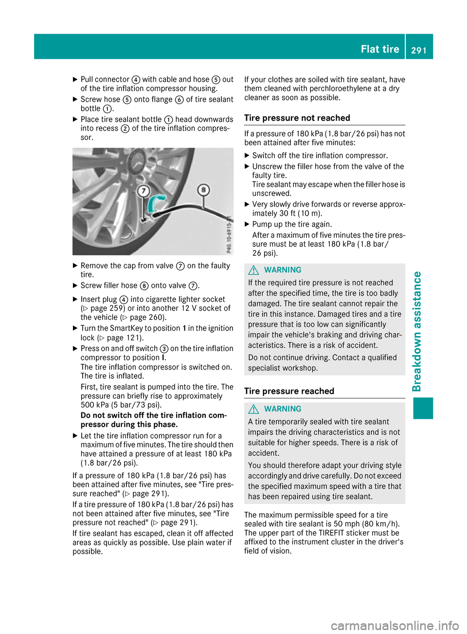
XPull connector0085with cable and hose 0083out
of the tire inflation compressor housing.
XScrew hose 0083onto flange 0084of tire sealant
bottle 0043.
XPlace tire sealant bottle 0043head downwards
into recess 0044of the tire inflation compres-
sor.
XRemove the cap from valve 006Bon the faulty
tire.
XScrew filler hose 006Conto valve 006B.
XInsert plug 0085into cigarette lighter socket
(Ypage 259) or into another 12 V socket of
the vehicle (Ypage 260).
XTurn the SmartKey to position 1in the ignition
lock (Ypage 121).
XPress on and off switch 0087on the tire inflation
compressor to position I.
The tire inflation compressor is switched on.
The tire is inflated.
First, tire sealant is pumped into the tire. The
pressure can briefly rise to approximately
500 kPa (5 bar/73 psi).
Do not switch off the tire inflation com-
pressor during this phase.
XLet the tire inflation compressor run for a
maximum of five minutes. The tire should then
have attained a pressure of at least 180 kPa
(1.8 bar/26 psi).
If a pressure of 180 kPa (1.8 bar/26 psi) has
been attained after five minutes, see "Tire pres-
sure reached" (
Ypage 291).
If a tire pressure of 180 kPa (1.8 bar/26 psi) has
not been attained after five minutes, see "Tire
pressure not reached" (
Ypage 291).
If tire sealant has escaped, clean it off affected
areas as quickly as possible. Use plain water if
possible. If your clothes are soiled with tire sealant, have
them cleaned with perchloroethylene at a dry
cleaner as soon as possible.
Tire pressure not reached
If a pressure of 180 kPa (1.8 bar/26 psi) has not
been attained after five minutes:
XSwitch off the tire inflation compressor.
XUnscrew the filler hose from the valve of the
faulty tire.
Tire sealant may escape when the filler hose is
unscrewed.
XVery slowly drive forwards or reverse approx- imately 30 ft (10 m).
XPump up the tire again.
After a maximum of five minutes the tire pres-
sure must be at least 180 kPa (1.8 bar/
26 psi).
GWARNING
If the required tire pressure is not reached
after the specified time, the tire is too badly
damaged. The tire sealant cannot repair the
tire in this instance. Damaged tires and a tire
pressure that is too low can significantly
impair the vehicle's braking and driving char-
acteristics. There is a risk of accident.
Do not continue driving. Contact a qualified
specialist workshop.
Tire pressure reached
GWARNING
A tire temporarily sealed with tire sealant
impairs the driving characteristics and is not
suitable for higher speeds. There is a risk of
accident.
You should therefore adapt your driving style
accordingly and drive carefully. Do not exceed the specified maximum speed with a tire that
has been repaired using tire sealant.
The maximum permissible speed for a tire
sealed with tire sealant is 50 mph (80 km/h).
The upper part of the TIREFIT sticker must be
affixed to the instrument cluster in the driver's
field of vision.
Flat tire291
Breakdown assistance
Z
Page 322 of 338
following specifications from the U.S. govern-
ment. The ratings are molded into the sidewall of
the tire.
Recommended tire pressures
The recommended tire pressure applies to the
tires mounted at the factory.
The Tire and Loading Information placard con-
tains the recommended tire pressures for cold
tires on a fully loaded vehicle and for the maxi-
mum permissible vehicle speed.
The tire pressure table contains the recommen-ded pressures for cold tires for various operat-
ing conditions, i.e. differing load and speed con-
ditions.
Increased vehicle weight due to optional
equipment
The combined weight of all standard and
optional equipment available for the vehicle,
regardless of whether it is actually installed on
the vehicle or not.
Rim
This is the part of the wheel on which the tire is
mounted.
GAWR (Gross Axle Weight Rating)
The GAWR is the maximum gross axle weight
rating. The actual load on an axle must never
exceed the gross axle weight rating. The gross
axle weight rating can be found on the vehicle
identification plate on the B-pillar on the driver's
side.
Speed rating
The speed rating is part of the tire identification. It specifies the speed range for which the tire is
approved.
GVW (Gross Vehicle Weight)
The gross vehicle weight includes the weight of
the vehicle including fuel, tools, the spare wheel,
accessories installed, occupants, luggage and
the drawbar noseweight, if applicable. The gross
vehicle weight must not exceed the gross vehi-
cle weight rating GVWR as specified on the vehi-
cle identification plate on the B-pillar on the
driver's side.
GVWR (Gross Vehicle Weight Rating)
The GVWR is the maximum permissible gross
weight of a fully loaded vehicle (the weight of the
vehicle including all accessories, occupants, fuel, luggage and the drawbar noseweight, if
applicable). The gross vehicle weight rating is
specified on the vehicle identification plate on
the B-pillar on the driver's side.
Maximum loaded vehicle weight
The maximum weight is the sum of:
Rthe curb weight of the vehicle
Rthe weight of the accessories
Rthe load limit
Rthe weight of the factory installed optional
equipment
Kilopascal (kPa)
Metric unit for tire pressure. 6.9 kPa corre-
sponds to 1 psi. Another unit for tire pressure is
bar. 100 kilopascals (kPa) are the equivalent of
1 bar.
Load index
In addition to the load-bearing index, the load
index may also be imprinted on the sidewall of
the tire. This specifies the load-bearing capacity
more precisely.
Curb weight
The weight of a vehicle with standard equipment
including the maximum capacity of fuel, oil and
coolant. It also includes the air-conditioning sys-
tem and optional equipment if these are instal-
led in the vehicle, but does not include passen-
gers or luggage.
Maximum load rating
The maximum tire load is the maximum permis-
sible weight in kilograms or lbs for which a tire is
approved.
Maximum permissible tire pressure
Maximum permissible tire pressure for one tire.
Maximum load on one tire
Maximum load on one tire. This is calculated by
dividing the maximum axle load of one axle by
two.
PSI (pounds per square inch)
A standard unit of measure for tire pressure.
Aspect ratio
Relationship between tire height and tire width
in percent.
320All about wheels and tires
Wheels and tires
Page 324 of 338
Always observe the instructions and safety
notes in the "Mounting a wheel" section
(
Ypage 322).
The wear patterns on the front and rear tires
differ, depending on the operating conditions.
Rotate the wheels before a clear wear pattern
has formed on the tires. Front tires typically
wear more on the shoulders and the rear tires in the center.
On vehicles that have the same size front and
rear wheels, you can rotate the wheels accord-
ing to the intervals in the tire manufacturer's
warranty book in your vehicle documents. If no
warranty book is available, the tires should be
rotate every 3,000 to 6,000 miles(5,00 0 to
10,000 km). Earlier may be necessary, depend-
ing on the degree of tire wear. Do not change the
direction of wheel rotation.
Clean the contact surfaces of the wheel and the
brake disc thoroughly every time a wheel is rota- ted. Check the tire pressure and reactivate the
tire pressure monitor if necessary (
Ypage 311).
Direction of rotation
Tires with a specified direction of rotation have
additional benefits, e.g. if there is a risk of hydro-
planing. These advantages can only be gained if
the tires are installed corresponding to the
direction of rotation.
An arrow on the sidewall of the tire indicates its
correct direction of rotation.
Storing wheels
Store wheels that are not being used in a cool,
dry and preferably dark place. Protect the tires
from oil, grease, gasoline and diesel.
Mounting a wheel
Preparing the vehicle
XStop the vehicle on solid, non-slippery and
level ground.
XApply the electric parking brake manually.
XBring the front wheels into the straight-ahead position.
XShift the transmission to position P.
XMake sure that the vehicle level is set to "Nor-
mal" for AIRMATIC (Ypage 158) or Active
Body Control (ABC) (Ypage 156).
XSwitch off the engine.
XOpen the driver's door.
The vehicle electronics now have status 0.
This is the same as the SmartKey having been
removed.
XRemove Start/Stop button from ignition lock
(Ypage 121).
or, if the SmartKey is inserted in the ignition
lock:
XRemove the SmartKey from the ignition lock.
XMake sure that the engine cannot be started
via your smartphone (Ypage 123).
XIf included in the vehicle equipment, remove
the tire-change tool kit from the vehicle.
XSafeguard the vehicle against rolling away.
Securing the vehicle to prevent it from
rolling away
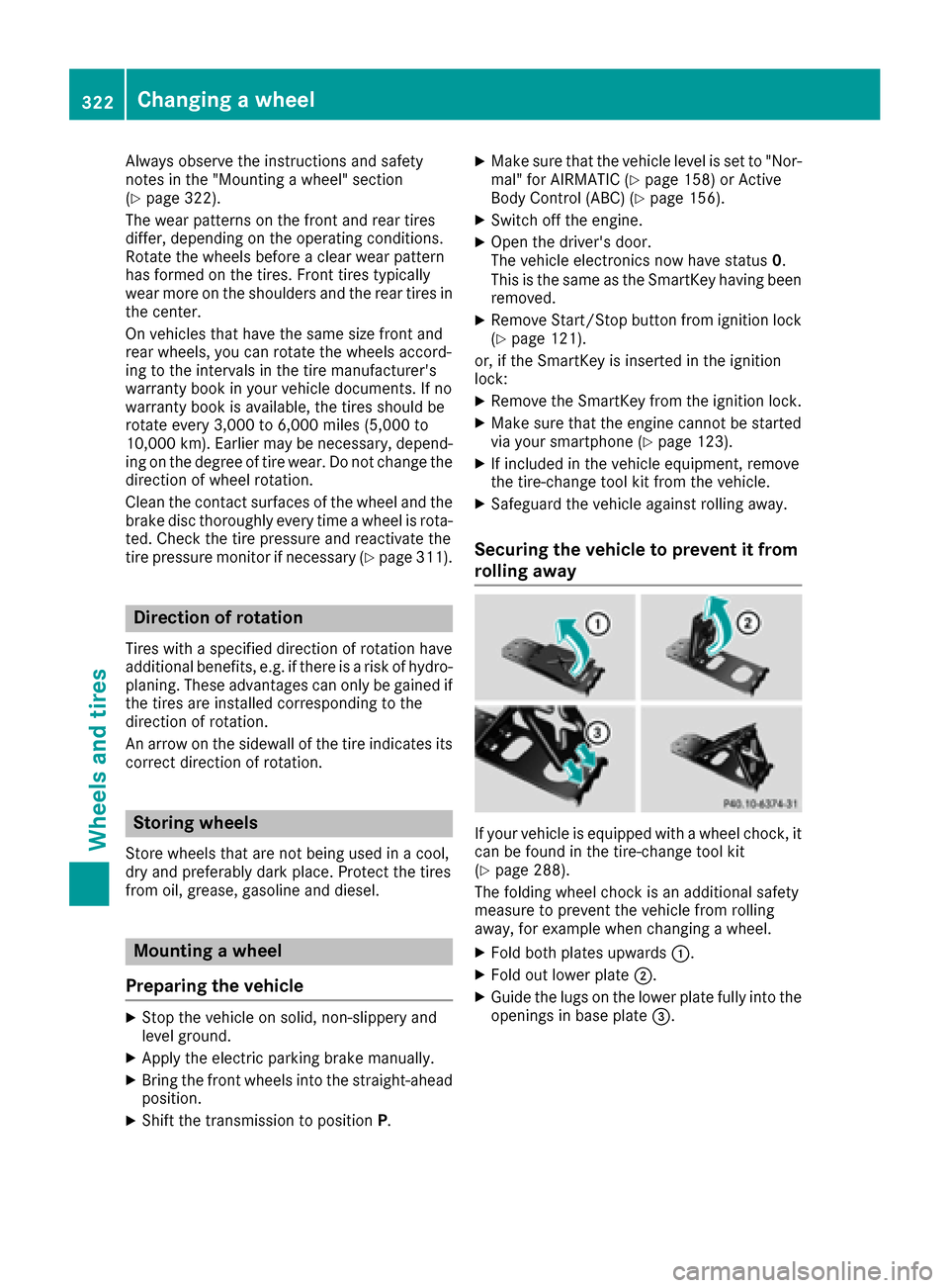
If your vehicle is equipped with a wheel chock, it can be found in the tire-change tool kit
(
Ypage 288).
The folding wheel chock is an additional safety
measure to prevent the vehicle from rolling
away, for example when changing a wheel.
XFold both plates upwards 0043.
XFold out lower plate0044.
XGuide the lugs on the lower plate fully into the
openings in base plate 0087.
322Changing awheel
Wheels an d tires