2017 MERCEDES-BENZ S-Class COUPE door lock
[x] Cancel search: door lockPage 290 of 338

Where will I find...?
Vehicle tool kit
General notes
Apart from certain country-specific variations,
the vehicles are not equipped with a tire-change
tool kit. If your vehicle is equipped with a tire-
change tool kit, it is located in the stowage well
under the trunk floor. Some tools for changing a
wheel are specific to the vehicle. For more infor-
mation on which tire changing tools are required
and approved to perform a wheel change on
your vehicle, consult a qualified specialist work- shop.
Necessary tire-changing tools can include, for
example:
RJack
RWheel chock
RLug wrench
RRatchet wrench
RAlignment bolt
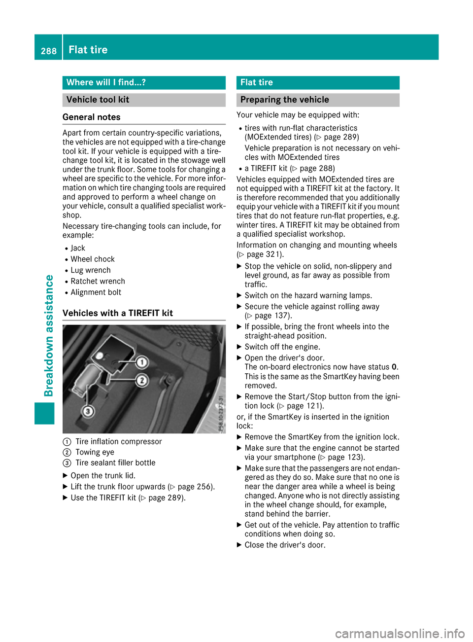
Vehicles with a TIREFIT kit
0043Tire inflation compressor
0044Towing eye
0087Tire sealant filler bottle
XOpen the trunk lid.
XLift the trunk floor upwards (Ypage 256).
XUse the TIREFIT kit (Ypage 289).
Flat tire
Preparing the vehicle
Your vehicle may be equipped with:
Rtires with run-flat characteristics
(MOExtended tires) (Ypage 289)
Vehicle preparation is not necessary on vehi-
cles with MOExtended tires
Ra TIREFIT kit (Ypage 288)
Vehicles equipped with MOExtended tires are
not equipped with a TIREFIT kit at the factory. It
is therefore recommended that you additionally
equip your vehicle with a TIREFIT kit if you mount
tires that do not feature run-flat properties, e.g.
winter tires. A TIREFIT kit may be obtained from a qualified specialist workshop.
Information on changing and mounting wheels
(
Ypage 321).
XStop the vehicle on solid, non-slippery and
level ground, as far away as possible from
traffic.
XSwitch on the hazard warning lamps.
XSecure the vehicle against rolling away
(Ypage 137).
XIf possible, bring the front wheels into the
straight-ahead position.
XSwitch off the engine.
XOpen the driver's door.
The on-board electronics now have status 0.
This is the same as the SmartKey having been
removed.
XRemove the Start/Stop button from the igni-
tion lock (Ypage 121).
or, if the SmartKey is inserted in the ignition
lock:
XRemove the SmartKey from the ignition lock.
XMake sure that the engine cannot be started
via your smartphone (Ypage 123).
XMake sure that the passengers are not endan-
gered as they do so. Make sure that no one is near the danger area while a wheel is being
changed. Anyone who is not directly assisting
in the wheel change should, for example,
stand behind the barrier.
XGet out of the vehicle. Pay attention to traffic
conditions when doing so.
XClose the driver's door.
288Flat tire
Breakdown assistance
Page 301 of 338

!When towing, pull away slowly and
smoothly. If the tractive power is too high, the
vehicles could be damaged.
!Shift the automatic transmission to Nand
do not open the driver's or front passenger's
door during towing. The automatic transmis-
sion may otherwise shift to position P, which
could damage the transmission.
!Do not tow with sling-type equipment. This
could damage the vehicle.
!The vehicle can be towed a maximum of
30 miles (50km). The towing speed of 30 mph (50 km/h) must not be exceeded.
If the vehicle has to be towed more than
30 miles (50km), the entire vehicle must be
raised and transported.
It is better to have the vehicle transported than
to have it towed away.
If the vehicle has suffered transmission damage,
have it transported on a transporter or trailer.
The automatic transmission must be in position N when the vehicle is being towed.
If the automatic transmission cannot be shifted
to position N, have the vehicle transported on a
transporter or trailer.
The battery must be connected and charged.
Otherwise, you:
Rcannot turn the SmartKey to position 2in the
ignition lock
Rcannot release the electric parking brake
Rcannot shift the automatic transmission to
position N
Disarm the automatic locking feature before the
vehicle is towed (
Ypage 79). You could other-
wise be locked out when pushing or towing the
vehicle.
Installing/removing the towing eye
Installing the towing eye
GWARNING
The exhaust tail pipe may be very hot. There is
a risk of burns when removing the rear cover.
Do not touch the exhaust pipe. Take particular
care when removing the rear cover.
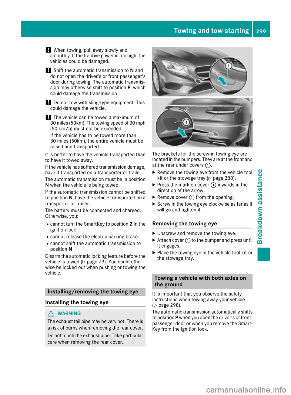
The brackets for the screw-in towing eye are
located in the bumpers. They are at the front and
at the rear under covers 0043.
XRemove the towing eye from the vehicle tool
kit or the stowage tray (Ypage 288).
XPress the mark on cover 0043inwards in the
direction of the arrow.
XRemove cover 0043from the opening.
XScrew in the towing eye clockwise as far as it
will go and tighten it.
Removing the towing eye
XUnscrew and remove the towing eye.
XAttach cover 0043to the bumper and press until
it engages.
XPlace the towing eye in the vehicle tool kit or
the stowage tray.
Towing a vehicle with both axles on
the ground
It is important that you observe the safety
instructions when towing away your vehicle
(
Ypage 298).
The automatic transmission automatically shifts
to position Pwhen you open the driver's or front-
passenger door or when you remove the Smart-
Key from the ignition lock.
Towing and tow-starting299
Breakdown assistance
Z
Page 324 of 338

Always observe the instructions and safety
notes in the "Mounting a wheel" section
(
Ypage 322).
The wear patterns on the front and rear tires
differ, depending on the operating conditions.
Rotate the wheels before a clear wear pattern
has formed on the tires. Front tires typically
wear more on the shoulders and the rear tires in the center.
On vehicles that have the same size front and
rear wheels, you can rotate the wheels accord-
ing to the intervals in the tire manufacturer's
warranty book in your vehicle documents. If no
warranty book is available, the tires should be
rotate every 3,000 to 6,000 miles(5,00 0 to
10,000 km). Earlier may be necessary, depend-
ing on the degree of tire wear. Do not change the
direction of wheel rotation.
Clean the contact surfaces of the wheel and the
brake disc thoroughly every time a wheel is rota- ted. Check the tire pressure and reactivate the
tire pressure monitor if necessary (
Ypage 311).
Direction of rotation
Tires with a specified direction of rotation have
additional benefits, e.g. if there is a risk of hydro-
planing. These advantages can only be gained if
the tires are installed corresponding to the
direction of rotation.
An arrow on the sidewall of the tire indicates its
correct direction of rotation.
Storing wheels
Store wheels that are not being used in a cool,
dry and preferably dark place. Protect the tires
from oil, grease, gasoline and diesel.
Mounting a wheel
Preparing the vehicle
XStop the vehicle on solid, non-slippery and
level ground.
XApply the electric parking brake manually.
XBring the front wheels into the straight-ahead position.
XShift the transmission to position P.
XMake sure that the vehicle level is set to "Nor-
mal" for AIRMATIC (Ypage 158) or Active
Body Control (ABC) (Ypage 156).
XSwitch off the engine.
XOpen the driver's door.
The vehicle electronics now have status 0.
This is the same as the SmartKey having been
removed.
XRemove Start/Stop button from ignition lock
(Ypage 121).
or, if the SmartKey is inserted in the ignition
lock:
XRemove the SmartKey from the ignition lock.
XMake sure that the engine cannot be started
via your smartphone (Ypage 123).
XIf included in the vehicle equipment, remove
the tire-change tool kit from the vehicle.
XSafeguard the vehicle against rolling away.
Securing the vehicle to prevent it from
rolling away
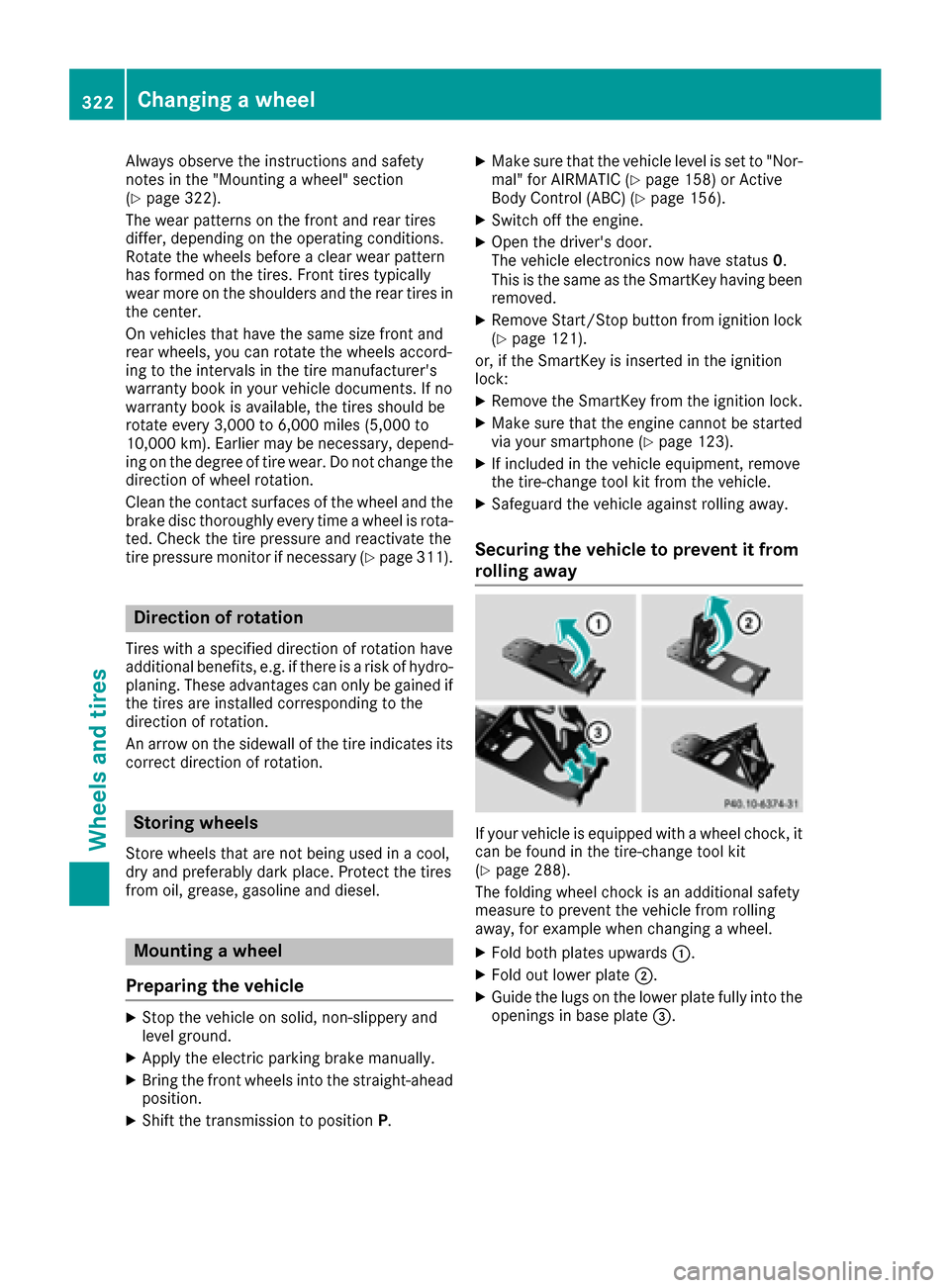
If your vehicle is equipped with a wheel chock, it can be found in the tire-change tool kit
(
Ypage 288).
The folding wheel chock is an additional safety
measure to prevent the vehicle from rolling
away, for example when changing a wheel.
XFold both plates upwards 0043.
XFold out lower plate0044.
XGuide the lugs on the lower plate fully into the
openings in base plate 0087.
322Changing awheel
Wheels an d tires
Page 325 of 338

XPlace chocks or other suitable items under
the front and rear of the wheel that is diago-
nally opposite the wheel you wish to change.
Raising the vehicle
GWARNING
If you do not position the jack correctly at the
appropriate jacking point of the vehicle, the
jack could tip over with the vehicle raised.
There is a risk of injury.
Only position the jack at the appropriate jack-
ing point of the vehicle. The base of the jack
must be positioned vertically, directly under
the jacking point of the vehicle.
!The jack is designed exclusively for jacking
up the vehicle at the jacking points. Other-
wise, your vehicle could be damaged.
Observe the following when raising the vehi-
cle:
RTo raise the vehicle, only use the vehicle-spe-
cific jack that has been tested and approved
by Mercedes-Benz. If used incorrectly, the
jack could tip over with the vehicle raised.
RThe jack is designed only to raise and hold the
vehicle for a short time while a wheel is being
changed. It must not be used for performing
maintenance work under the vehicle.
RAvoid changing the wheel on uphill and down-
hill slopes.
RBefore raising the vehicle, secure it from roll-
ing away by applying the parking brake and
inserting wheel chocks. Do not disengage the
parking brake while the vehicle is raised.
RThe jack must be placed on a firm, flat and
non-slip surface. On a loose surface, a large,
flat, load-bearing underlay must be used. On a slippery surface, a non-slip underlay must be
used, e.g. rubber mats.
RDo not use wooden blocks or similar objects
as a jack underlay. Otherwise, the jack will not
be able to achieve its load-bearing capacity
due to the restricted height.
RMake sure that the distance between the
underside of the tires and the ground does not
exceed 1.2 in (3 cm).
RDo not place your hands or feet under the
raised vehicle.
RDo not lie under the vehicle.
RDo not start the engine when the vehicle is
raised.
RDo not open or close a door or the trunk lid
when the vehicle is raised.
RMake sure that no persons are present in the
vehicle when the vehicle is raised.
Vehicles with AMG wheels and hub caps: the
hub cap covers the wheel bolts. Before you can
unscrew the wheel bolts, you must remove the
hub cap. Two different variant
s can be installed.
Vehicles with AMG wheels and plastic hub
caps:
XTo remove: turn the center cover of hub
cap 0043counter-clockwise and remove.
XTo install: before installing, ensure that hub
cap 0043is in the open position. To do this, turn
the center cover counter-clockwise.
XPosition hub cap 0043and turn the center cover
clockwise until hub cap 0043engages physically
and audibly.
XMake sure that hub cap 0043is installed
securely.
Changing a wheel323
Wheels and tires
Z