2017 MERCEDES-BENZ GLS spare wheel
[x] Cancel search: spare wheelPage 351 of 390
To avoid hazardous situations: R
never install snow chains to the front
wheels R
always install snow chains in pairs to the
rear wheels.
! You must drive at raised vehicle level (height
1) if snow chains have been installed. The
vehicle may otherwise be damaged.
! Vehicles with ADS (Adaptive Damping
System): do not use the sport mode when
driving with snow chains mounted. The vehi-
cle may otherwise be damaged.
For safety reasons, Mercedes-Benz recom-
mends that you only use snow chains that have
been specially approved for your vehicle by
Mercedes-Benz, or are of a corresponding
standard of quality. For more information,
please contact a qualified specialist workshop.
Install the snow chains on all driven wheels for
maximum tractive power and driving stability. If
you own snow chains for two driven wheels only,
install the snow chains to the wheels on the rear
axle. The vehicle then remains more stable
under braking.
If you intend to mount snow chains, please bear
the following points in mind: R
Snow chains may not be mounted on all
wheel/tire combinations. Permissible
wheel/tire combinations ( Y
page 371).R
Only use snow chains when driving on roads
completely covered by snow. Remove the
snow chains as soon as possible when you
come to a road that is not snow-covered. R
Local regulations may restrict the use of snow
chains. Observe the appropriate regulations if
you wish to mount snow chains. R
Do not exceed the maximum permissible
speed of 30 mph (50 km/h). R
Never use Parking Pilot when snow chains are
installed ( Y
page 193).
You may wish to deactivate ESP ®
when pulling
away with snow chains installed ( Y
page 67).
You can thereby allow the wheels to spin in a
controlled manner, achieving an increased driv-
ing force (cutting action).
Information about driving with an emergency
spare wheel ( Y
page 372). Tire pressure
Tire pressure specifications
Important safety notes
G WARNING
Underinflated or overinflated tires pose the
following risks: R
the tires may burst, especially as the load
and vehicle speed increase. R
the tires may wear excessively and/or
unevenly, which may greatly impair tire
traction. R
the driving characteristics, as well as steer-
ing and braking, may be greatly impaired.
There is a risk of an accident.
Follow recommended tire inflation pressures
and check the pressure of all the tires includ-
ing the spare wheel: R
monthly, at least R
if the load changes R
before beginning a long journey R
under different operating conditions, e.g.
off-road driving
If necessary, correct the tire pressure.
The data on the Tire and Loading Information
placard and tire pressure table shown here are
examples. Tire pressure specifications are vehi-
cle-specific and may deviate from the data
shown here. The tire pressure specifications
that are valid for your vehicle can be found on
the Tire and Loading Information placard and
tire pressure table on the vehicle.
General notes The recommended tire pressures for the tires
mounted at the factory can be found on the
labels described here.
Operation with emergency spare wheel:
Information on operation with the emergency
spare wheel can be found under "Emergency
spare wheel" ( Y
page 372).
Operation with a trailer: the applicable value
for the rear axle is the maximum tire pressure
value stated in the table inside the fuel filler flap. Tire pressure 349
Wheels and tires Z
Page 354 of 390
Avoid tire pressures that are too high in all the
tires, including the spare wheel.
Overinflated tires may: R
increase the braking distance R
adversely affect handling R
wear excessively and/or unevenly R
have an adverse effect on ride comfort R
be more susceptible to damage
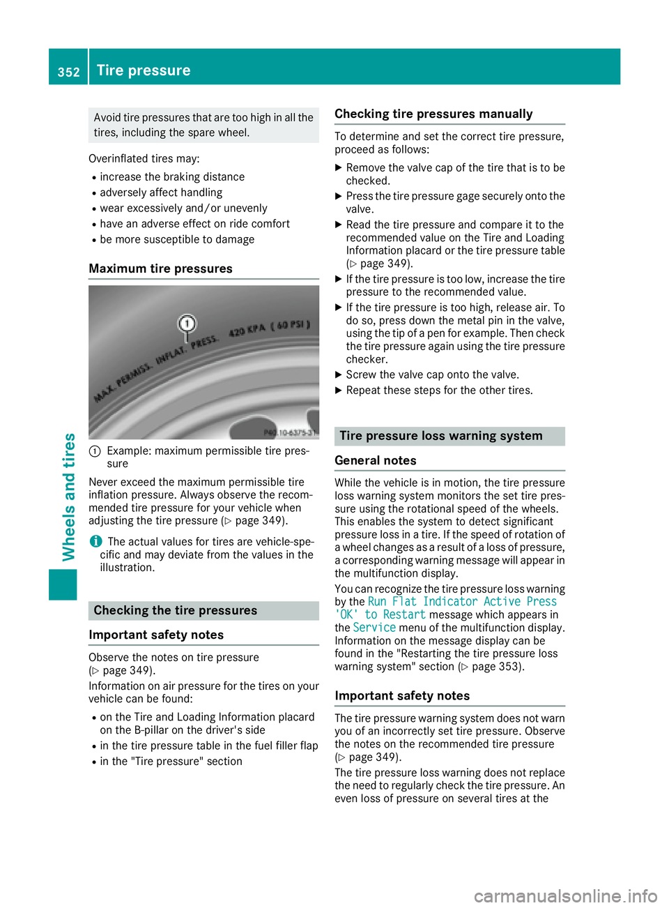
Maximum tire pressures
C
Example: maximum permissible tire pres-
sure
Never exceed the maximum permissible tire
inflation pressure. Always observe the recom-
mended tire pressure for your vehicle when
adjusting the tire pressure ( Y
page 349).
i The actual values for tires are vehicle-spe-
cific and may deviate from the values in the
illustration.
Checking the tire pressures
Important safety notes Observe the notes on tire pressure
( Y
page 349).
Information on air pressure for the tires on your
vehicle can be found: R
on the Tire and Loading Information placard
on the B-pillar on the driver's side R
in the tire pressure table in the fuel filler flap R
in the "Tire pressure" section Checking tire pressures manually To determine and set the correct tire pressure,
proceed as follows: X
Remove the valve cap of the tire that is to be
checked. X
Press the tire pressure gage securely onto the
valve. X
Read the tire pressure and compare it to the
recommended value on the Tire and Loading
Information placard or the tire pressure table
( Y
page 349). X
If the tire pressure is too low, increase the tire
pressure to the recommended value. X
If the tire pressure is too high, release air. To
do so, press down the metal pin in the valve,
using the tip of a pen for example. Then check
the tire pressure again using the tire pressure
checker. X
Screw the valve cap onto the valve. X
Repeat these steps for the other tires.
Tire pressure loss warning system
General notes While the vehicle is in motion, the tire pressure
loss warning system monitors the set tire pres-
sure using the rotational speed of the wheels.
This enables the system to detect significant
pressure loss in a tire. If the speed of rotation of
a wheel changes as a result of a loss of pressure,
a corresponding warning message will appear in
the multifunction display.
You can recognize the tire pressure loss warning
by the Run Flat Indicator Active Press
'OK' to Restart message which appears in
the Service menu of the multifunction display.
Information on the message display can be
found in the "Restarting the tire pressure loss
warning system" section ( Y
page 353).
Important safety notes
The tire pressure warning system does not warn
you of an incorrectly set tire pressure. Observe
the notes on the recommended tire pressure
( Y
page 349).
The tire pressure loss warning does not replace
the need to regularly check the tire pressure. An
even loss of pressure on several tires at the352
Tire pressure
Wheels and tires
Page 357 of 390
In addition to the warning lamp, a message
appears in the multifunction display. Observe
the information on display messages
( Y
page 268).
It may take up to ten minutes for a malfunction
of the tire pressure monitor to be indicated. A
malfunction will be indicated by the tire pres-
sure warning lamp flashing for approximately
one minute and then remaining lit. When the
malfunction has been rectified, the tire pressure
warning lamp goes out after a few minutes of
driving.
The tire pressure values indicated by the on-
board computer may differ from those meas-
ured at a gas station with a pressure gauge. The
tire pressures shown by the on-board computer
refer to those measured at sea level. At high
altitudes, the tire pressure values indicated by a
pressure gauge are higher than those shown by
the on-board computer. In this case, do not
reduce the tire pressures.
The operation of the tire pressure monitor can
be affected by interference from radio transmit-
ting equipment (e.g. radio headphones, two-way
radios) that may be being operated in or near the
vehicle.
Checking the tire pressure electroni-
cally X
Make sure that the SmartKey is in position 2
in the ignition lock ( Y
page 138).X
Press the Y or e button on the steering
wheel to select the Serv. menu.X
Press the c or d button to select
Tire Pressure .X
Press the v button.
The current tire pressure of each tire is shown
in the multifunction display.
If the vehicle has been parked for longer than
20 minutes, the Tire pressure will be
displayed after driving a few minutes
message appears.
After a teach-in process, the tire pressure mon-
itor automatically detects new wheels or new
sensors. As long as a clear allocation of the tire
pressure value to the individual wheels is not
possible, the Tire Pressure Monitor Active
display message is shown instead of the tire
pressure display. The tire pressures are already
being monitored.
If an emergency spare wheel is mounted, the
system may continue to show the tire pressure of the wheel that has been removed for a few
minutes. If this occurs, note that the value dis-
played for the position where the spare wheel is
mounted is not the same as the current tire
pressure of the emergency spare wheel.
Tire pressure monitor warning mes-
sages If the tire pressure monitor detects a pressure
loss in one or more tires, a warning message is
shown in the multifunction display. The yellow
tire pressure warning lamp then lights up. R
If the Please Correct Tire Pressure
message appears in the multifunction display,
the tire pressure in at least one tire is too low.
The tire pressure must be corrected when the
opportunity arises. R
If the Check Tires message appears in the
multifunction display, the tire pressure in at
least one tire has dropped significantly. The
tires must be checked. R
If the Warning Tire Malfunction message
appears in the multifunction display, the tire
pressure in at least one tire has dropped sud-
denly. The tires must be checked.
Be sure to observe the instructions and safety
notes in the display messages in the "Tires" sec-
tion ( Y
page 268).
If the wheel positions on the vehicle are rotated,
the tire pressures may be displayed for the
wrong positions for a short time. This is rectified
after a few minutes of driving, and the tire pres-
sures are displayed for the correct positions.
Restarting the tire pressure monitor When you restart the tire pressure monitor, all
existing warning messages are deleted and the
warning lamps go out. The monitor uses the cur-
rently set tire pressures as the reference values
for monitoring. In most cases, the tire pressure
monitor will automatically detect the new refer-
ence values after you have changed the tire
pressure. However, you can also define refer-
ence values manually as described here. The tire
pressure monitor then monitors the new tire
pressure values. X
Set the tire pressure to the value recommen-
ded for the corresponding driving situation on
the Tire and Loading Information placard on
the driver's side B-pillar ( Y
page 349).Tire pressure 355
Wheels and tires Z
Page 367 of 390
Speed rating The speed rating is part of the tire identification.
It specifies the speed range for which the tire is
approved.
GTW (Gross Trailer Weight) The GTW is the weight of a trailer including the
weight of the load, luggage, accessories etc. on
the trailer.
GVW (Gross Vehicle Weight) The gross vehicle weight includes the weight of
the vehicle including fuel, tools, the spare wheel,
accessories installed, occupants, luggage and
the drawbar noseweight, if applicable. The gross
vehicle weight must not exceed the gross vehi-
cle weight rating GVWR as specified on the vehi-
cle identification plate on the B-pillar on the
driver's side.
GVWR (Gross Vehicle Weight Rating) The GVWR is the maximum permissible gross
weight of a fully loaded vehicle (the weight of the
vehicle including all accessories, occupants,
fuel, luggage and the drawbar noseweight, if
applicable). The gross vehicle weight rating is
specified on the vehicle identification plate on
the B-pillar on the driver's side.
Maximum loaded vehicle weight The maximum weight is the sum of: R
the curb weight of the vehicle R
the weight of the accessories R
the load limit R
the weight of the factory installed optional
equipment
Kilopascal (kPa)
Metric unit for tire pressure. 6.9 kPa corre-
sponds to 1 psi. Another unit for tire pressure is
bar. 100 kilopascals (kPa) are the equivalent of
1 bar.
Load index
In addition to the load-bearing index, the load
index may also be imprinted on the sidewall of
the tire. This specifies the load-bearing capacity
more precisely.
Curb weight
The weight of a vehicle with standard equipment
including the maximum capacity of fuel, oil and
coolant. It also includes the air-conditioning sys- tem and optional equipment if these are instal-
led in the vehicle, but does not include passen-
gers or luggage.
Maximum load rating The maximum tire load is the maximum permis-
sible weight in kilograms or lbs for which a tire is
approved.
Maximum permissible tire pressure Maximum permissible tire pressure for one tire.
Maximum load on one tire Maximum load on one tire. This is calculated by
dividing the maximum axle load of one axle by
two.
PSI (pounds per square inch) A standard unit of measure for tire pressure.
Aspect ratio Relationship between tire height and tire width
in percent.
Tire pressure This is pressure inside the tire applying an out-
ward force to each square inch of the tire's sur-
face. The tire pressure is specified in pounds per
square inch (psi), in kilopascal (kPa) or in bar.
The tire pressure should only be corrected when
the tires are cold.
Cold tire pressure The tires are cold: R
if the vehicle has been parked with the tires
out of direct sunlight for at least three hours
and R
if the vehicle has not been driven further than
1 mile (1.6 km)
Tread
The part of the tire that comes into contact with
the road.
Bead
The tire bead ensures that the tire sits securely
on the wheel. There are several steel wires in the
bead to prevent the tire from coming loose from
the wheel rim.All about wheels and tires 365
Wheels and tires Z
Page 369 of 390
be required earlier. Do not change the direction
of wheel rotation.
Clean the contact surfaces of the wheel and the
brake disc thoroughly every time a wheel is rota-
ted. Check the tire pressure and, if necessary,
restart the tire pressure loss warning system or
the tire pressure monitor ( Y
page 353).
Direction of rotation Tires with a specified direction of rotation have
additional benefits, e.g. if there is a risk of hydro-
planing. These advantages can only be gained if
the tires are installed corresponding to the
direction of rotation.
An arrow on the sidewall of the tire indicates its
correct direction of rotation.
Storing wheels Store wheels that are not being used in a cool,
dry and preferably dark place. Protect the tires
from oil, grease, gasoline and diesel.
Mounting a wheel
Preparing the vehicle X
Vehicle with emergency spare wheel:
when mounting the emergency spare wheel in
the event of a flat tire, follow the additional
notes on vehicle preparation under "Flat tire"
( Y
page 331). X
Stop the vehicle on solid, non-slippery and
level ground. X
Apply the electric parking brake manually. X
Bring the front wheels into the straight-ahead
position. X
Vehicles with automatic transmission:
shift the automatic transmission to position
P . X
Vehicles with the AIRMATIC package:
make sure that the normal vehicle level is
selected ( Y
page 188).X
Vehicles with the Off-Road Engineering
package: make sure that the normal level is
selected ( Y
page 182).X
Switch off the engine. X
Vehicles without KEYLESS-GO: remove the
SmartKey from the ignition lock. X
Vehicles with KEYLESS-GO: open the driv-
er's door.
The on-board electronics now have status 0 .
This is the same as the SmartKey having been
removed. X
Vehicles with KEYLESS-GO: remove the
Start/Stop button from the ignition lock
( Y
page 138). X
If included in the vehicle equipment, remove
the tire-change tool kit from the vehicle. X
Safeguard the vehicle against rolling away.
i Apart from certain country-specific varia-
tions, vehicles are not equipped with a tire-
change tool kit. For information on which
tools are required to perform a wheel change
on your vehicle, consult an authorized
Mercedes-Benz Center.
Necessary tire-changing tools can include, for
example: R
Jack R
Wheel chock R
Lug wrench
Securing the vehicle to prevent it from
rolling away
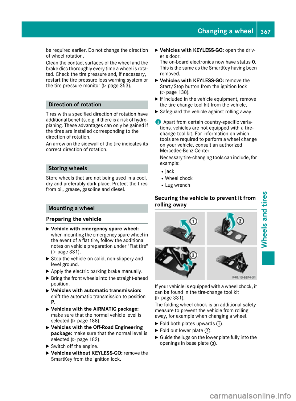
If your vehicle is equipped with a wheel chock, it
can be found in the tire-change tool kit
( Y
page 331).
The folding wheel chock is an additional safety
measure to prevent the vehicle from rolling
away, for example when changing a wheel. X
Fold both plates upwards C .X
Fold out lower plate D .X
Guide the lugs on the lower plate fully into the
openings in base plate
Page 370 of 390
X
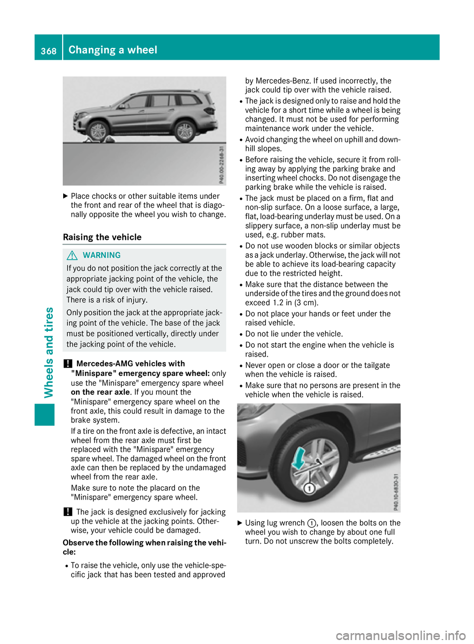
Place chocks or other suitable items under
the front and rear of the wheel that is diago-
nally opposite the wheel you wish to change.
Raising the vehicle
G WARNING
If you do not position the jack correctly at the
appropriate jacking point of the vehicle, the
jack could tip over with the vehicle raised.
There is a risk of injury.
Only position the jack at the appropriate jack-
ing point of the vehicle. The base of the jack
must be positioned vertically, directly under
the jacking point of the vehicle.
! Mercedes-AMG vehicles with
"Minispare" emergency spare wheel: only
use the "Minispare" emergency spare wheel
on the rear axle . If you mount the
"Minispare" emergency spare wheel on the
front axle, this could result in damage to the
brake system.
If a tire on the front axle is defective, an intact
wheel from the rear axle must first be
replaced with the "Minispare" emergency
spare wheel. The damaged wheel on the front
axle can then be replaced by the undamaged
wheel from the rear axle.
Make sure to note the placard on the
"Minispare" emergency spare wheel.
! The jack is designed exclusively for jacking
up the vehicle at the jacking points. Other-
wise, your vehicle could be damaged.
Observe the following when raising the vehi-
cle: R
To raise the vehicle, only use the vehicle-spe-
cific jack that has been tested and approved by Mercedes-Benz. If used incorrectly, the
jack could tip over with the vehicle raised. R
The jack is designed only to raise and hold the
vehicle for a short time while a wheel is being
changed. It must not be used for performing
maintenance work under the vehicle. R
Avoid changing the wheel on uphill and down-
hill slopes. R
Before raising the vehicle, secure it from roll-
ing away by applying the parking brake and
inserting wheel chocks. Do not disengage the
parking brake while the vehicle is raised. R
The jack must be placed on a firm, flat and
non-slip surface. On a loose surface, a large,
flat, load-bearing underlay must be used. On a
slippery surface, a non-slip underlay must be
used, e.g. rubber mats. R
Do not use wooden blocks or similar objects
as a jack underlay. Otherwise, the jack will not
be able to achieve its load-bearing capacity
due to the restricted height.R
Make sure that the distance between the
underside of the tires and the ground does not
exceed 1.2 in (3 cm). R
Do not place your hands or feet under the
raised vehicle. R
Do not lie under the vehicle. R
Do not start the engine when the vehicle is
raised. R
Never open or close a door or the tailgate
when the vehicle is raised. R
Make sure that no persons are present in the
vehicle when the vehicle is raised.
X
Using lug wrench C , loosen the bolts on the
wheel you wish to change by about one full
turn. Do not unscrew the bolts completely.368
Changing a wheel
Wheels and tires
Page 372 of 390
G WARNING
If you tighten the wheel bolts or wheel nuts
when the vehicle is raised, the jack could tip
over. There is a risk of injury.
Only tighten the wheel bolts or wheel nuts
when the vehicle is on the ground.
! To prevent damage to the paintwork, hold
the wheel securely against the wheel hub
while screwing in the first wheel bolt.
Always pay attention to the instructions and
safety notes in the "Changing a wheel" section
( Y
page 366).
Only use wheel bolts that have been designed
for the wheel and the vehicle. For safety rea-
sons, Mercedes-Benz recommends that you
only use wheel bolts which have been approved
for Mercedes-Benz vehicles and the respective
wheel.
! Always use wheel bolts D to mount the
"Minispare" emergency spare wheel. Using
other wheel bolts to mount the "Minispare"
emergency spare wheel could damage the
brake system.
C
Wheel bolts for all wheels supplied by the
factory and for the collapsible spare wheel
(Mercedes-AMG GLE 63)
D
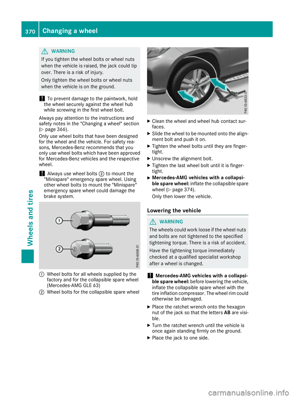
Wheel bolts for the collapsible spare wheel X
Clean the wheel and wheel hub contact sur-
faces. X
Slide the wheel to be mounted onto the align-
ment bolt and push it on. X
Tighten the wheel bolts until they are finger-
tight. X
Unscrew the alignment bolt. X
Tighten the last wheel bolt until it is finger-
tight. X
Mercedes-AMG vehicles with a collapsi-
ble spare wheel: inflate the collapsible spare
wheel ( Y
page 374).
Only then lower the vehicle.
Lowering the vehicle
G WARNING
The wheels could work loose if the wheel nuts
and bolts are not tightened to the specified
tightening torque. There is a risk of accident.
Have the tightening torque immediately
checked at a qualified specialist workshop
after a wheel is changed.
! Mercedes-AMG vehicles with a collapsi-
ble spare wheel: before lowering the vehicle,
inflate the collapsible spare wheel with the
tire inflation compressor. The wheel rim could
otherwise be damaged. X
Place the ratchet wrench onto the hexagon
nut of the jack so that the letters AB are visi-
ble. X
Turn the ratchet wrench until the vehicle is
once again standing firmly on the ground. X
Place the jack to one side.370
Changing a wheel
Wheels and tires
Page 374 of 390
Notes on the vehicle equipment – always equip
the vehicle: R
with tires of the same size on a given axle (left
and right) R
with the same type of tires at a given time
(summer tires, winter tires, MOExtended
tires)
Vehicles equipped with MOExtended tires are
not equipped with a TIREFIT kit at the factory. It
is therefore recommended that you additionally
equip your vehicle with a TIREFIT kit if you mount
tires that do not feature run-flat properties, e.g.
winter tires. A TIREFIT kit may be obtained from
a qualified specialist workshop.
Emergency spare wheel
Important safety notes
G WARNING
The wheel or tire size as well as the tire type of
the spare wheel or emergency spare wheel
and the wheel to be replaced may differ.
Mounting an emergency spare wheel may
severely impair the driving characteristics.
There is a risk of an accident.
To avoid hazardous situations: R
adapt your driving style accordingly and
drive carefully. R
never mount more than one spare wheel or
emergency spare wheel that differs in size. R
only use a spare wheel or emergency spare
wheel of a different size briefly. R
do not switch ESP ®
off.R
have a spare wheel or emergency spare
wheel of a different size replaced at the
nearest qualified specialist workshop.
Observe that the wheel and tire dimensions
as well as the tire type must be correct.
! Mercedes-AMG vehicles with
"Minispare" emergency spare wheel: only
use the "Minispare" emergency spare wheel
on the rear axle . If you mount the
"Minispare" emergency spare wheel on the
front axle, this could result in damage to the
brake system. If a tire on the front axle is defective, an intact
wheel from the rear axle must first be
replaced with the "Minispare" emergency
spare wheel. The damaged wheel on the front
axle can then be replaced by the undamaged
wheel from the rear axle.
Make sure to note the placard on the
"Minispare" emergency spare wheel.
When using an emergency spare wheel or spare
wheel of a different size, you must not exceed
the maximum speed of 50 mph (80 km/h).
Snow chains must not be mounted on emer-
gency spare wheels.
General notes You can ask for information regarding permitted
emergency spare wheels at an authorized
Mercedes-Benz Center.
Mounting the emergency spare wheel is descri-
bed under "Mounting a wheel" ( Y
page 367).
You should regularly check the pressure of the
emergency spare wheel, particularly prior to
long trips, and correct the pressure as neces-
sary ( Y
page 349). The value on the wheel is
valid.
An emergency spare wheel may also be moun-
ted against the direction of rotation. Observe
the time restriction on use as well as the speed
limitation specified on the emergency spare
wheel.
Replace the tires after six years at the latest,
regardless of wear. This also applies to the
emergency spare wheel.
When you are driving with the collapsible spare
wheel mounted, the tire pressure loss warning
system or the tire pressure monitor cannot func-
tion reliably. Only restart the tire pressure loss
warning system or tire pressure monitor when
the defective wheel has been replaced with a
new wheel.
Vehicles with tire pressure monitor: after
mounting an emergency spare wheel, the sys-
tem may still display the tire pressure of the
removed wheel for a few minutes. The value dis-
played for the mounted emergency spare wheel
is not the same as the current tire pressure of
the emergency spare wheel.372
Emergency spare wheel
Wheels and tires