2017 MERCEDES-BENZ GLS display
[x] Cancel search: displayPage 324 of 390
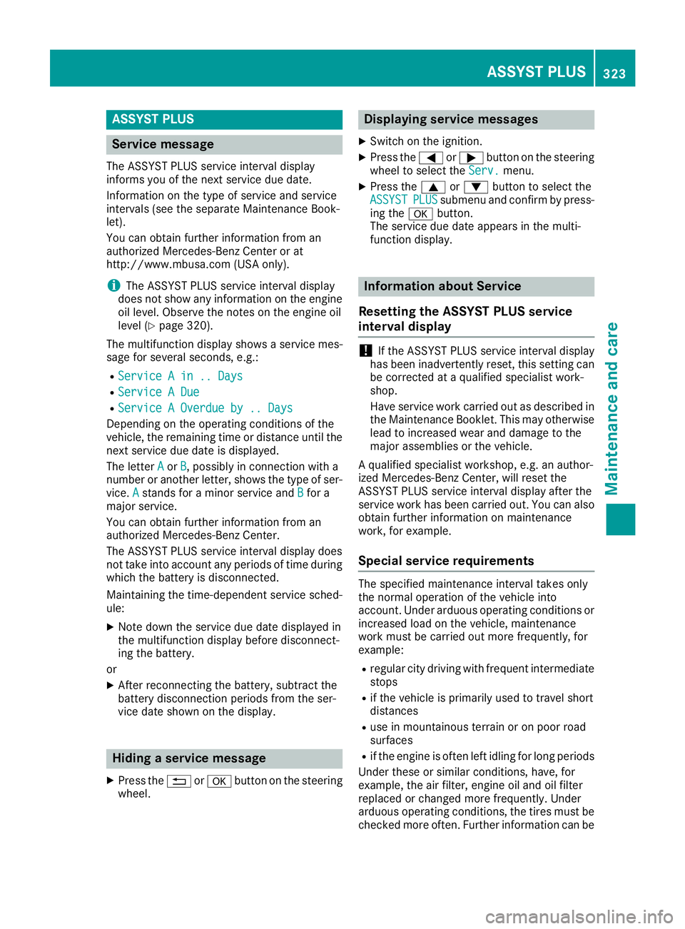
Where possible, let the engine cool down and
touch only the components described in the
following.
G WARNING
The cooling system is pressurized, particularly
when the motor is warm. If you open the cap,
you could be scalded if hot coolant sprays out.
There is a risk of injury.
Let the engine cool down before you open the
cap. Wear gloves and eye protection. Slowly
open the cap to relieve pressure.
G WARNING
Windshield washer concentrate could ignite if
it comes into contact with hot engine compo-
nents or the exhaust system. There is a risk of
fire and injury.
Make sure that no windshield washer con-
centrate is spilled next to the filler neck.
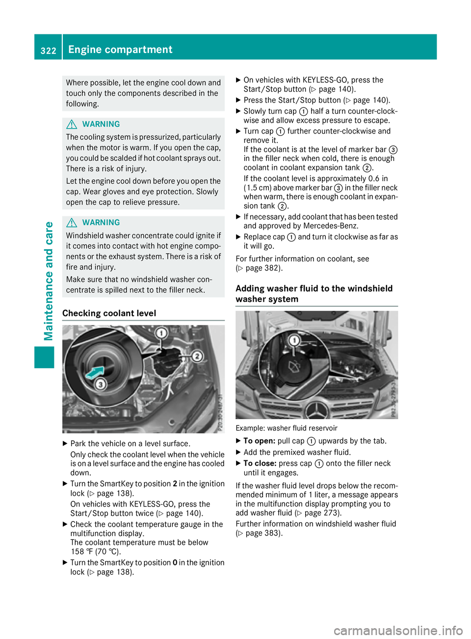
Checking coolant level
X
Park the vehicle on a level surface.
Only check the coolant level when the vehicle
is on a level surface and the engine has cooled
down. X
Turn the SmartKey to position 2 in the ignition
lock ( Y
page 138).
On vehicles with KEYLESS-GO, press the
Start/Stop button twice ( Y
page 140).X
Check the coolant temperature gauge in the
multifunction display.
The coolant temperature must be below
158 ‡ (70 †). X
Turn the SmartKey to position 0 in the ignition
lock ( Y
page 138). X
On vehicles with KEYLESS-GO, press the
Start/Stop button ( Y
page 140).X
Press the Start/Stop button ( Y
page 140).X
Slowly turn cap �C half a turn counter-clock-
wise and allow excess pressure to escape. X
Turn cap �C further counter-clockwise and
remove it.
If the coolant is at the level of marker bar �
Page 325 of 390
ASSYST PLUS
Service message The ASSYS T PLU S servic e interval display
inform s you of th e next servic e due date.
Information on th e typ e of servic e and servic e
intervals (see th e separat e Maintenance Book -
let).
You can obtain further information from an
authorize d Mercedes-Benz Cente r or at
http://www.mbusa.co m (US A only).
i The ASSYS T PLU S servic e interval display
does no t sho w any information on th e engin e
oil level. Observ e th e note s on th e engin e oil
level ( Y
page 320).
The multifunction display shows a servic e mes -
sage for several seconds, e.g. :R
Servic e A in .. Day sR
Servic e A DueR
Servic e A Overdu e by .. Day s
Dependin g on th e operating condition s of th e
vehicle, th e remaining time or distanc e until th e
next servic e due dat e is displayed.
The lette r A or B , possibl y in connection wit h a
number or another letter, shows th e typ e of ser -
vice. A stand s for a minor servic e and B for a
major service.
You can obtain further information from an
authorize d Mercedes-Benz Center.
The ASSYS T PLU S servic e interval display does
no t tak e int o accoun t any periods of time during
whic h th e battery is disconnected.
Maintainin g th e time-dependen t servic e sched-
ule: X
Not e down th e servic e due dat e displayed in
th e multifunction display before disconnect -
ing th e battery.
or X
Afte r reconnecting th e battery, subtrac t th e
battery disconnection periods from th e ser -
vic e dat e shown on th e display.
Hiding a service message X
Press th e �8 or �v butto n on th e steering
wheel. Displaying service messages X
Switc h on th e ignition .X
Press th e �Y or �e butto n on th e steering
whee l to select th e Serv. menu.X
Press th e �c or �d butto n to select th e
ASSYST PLU S submen u and confirm by press-
ing th e �v button.
The servic e due dat e appear s in th e multi-
function display.
Infor ma ti on about Service
Resetting the ASSYST PLUS service
interval display
! If th e ASSYS T PLU S servic e interval display
has been inadvertentl y reset , this setting can
be correcte d at a qualified specialist work-
shop.
Hav e servic e wor k carrie d out as described in
th e Maintenance Booklet . This may otherwise
lead to increased wear and damag e to th e
major assemblies or th e vehicle.
A qualified specialist workshop , e.g. an author-
ized Mercedes-Benz Center, will reset th e
ASSYS T PLU S servic e interval display after th e
servic e wor k has been carrie d out . You can also
obtain further information on maintenance
work, for example.
Special service requirements The specifie d maintenance interval takes only
th e normal operation of th e vehicl e int o
account. Under arduous operating condition s or
increased load on th e vehicle, maintenance
wor k mus t be carrie d out mor e frequently, for
example: R
regular cit y drivin g wit h frequen t intermediat e
stops R
if th e vehicl e is primarily used to travel short
distances R
use in mountainous terrain or on poor road
surfaces R
if th e engin e is often lef t idlin g for lon g periods
Under these or similar conditions, have, for
example, th e air filter, engin e oil and oil filter
replace d or changed mor e frequently. Under
arduous operating conditions, th e tires mus t be
checke d mor e often . Further information can beASSYST PLUS 323
Maintenance and care Z
Page 331 of 390
Cleaning the trailer tow hitch
H Environmental note
Dispose of rags soaked in oil and grease in an
environmentally responsible manner.
! Do not clean the ball coupling with a power
washer. Do not use solvents.
! Please note the care instructions in the
trailer coupling manufacturer's operating
instructions.
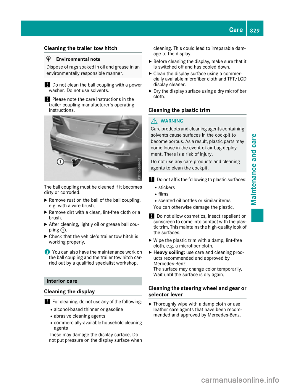
The ball coupling must be cleaned if it becomes
dirty or corroded. X
Remove rust on the ball of the ball coupling,
e.g. with a wire brush. X
Remove dirt with a clean, lint-free cloth or a
brush. X
After cleaning, lightly oil or grease ball cou-
pling �C .X
Check that the vehicle's trailer tow hitch is
working properly.
i You can also have the maintenance work on
the ball coupling and the trailer tow hitch car-
ried out by a qualified specialist workshop.
Interior care
Cleaning the display
! For cleaning, do not use any of the following: R
alcohol-based thinner or gasoline R
abrasive cleaning agents R
commercially-available household cleaning
agents
These may damage the display surface. Do
not put pressure on the display surface when cleaning. This could lead to irreparable dam-
age to the display. X
Before cleaning the display, make sure that it
is switched off and has cooled down. X
Clean the display surface using a commer-
cially available microfiber cloth and TFT/LCD
display cleaner. X
Dry the display surface using a dry microfiber
cloth.
Cleaning the plastic trim
G WARNING
Care products and cleaning agents containing
solvents cause surfaces in the cockpit to
become porous. As a result, plastic parts may
come loose in the event of air bag deploy-
ment. There is a risk of injury.
Do not use any care products and cleaning
agents to clean the cockpit.
! Do not affix the following to plastic surfaces: R
stickers R
films R
scented oil bottles or similar items
You can otherwise damage the plastic.
! Do not allow cosmetics, insect repellent or
sunscreen to come into contact with the plas-
tic trim. This maintains the high-quality look of
the surfaces. X
Wipe the plastic trim with a damp, lint-free
cloth, e.g. a microfiber cloth. X
Heavy soiling: use care and cleaning prod-
ucts recommended and approved by
Mercedes-Benz.
The surface may change color temporarily.
Wait until the surface is dry again.
Cleaning the steering wheel and gear or
selector lever X
Thoroughly wipe with a damp cloth or use
leather care agents that have been recom-
mended and approved by Mercedes-Benz. Care 329
Maintenance and care Z
Page 334 of 390
X
If possible, bring the front wheels into the
straight-ahead position. X
Vehicles with the AIRMATIC package:
make sure that the normal vehicle level is
selected ( Y
page 188).X
Vehicles with the Off-Road Engineering
package: make sure that the normal level is
selected ( Y
page 182).X
Switch off the engine. X
Vehicles without KEYLESS-GO: remove the
SmartKey from the ignition lock. X
Vehicles with KEYLESS-GO: open the driv-
er's door.
The on-board electronics now have status 0 .
This is the same as the SmartKey having been
removed. X
Vehicles with KEYLESS-GO: remove the
Start/Stop button from the ignition lock
( Y
page 138).X
Make sure that the passengers are not endan-
gered as they do so. Make sure that no one is
near the danger area while a wheel is being
changed. Anyone who is not directly assisting
in the wheel change should, for example,
stand behind the barrier. X
Get out of the vehicle. Pay attention to traffic
conditions when doing so. X
Close the driver's door. X
Unload heavy luggage.
i Only operate the tire inflation compressor
using a 12 V socket, even if the ignition is
turned off ( Y
page 306).
An emergency cut-out ensures that the on-
board voltage does not drop too low. If the on-
board voltage is too low, the power to the
sockets is automatically cut. This ensures
that there is sufficient power to start the
engine.
MOExtended tires (tires with run-flat
properties)
General notes
With MOExtended tires (tires with run flat char-
acteristics), you can continue to drive your vehi-
cle even if there is a total loss of pressure in one
or more tires. The affected tire must not show
any clearly visible damage.
You can recognize MOExtended tires by the
MOExtended marking which appears on the sidewall of the tire. You will find this marking
next to the tire size designation, the load-bear-
ing capacity and the speed index ( Y
page 361).
MOExtended tires may only be used in conjunc-
tion with an active tire pressure loss warning
system or with an active tire pressure monitor.
If a pressure loss warning message appears
in the multifunction display: R
observe the instructions in the display mes-
sages ( Y
page 268). R
check the tire for damage. R
if driving on, observe the following notes.
The driving distance possible in run-flat mode is
approximately 50 miles (80 km) when the vehi-
cle is partially laden and approximately 18 miles
(30 km) when the vehicle is fully laden.
In addition to the vehicle load, the driving dis-
tance possible depends upon: R
vehicle speed R
road condition R
outside temperature
The driving distance possible in run-flat mode
may be reduced by extreme driving conditions
or maneuvers, or it can be increased through a
moderate style of driving.
The driving distance possible in run-flat mode is
counted from the moment the tire pressure loss
warning appears in the multifunction display.
You must not exceed a maximum speed of
50 mph (80 km/h).
i When replacing one or all tires, please
observe the following specifications for your
vehicle's tires: R
size R
type and R
the "MOExtended" mark
If a tire has gone flat and cannot be replaced
with a MOExtended tire, a standard tire may
be used as a temporary measure. Make sure
that you use the proper size and type (sum-
mer or winter tire).
i Vehicles equipped with MOExtended tires
are not equipped with a TIREFIT kit at the fac-
tory. It is therefore recommended that you
additionally equip your vehicle with a TIR EFIT
kit if you mount tires that do not feature run-
flat properties, e.g. winter tires. A TIREFIT kit
may be obtained from a qualified specialist
workshop.332
Flat tire
Breakdown assistance
Page 354 of 390
Avoid tire pressures that are too high in all the
tires, including the spare wheel.
Overinflated tires may: R
increase the braking distance R
adversely affect handling R
wear excessively and/or unevenly R
have an adverse effect on ride comfort R
be more susceptible to damage
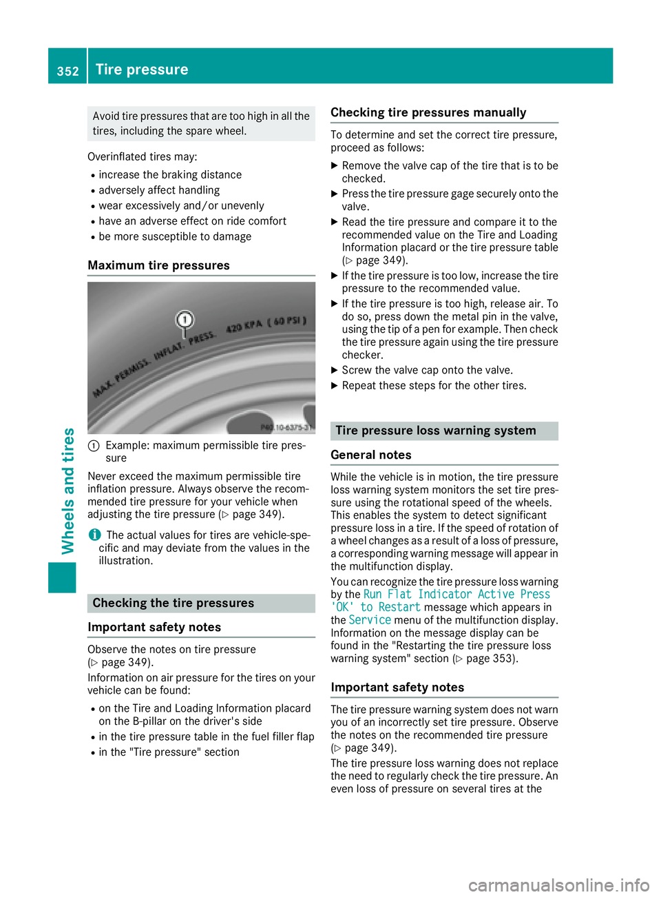
Maximum tire pressures
�C
Example: maximum permissible tire pres-
sure
Never exceed the maximum permissible tire
inflation pressure. Always observe the recom-
mended tire pressure for your vehicle when
adjusting the tire pressure ( Y
page 349).
i The actual values for tires are vehicle-spe-
cific and may deviate from the values in the
illustration.
Checking the tire pressures
Important safety notes Observe the notes on tire pressure
( Y
page 349).
Information on air pressure for the tires on your
vehicle can be found: R
on the Tire and Loading Information placard
on the B-pillar on the driver's side R
in the tire pressure table in the fuel filler flap R
in the "Tire pressure" section Checking tire pressures manually To determine and set the correct tire pressure,
proceed as follows: X
Remove the valve cap of the tire that is to be
checked. X
Press the tire pressure gage securely onto the
valve. X
Read the tire pressure and compare it to the
recommended value on the Tire and Loading
Information placard or the tire pressure table
( Y
page 349). X
If the tire pressure is too low, increase the tire
pressure to the recommended value. X
If the tire pressure is too high, release air. To
do so, press down the metal pin in the valve,
using the tip of a pen for example. Then check
the tire pressure again using the tire pressure
checker. X
Screw the valve cap onto the valve. X
Repeat these steps for the other tires.
Tire pressure loss warning system
General notes While the vehicle is in motion, the tire pressure
loss warning system monitors the set tire pres-
sure using the rotational speed of the wheels.
This enables the system to detect significant
pressure loss in a tire. If the speed of rotation of
a wheel changes as a result of a loss of pressure,
a corresponding warning message will appear in
the multifunction display.
You can recognize the tire pressure loss warning
by the Run Flat Indicator Active Press
'OK' to Restart message which appears in
the Service menu of the multifunction display.
Information on the message display can be
found in the "Restarting the tire pressure loss
warning system" section ( Y
page 353).
Important safety notes
The tire pressure warning system does not warn
you of an incorrectly set tire pressure. Observe
the notes on the recommended tire pressure
( Y
page 349).
The tire pressure loss warning does not replace
the need to regularly check the tire pressure. An
even loss of pressure on several tires at the352
Tire pressure
Wheels and tires
Page 355 of 390
same time cannot be detected by the tire pres-
sure loss warning system.
The tire pressure monitor is not able to warn you
of a sudden loss of pressure, e.g. if the tire is
penetrated by a foreign object. In the event of a
sudden loss of pressure, bring the vehicle to a
halt by braking carefully. Avoid abrupt steering
movements.
The function of the tire pressure loss warning
system is limited or delayed if: R
snow chains are mounted on your vehicle's
tires. R
road conditions are wintry. R
you are driving on sand or gravel. R
you adopt a very sporty driving style (corner-
ing at high speeds or driving with high rates of
acceleration). R
you are driving with a heavy load (in the vehi-
cle or on the roof).
Restarting the tire pressure loss warn-
ing system Restart the tire pressure loss warning system if
you have: R
changed the tire pressure R
changed the wheels or tires R
mounted new wheels or tires X
Before restarting, make sure that the tire
pressures are set properly on all four tires for
the respective operating conditions.
The recommended tire pressure can be found
on the Tire and Loading Information placard
on the B-pillar. Additionally, a tire pressure
table is attached to the fuel filler flap. The tire
pressure loss warning system can only give
reliable warnings if you have set the correct
tire pressure. If an incorrect tire pressure is
set, these incorrect values will be monitored. X
Also observe the notes in the section on tire
pressures ( Y
page 349).X
Make sure that the SmartKey is in position 2
in the ignition lock ( Y
page 138).X
Press the �Y or �e button on the steering
wheel to select the Service menu.X
Press the �c or �d button to select
Tire Pressure .X
Press the �v button.
The Run Flat Indicator Active Press
'OK' to Restart message appears in the
multifunction display. If you wish to confirm the restart: X
Press the �v button.
The Tire Pressure Now OK? message
appears in the multifunction display. X
Press the �c or �d button to select Yes .X
Press the �v button.
The Run Flat Indicator Restarted mes-
sage appears in the multifunction display.
After a teach-in period, the tire pressure loss
warning system will monitor the set tire pres-
sures of all four tires.
If you wish to cancel the restart: X
Press the �8 button.
or X
When the Tire Pressure Now OK? message
appears, press the �c or �d button to
select Cancel . X
Press the �v button.
The tire pressure values stored at the last
restart will continue to be monitored.
Tire pressure monitor
General notes If a tire pressure monitor is installed, the vehi-
cle's wheels have sensors that monitor the tire
pressures in all four tires. The tire pressure mon-
itor warns you if the pressure drops in one or
more of the tires. The tire pressure monitor only
functions if the corresponding sensors are
installed in all wheels.
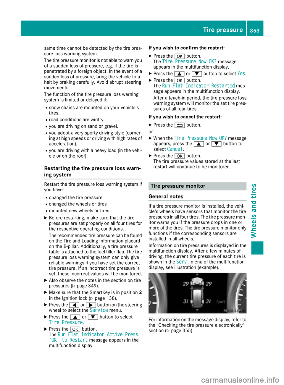
Information on tire pressures is displayed in the
multifunction display. After a few minutes of
driving, the current tire pressure of each tire is
shown in the Serv. menu of the multifunction
display, see illustration (example).
For information on the message display, refer to
the "Checking the tire pressure electronically"
section ( Y
page 355).Tire pressure 353
Wheels and tires Z
Page 357 of 390
In addition to the warning lamp, a message
appears in the multifunction display. Observe
the information on display messages
( Y
page 268).
It may take up to ten minutes for a malfunction
of the tire pressure monitor to be indicated. A
malfunction will be indicated by the tire pres-
sure warning lamp flashing for approximately
one minute and then remaining lit. When the
malfunction has been rectified, the tire pressure
warning lamp goes out after a few minutes of
driving.
The tire pressure values indicated by the on-
board computer may differ from those meas-
ured at a gas station with a pressure gauge. The
tire pressures shown by the on-board computer
refer to those measured at sea level. At high
altitudes, the tire pressure values indicated by a
pressure gauge are higher than those shown by
the on-board computer. In this case, do not
reduce the tire pressures.
The operation of the tire pressure monitor can
be affected by interference from radio transmit-
ting equipment (e.g. radio headphones, two-way
radios) that may be being operated in or near the
vehicle.
Checking the tire pressure electroni-
cally X
Make sure that the SmartKey is in position 2
in the ignition lock ( Y
page 138).X
Press the �Y or �e button on the steering
wheel to select the Serv. menu.X
Press the �c or �d button to select
Tire Pressure .X
Press the �v button.
The current tire pressure of each tire is shown
in the multifunction display.
If the vehicle has been parked for longer than
20 minutes, the Tire pressure will be
displayed after driving a few minutes
message appears.
After a teach-in process, the tire pressure mon-
itor automatically detects new wheels or new
sensors. As long as a clear allocation of the tire
pressure value to the individual wheels is not
possible, the Tire Pressure Monitor Active
display message is shown instead of the tire
pressure display. The tire pressures are already
being monitored.
If an emergency spare wheel is mounted, the
system may continue to show the tire pressure of the wheel that has been removed for a few
minutes. If this occurs, note that the value dis-
played for the position where the spare wheel is
mounted is not the same as the current tire
pressure of the emergency spare wheel.
Tire pressure monitor warning mes-
sages If the tire pressure monitor detects a pressure
loss in one or more tires, a warning message is
shown in the multifunction display. The yellow
tire pressure warning lamp then lights up. R
If the Please Correct Tire Pressure
message appears in the multifunction display,
the tire pressure in at least one tire is too low.
The tire pressure must be corrected when the
opportunity arises. R
If the Check Tires message appears in the
multifunction display, the tire pressure in at
least one tire has dropped significantly. The
tires must be checked. R
If the Warning Tire Malfunction message
appears in the multifunction display, the tire
pressure in at least one tire has dropped sud-
denly. The tires must be checked.
Be sure to observe the instructions and safety
notes in the display messages in the "Tires" sec-
tion ( Y
page 268).
If the wheel positions on the vehicle are rotated,
the tire pressures may be displayed for the
wrong positions for a short time. This is rectified
after a few minutes of driving, and the tire pres-
sures are displayed for the correct positions.
Restarting the tire pressure monitor When you restart the tire pressure monitor, all
existing warning messages are deleted and the
warning lamps go out. The monitor uses the cur-
rently set tire pressures as the reference values
for monitoring. In most cases, the tire pressure
monitor will automatically detect the new refer-
ence values after you have changed the tire
pressure. However, you can also define refer-
ence values manually as described here. The tire
pressure monitor then monitors the new tire
pressure values. X
Set the tire pressure to the value recommen-
ded for the corresponding driving situation on
the Tire and Loading Information placard on
the driver's side B-pillar ( Y
page 349).Tire pressure 355
Wheels and tires Z
Page 358 of 390
You can find more tire pressure values for
various operating conditions in the tire pres-
sure table inside the fuel filler flap
( Y
page 349).X
Make sure that the tire pressure is correct on
all four wheels. X
Make sure that the SmartKey is in position 2
in the ignition lock. X
Press the �Y or �e button on the steering
wheel to select the Serv. menu.X
Press the �c or �d button to select
Tire Pressure .X
Press the �v button.
The multifunction display shows the current
tire pressure for the individual tires or the
Tire pressure will be displayed
after driving a few minutes message.X
Press the �d button.
The Use Current Pressures as New Ref‐
erence Values message appears in the mul-
tifunction display.
If you wish to confirm the restart: X
Press the �v button.
The Tire Press. Monitor Restarted mes-
sage appears in the multifunction display.
After driving for a few minutes, the system
checks whether the current tire pressures are
within the specified range. The new tire pres-
sures are then accepted as reference values
and monitored.
If you wish to cancel the restart: X
Press the �8 button.
The tire pressure values stored at the last
restart will continue to be monitored.
Radio type approval for the tire pres-
sure monitor Country Radio type approval number
USA FCC ID: MRXMW2433A
FCC ID: MRXGG4
FCC ID: MRXMC34MA4
Canada IC: 2546A-MW2433A
IC: 2546A-GG4
IC: 2546A-MC34MA4 Loading the vehicle
Instruction labels for tires and loads
G WARNING
Overloaded tires can overheat, causing a
blowout. Overloaded tires can also impair the
steering and driving characteristics and lead
to brake failure. There is a risk of accident.
Observe the load rating of the tires. The load
rating must be at least half of the GAWR of
your vehicle. Never overload the tires by
exceeding the maximum load.
Two instruction labels on your vehicle show the
maximum possible load.
(1) The Tire and Loading Information placard is
on the B-pillar on the driver's side. The Tire
and Loading Information placard shows the
maximum permissible number of occu-
pants and the maximum permissible vehicle
load. It also contains details of the tire sizes
and corresponding pressures for tires
mounted at the factory.
(2) The vehicle identification plate is on the B-
pillar on the driver's side. The vehicle iden-
tification plate informs you of the gross
vehicle weight rating. It is made up of the
vehicle weight, all vehicle occupants, the
fuel and the cargo. You can also find infor-
mation about the maximum gross axle
weight rating on the front and rear axle.
The maximum gross axle weight rating is
the maximum weight that can be carried by
one axle (front or rear axle). Never exceed
the maximum load or the maximum gross
axle weight rating for the front or rear axle.356
Loading the vehicle
Wheels and tires