2017 MERCEDES-BENZ GLE43AMG SUV center console
[x] Cancel search: center consolePage 283 of 366

include such items as chargers for mobile
phones.
If you use the sockets for long periods when the
engine is switched off, the battery may dis-
charge.
iAn emergency cut-out ensures that the on-
board voltage does not drop too low. If the on-
board voltage is too low, the power to the
sockets is automatically cut. This ensures
that there is sufficient power to start the
engine.
Socket in the front center console
!The socket is not suitable for operating the
tire inflation compressor.
XTo open: slide the cover to its foremost posi-
tion.
XLift up the cover of the socket.
XTo close: pull the cover back as far as it will
go.
Socket in the rear compartment center
console
Vehicles with the Rear Seat Entertainment Sys-
tem have two sockets in the center console in
the rear compartment.
XLift up the cover of the socket.
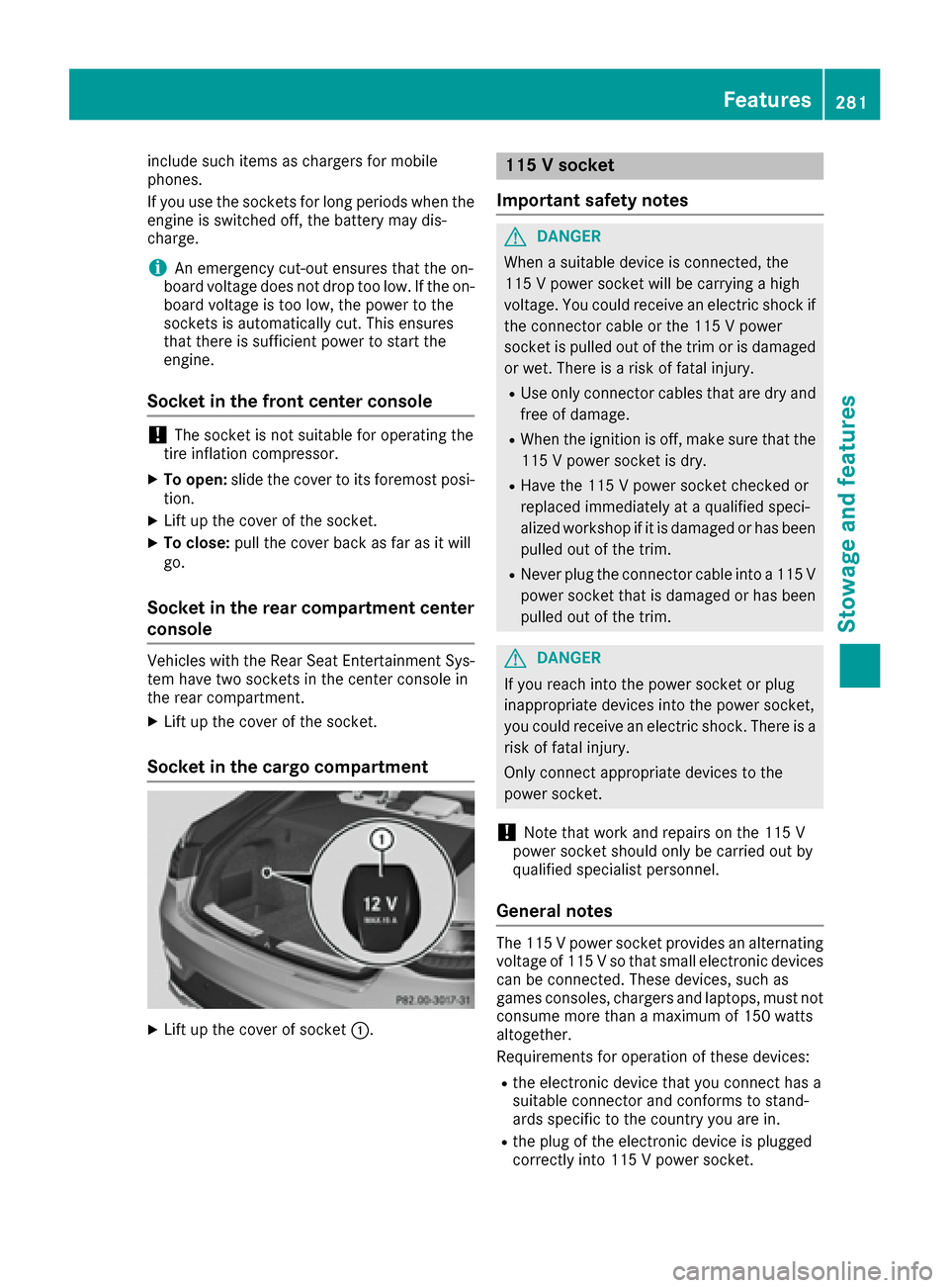
Socket in the cargo compartment
XLift up the cover of socket :.
115 V socket
Important safety notes
GDANGER
When a suitable device is connected, the
115 V power socket will be carrying a high
voltage. You could receive an electric shock if the connector cable or the 115 V power
socket is pulled out of the trim or is damaged
or wet. There is a risk of fatal injury.
RUse only connector cables that are dry and
free of damage.
RWhen the ignition is off, make sure that the
115 V power socket is dry.
RHave the 115 V power socket checked or
replaced immediately at a qualified speci-
alized workshop if it is damaged or has been
pulled out of the trim.
RNever plug the connector cable into a 115 V
power socket that is damaged or has been
pulled out of the trim.
GDANGER
If you reach into the power socket or plug
inappropriate devices into the power socket,
you could receive an electric shock. There is a
risk of fatal injury.
Only connect appropriate devices to the
power socket.
!Note that work and repairs on the 115 V
power socket should only be carried out by
qualified specialist personnel.
General notes
The 115 Vpower socket provides an alternating
voltage of 115 V so that small electronic devices
can be connected. These devices, such as
games consoles, chargers and laptops, must not consume more than a maximum of 150 watts
altogether.
Requirements for operation of these devices:
Rthe electronic device that you connect has a
suitable connector and conforms to stand-
ards specific to the country you are in.
Rthe plug of the electronic device is plugged
correctly into 115 V power socket.
Features281
Stowage and features
Z
Page 311 of 366

XAffix part:of the TIREFIT sticker to the
instrument cluster within the driver's field of
vision.
XAffix part ;of the TIREFIT sticker near the
valve on the wheel with the defective tire.
XPull connector ?with the cable and hose A
out of the tire inflation compressor housing.
XScrew hose Aonto flange Bof tire sealant
bottle :.
XPlace tire sealant bottle :head downwards
into recess ;of the tire inflation compres-
sor.
XRemove the cap from valve Con the faulty
tire.
XScrew filler hose Donto valve C.
XInsert connector ?into the socket in the
center console in the rear compartment or in
the socket in the cargo compartment.
Socket in the rear compartment:
(
Ypage 281)
Socket in the cargo compartment:
(
Ypage 281)
Only operate the tire inflation compressor
using the socket in the rear compartment or
in the cargo compartment, even if the ignition
is turned off. An emergency cut-out ensures that the on-
board voltage does not drop too low. If the on-
board voltage is too low, the power to the
sockets is automatically cut. This ensures
that there is sufficient power to start the
engine.
Observe the further information on sockets
(
Ypage 280).
XTurn the SmartKey to position
1in the ignition
lock (Ypage 125).
XPress on and off switch =on the tire inflation
compressor to I.
The tire inflation compressor is switched on.
The tire is inflated.
First, tire sealant is pumped into the tire. The
pressure may briefly rise to approximately
500 kPa (5 bar/73 psi).
Do not switch off the tire inflation com-
pressor during this phase.
XLet the tire inflation compressor run for a
maximum of five minutes. The tire should then
have attained a pressure of at lea
st 180 kPa
(1.8 bar/26 psi).
If a pressure of 180 kPa (1.8 bar/26 psi) has
been attained after five minutes, see "Tire pres-
sure reached" (
Ypage 310).
If a tire pressure of 180 kPa (1.8 ba r/26 psi) has
not been attained after five minutes, see "Tire
pressure not reached" (
Ypage 309).
If tire sealant has escaped, clean it off affected
areas as quickly as possible. Use plain water if
possible.
If your clothes are soiled with tire sealant, have
them cleaned with perchloroethylene at a dry
cleaner as soon as possible.
Tire pressure not reached
If a pressure of 180 kPa (1.8 bar/26 psi) has not
been attained after five minutes:
XSwitch off the tire inflation compressor.
XUnscrew the filler hose from the valve of the
faulty tire.
Note that tire sealant may escape when you
unscrew the filler hose.
XVery slowly drive forwards or reverse approx-
imately 30 ft (10 m).
XPump up the tire again.
After a maximum of five minutes the tire pres- sure must be at least 180 kPa (1.8 bar/
26 psi).
Flat tire309
Breakdown assistance
Z
Page 351 of 366

Inflating the collapsible spare wheel
(Mercedes-AMG GLE 63)
!
Inflat eth ecollapsible spar ewhee lusin gth e
tire inflation compressor before lowering th e
vehicle. The whee lrim could otherwise be
damaged.
!Do no toperate th etire inflation compressor
for longer than eigh tminute sat atime without
a break. It may otherwise overheat.
The tire inflation compressor can be operate d
again once it has cooled down .
Comply wit hth emanufacturer' ssafet yinstruc-
tion son th etire inflation compressor label and
on th etire sealan tbottle.
XMoun tth ecollapsible spar ewhee las descri-
bed (Ypage 341).
The collapsible spar ewhee lmust be mounte d
before it is inflated.
XRemove th etire inflation compressor from
th estowage spac eunder th etrunk floor
(
Ypage 306).
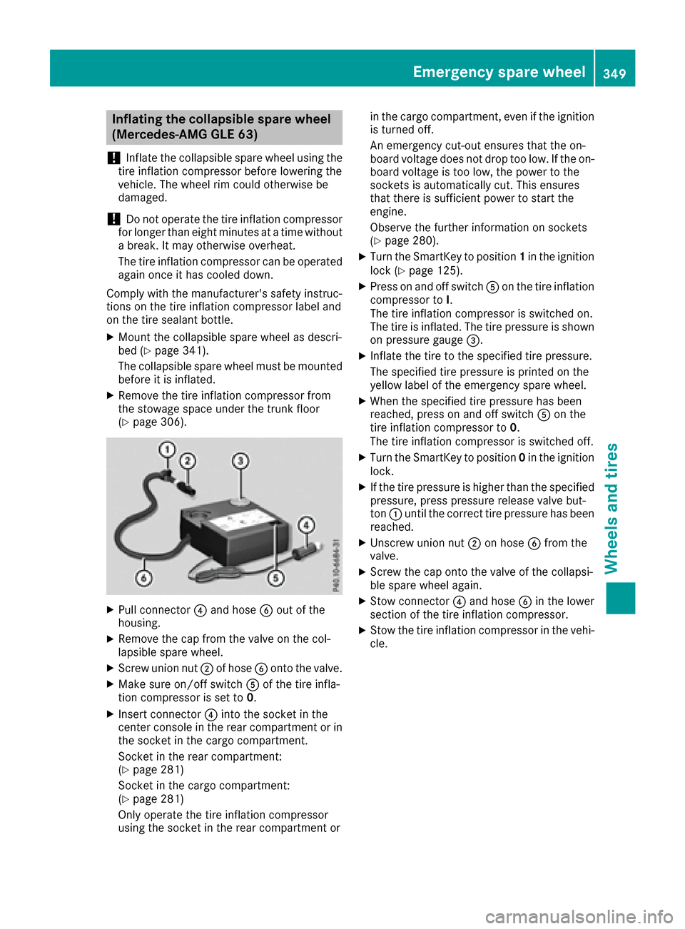
XPull connecto r? and hos eB out of th e
housing .
XRemove th ecap from th evalv eon th ecol-
lapsible spar ewheel.
XScrew unio nnut ;of hos eB onto th evalve.
XMak esur eon/off switch Aof th etire infla-
tion compressor is set to 0.
XInsertconnecto r? intoth esocke tin th e
center console in th erear compartmen tor in
th esocke tin th ecargo compartment.
Socket in th erear compartment:
(
Ypage 281)
Socket in th ecargo compartment:
(
Ypage 281)
Only operate th etire inflation compressor
usin gth esocke tin th erear compartmen tor in th
ecargo compartment, eve nif th eignition
is turne doff .
An emergenc ycut-out ensures that th eon -
boar dvoltag edoes no tdro pto olow. If th eon -
boar dvoltag eis to olow, th epower to th e
sockets is automatically cut .This ensures
that there is sufficien tpower to start th e
engine.
Observ eth efurther information on sockets
(
Ypage 280).
XTurn th eSmartKey to position 1in th eignition
loc k (Ypage 125).
XPress on and off switch Aon th etire inflation
compressor to I.
The tire inflation compressor is switched on .
The tire i
s inflated. The tire pressur eis shown
on pressur egauge =.
XInflateth etire to th especifie dtire pressure.
The specifie dtire pressur eis printe don th e
yellow label of th eemergenc yspar ewheel.
XWhen th especifie dtire pressur ehas been
reached, press on and off switch Aon th e
tire inflation compressor to 0.
The tire inflation compressor is switched off .
XTurn theSmartKey to position 0in th eignition
lock.
XIf th etire pressur eis higher than th especifie d
pressure, press pressur erelease valv ebut -
to n: until th ecorrec ttire pressur ehas been
reached.
XUnscrew unio nnut ;on hos eB from th e
valve.
XScrew th ecap onto th evalv eof th ecollapsi-
ble spar ewhee lagain .
XStow connecto r? and hos eB in th elower
section of th etire inflation compressor.
XStow th etire inflation compressor in th evehi-
cle .
Emergency spare wheel349
Wheels and tires
Z