2017 MERCEDES-BENZ GLE COUPE lock
[x] Cancel search: lockPage 333 of 366
You can find more tire pressure values for
various operating conditions in the tire pres-
sure table inside the fuel filler flap
(
Ypage 324).
XMake sure that the tire pressure is correct on
all four wheels.
XMake sure that the SmartKey is in position2
in the ignition lock.
XPress the =or; button on the steering
wheel to select the Serv.menu.
XPress the9or: button to select
Tire Pressure.
XPress the abutton.
The multifunction display shows the current
tire pressure for the individual tires or the
Tire pressure will be displayed
after driving a few minutesmessage.
XPress the :button.
The UseCurrentPressuresasNewRef‐erenceValuesmessage appears in the mul-
tifunction display.
If you wish to confirm the restart:
XPress the abutton.
The TirePress.MonitorRestartedmes-
sage appears in the multifunction display.
After driving for a few minutes, the system
checks whether the current tire pressures are
within the specified range. The new tire pres-
sures are then accepted as reference values
and monitored.
If you wish to cancel the restart:
XPress the %button.
The tire pressure values stored at the last
restart will continue to be monitored.
Radio type approval for the tire pres-
sure monitor
CountryRadio type approval number
USAFCC ID: MRXMW2433A
FCC ID: MRXGG4
FCC ID: MRXMC34MA4
CanadaIC: 2546A-MW2433A
IC: 2546A-GG4
IC: 2546A-MC34MA4
Loading the vehicle
Instruction labels for tires and loads
GWARNING
Overloaded tires can overheat, causing a
blowout. Overloaded tires can also impair the steering and driving characteristics and lead
to brake failure. There is a risk of accident.
Observe the load rating of the tires. The load
rating must be at least half of the GAWR of
your vehicle. Never overload the tires by
exceeding the maximum load.
Two instruction labels on your vehicle show the maximum possible load.
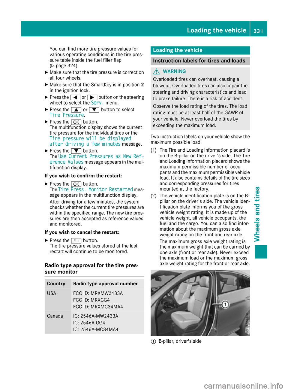
(1) The Tire and Loading Information placard is on the B-pillar on the driver's side. The Tire
and Loading Information placard shows the
maximum permissible number of occu-
pants and the maximum permissible vehicle
load. It also contains details of the tire sizes
and corresponding pressures for tires
mounted at the factory.
(2) The vehicle identification plate is on the B- pillar on the driver's side. The vehicle iden-
tification plate informs you of the gross
vehicle weight rating. It is made up of the
vehicle weight, all vehicle occupants, the
fuel and the cargo. You can also find infor-
mation about the maximum gross axle
weight rating on the front and rear axle.
The maximum gross axle weight rating is
the maximum weight that can be carried by
one axle (front or rear axle). Never exceed
the maximum load or the maximum gross
axle weight rating for the front or rear axle.
:B-pillar, driver's side
Loading the vehicle331
Wheels and tires
Z
Page 343 of 366
Changing a wheel
Flat tire
The "Breakdown assistance" section
(Ypage 306) contains information and notes on
how to deal with a flat tire. Information on driv-
ing with MOExtended tires in the event of a flat
tire can be found under "MOExtended tires (tires
with run-flat characteristics" (
Ypage 307).
Vehicles with an emergency spare wheel: in
the event of a flat tire, mount the emergency
spare wheel according to the description under "Mounting a wheel" (
Ypage 341).
Rotating the wheels
GWARNING
Interchanging the front and rear wheels may
severely impair the driving characteristics if
the wheels or tires have different dimensions. The wheel brakes or suspension components
may also be damaged. There is a risk of acci-
dent.
Rotate front and rear wheels only if the wheels and tires are of the same dimensions.
!On vehicles equipped with a tire pressure
monitor, electronic components are located
in the wheel.
Tire-mounting tools should not be used near
the valve. This could damage the electronic
components.
Only have tires changed at a qualified spe-
cialist workshop.
Always observe the instructions and safety
notes in the "Mounting a wheel" section
(
Ypage 341).
The wear patterns on the front and rear tires
differ, depending on the operating conditions.
Rotate the wheels before a clear wear pattern
has formed on the tires. Front tires typically
wear more on the shoulders and the rear tires in
the center.
On vehicles that have the same size front and
rear wheels, you can rotate the wheels accord-
ing to the intervals in the tire manufacturer's
warranty book in your vehicle documents. If no
warranty book is available, the tires should be
rotated every 3,000 to 6,000 miles (5,000to
10,
000 km). Depending on tire wear, this may be required earlier. Do not change the direction
of wheel rotation.
Clean the contact surfaces of the wheel and the
brake disc thoroughly every time a wheel is rota-
ted. Check the tire pressure and, if necessary,
restart the tire pressure loss warning system or
the tire pressure monitor (
Ypage 328).
Direction of rotation
Tires with a specified direction of rotation have
additional benefits, e.g. if there is a risk of hydro-
planing. These advantages can only be gained if
the tires are installed corresponding to the
direction of rotation.
An arrow on the sidewall of the tire indicates its
correct direction of rotation.
Storing wheels
Store wheels that are not being used in a cool,
dry and preferably dark place. Protect the tires
from oil, grease, gasoline and diesel.
Mounting a wheel
Preparing the vehicle
XVehicle with emergency spare wheel:
when mounting the emergency spare wheel in
the event of a flat tire, follow the additional
notes on vehicle preparation under "Flat tire"
(
Ypage 306).
XStop the vehicle on solid, non-slippery and
level ground.
XApply the electric parking brake manually.
XBring the front wheels into the straight-ahead position.
XVehicles with automatic transmission:
shift the automatic transmission to position
P .
XVehicles with the AIRMATIC package:
make sure that the normal vehicle level is
selected (
Ypage 171).
XSwitch off the engine.
XVehicles without KEYLESS-GO: remove the
SmartKey from the ignition lock.
Changing a wheel341
Wheels an d tires
Z
Page 344 of 366

XVehicles with KEYLESS-GO:open the driv-
er's door.
The on-board electronics now have status 0.
This is the same as the SmartKey having been
removed.
XVehicles with KEYLESS-GO: remove the
Start/Stop button from the ignition lock
(
Ypage 125).
XMake sure that the engine cannot be started
via your smartphone (Ypage 127).
XIf included in the vehicle equipment, remove
the tire-change tool kit from the vehicle.
XSafeguard the vehicle against rolling away.
iApart from certain country-specific varia-
tions, vehicles are not equipped with a tire-
change tool kit. For information on which
tools are required to perform a wheel change
on your vehicle, consult an authorized
Mercedes-Benz Center.
Necessary tire-changing tools can include, for example:
RJack
RWheel chock
RLug wrench
Securing the vehicle to prevent it from
rolling away
If your vehicle is equipped with a wheel chock, itcan be found in the tire-change tool kit
(
Ypage 306).
The folding wheel chock is an additional safety
measure to prevent the vehicle from rolling
away, for example when changing a wheel.
XFold both plates upwards :.
XFold out lower plate;.
XGuide the lugs on the lower plate fully into the
openings in base plate =.
XPlace chocks or other suitable items under
the front and rear of the wheel that is diago-
nally opposite the wheel you wish to change.
Raising the vehicle
GWARNING
If you do not position the jack correctly at the
appropriate jacking point of the vehicle, the
jack could tip over with the vehicle raised.
There is a risk of injury.
Only position the jack at the appropriate jack-
ing point of the vehicle. The base of the jack
must be positioned vertically, directly under
the jacking point of the vehicle.
!The jack is designed exclusively for jacking
up the vehicle at the jacking points. Other-
wise, your vehicle could be damaged.
Observe the following when raising the vehi-
cle:
RTo raise the vehicle, only use the vehicle-spe-
cific jack that has been tested and approved
by Mercedes-Benz. If used incorrectly, the
jack could tip over with the vehicle raised.
RThe jack is designed only to raise and hold the
vehicle for a short time while a wheel is being
changed. It must not be used for performing
maintenance work under the vehicle.
RAvoid changing the wheel on uphill and down- hill slopes.
RBefore raising the vehicle, secure it from roll-
ing away by applying the parking brake and
inserting wheel chocks. Do not disengage the
parking brake while the vehicle is raised.
RThe jack must be placed on a firm, flat and
non-slip surface. On a loose surface, a large,
flat, load-bearing underlay must be use
d. On a
342Changing a wheel
Wheels and tires
Page 345 of 366

slippery surface, a non-slip underlay must be
used, e.g. rubber mats.
RDo not use wooden blocks or similar objects
as a jack underlay. Otherwise, the jack will notbe able to achieve its load-bearing capacity
due to the restricted height.
RMake sure that the distance between the
underside of the tires and the ground does not
exceed 1.2 in (3 cm).
RDo not place your hands or feet under the
raised vehicle.
RDo not lie under the vehicle.
RDo not start the engine when the vehicle is
raised.
RNever open or close a door or the tailgate
when the vehicle is raised.
RMake sure that no persons are present in the
vehicle when the vehicle is raised.
XUsing lug wrench :, loosen the bolts on the
wheel you wish to change by about one full
turn. Do not unscrew the bolts completely.
The jacking points are located just behind the
front wheel housings and just in front of the rear
wheel housings (arrows).
XTake the ratchet wrench out of the vehicle
tool kit and place it on the hexagon nut of the
jack so that the letters AUFare visible.
XPosition jack =at jacking point ;.
XMake sure the foot of the jack is directly
beneath the jacking point.
XTurn ratchet wrench ?until jack =sits
completely on jacking point ;and the base
of the jack lies evenly on the ground.
XTurn ratchet wrench ?until the tire is raised
a maximum of 1.2 in (3 cm) from the ground.
Removing a wheel
!Do not place wheel bolts in sand or on a dirty
surface. The bolt and wheel hub threads could
otherwise be damaged when you screw them
in.
When mounting/removing wheels, and for as
long as the wheels are removed, avoid applying
any external force on the brake disks. This could impair the level of comfort when braking.
Changing a wheel343
Wheels and tires
Z
Page 349 of 366
tion reliably. Only restart the tire pressure loss
warning system or tire pressure monitor when
the defective wheel has been replaced with a
new wheel.
Vehicles with tire pressure monitor:after
mounting an emergency spare wheel, the sys-
tem may still display the tire pressure of the
removed wheel for a few minutes. The value dis-
played for the mounted emergency spare wheel
is not the same as the current tire pressure of
the emergency spare wheel.
Removing/stowing the emergency
spare wheel
Vehicles with a "Minispare" emergency
spare wheel under the cargo compart-
ment floor
Always observe the instructions and safety
notes in the "Mounting a wheel" section
(
Ypage 341).
The "Minispare" emergency spare wheel can be
found in the stowage well under the cargo com-
partment floor.
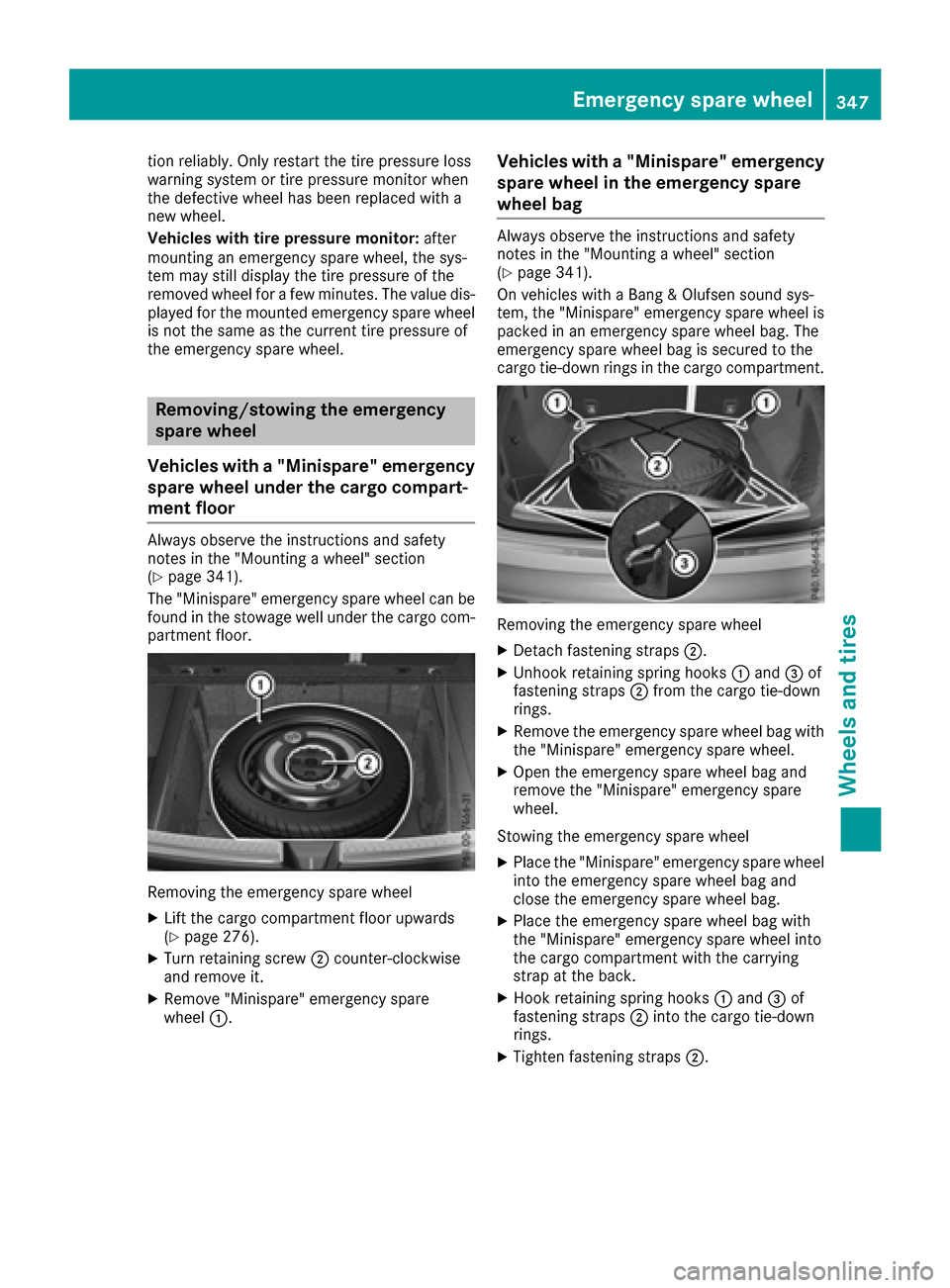
Removing the emergency spare wheel
XLift the cargo compartment floor upwards
(Ypage 276).
XTurn retaining screw ;counter-clockwise
and remove it.
XRemove "Minispare" emergency spare
wheel :.
Vehicles with a "Minispare" emergency
spare wheel in the emergency spare
wheel bag
Always observe the instructions and safety
notes in the "Mounting a wheel" section
(
Ypage 341).
On vehicles with a Bang & Olufsen sound sys-
tem, the "Minispare" emergency spare wheel is packed in an emergency spare wheel bag. The
emergency spare wheel bag is secured to the
cargo tie-down rings in the cargo compartment.
Removing the emergency spare wheel
XDetach fastening straps ;.
XUnhook retaining spring hooks :and =of
fastening straps ;from the cargo tie-down
rings.
XRemove the emergency spare wheel bag with
the "Minispare" emergency spare wheel.
XOpen the emergency spare wheel bag and
remove the "Minispare" emergency spare
wheel.
Stowing the emergency spare wheel
XPlace the "Minispare" emergency spare wheel
into the emergency spare wheel bag and
close the emergency spare wheel bag.
XPlace the emergency spare wheel bag with
the "Minispare" emergency spare wheel into
the cargo compartment with the carrying
strap at the back.
XHook retaining spring hooks :and =of
fastening straps ;into the cargo tie-down
rings.
XTighten fastening straps ;.
Emergency sparewheel347
Wheels an d tires
Z
Page 350 of 366
Mercedes-AMG vehicles with a collaps-
ible spare wheel under the cargo com-
partment floor
!Only place the collapsible spare wheel in the
vehicle when it is dry. Otherwise, moisture
may get into the vehicle.
Always observe the instructions and safety
notes in the "Mounting a wheel" section
(
Ypage 341).
The collapsible spare wheel can be found in the
stowage well under the cargo compartment
floor.
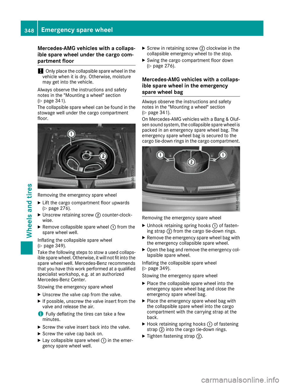
Removing the emergency spare wheel
XLift the cargo compartment floor upwards
(Ypage 276).
XUnscrew retaining screw ;counter-clock-
wise.
XRemove collapsible spare wheel :from the
spare wheel well.
Inflating the collapsible spare wheel
(
Ypage 349).
Take the following steps to stow a used collaps- ible spare wheel. Otherwise, it will not fit into the
spare wheel well. Mercedes-Benz recommends
that you have this work performed at a qualified
specialist workshop, e.g. at an authorized
Mercedes-Benz Center.
Stowing the emergency spare wheel
XUnscrew the valve cap from the valve.
XIf possible, unscrew the valve insert from the
valve and release the air.
iFully deflating the tires can take a few
minutes.
XScrew the valve insert back into the valve.
XScrew the valve cap back on.
XLay collapsible spare wheel :in the emer-
gency spare wheel well.
XScrew in retaining screw ;clockwise in the
collapsible emergency wheel to the stop.
XSwing the cargo compartment floor down
(Ypage 276).
Mercedes-AMG vehicles with a collaps-
ible spare wheel in the emergency
spare wheel bag
Always observe the instructions and safety
notes in the "Mounting a wheel" section
(
Ypage 341).
On Mercedes-AMG vehicles with a Bang & Oluf-
sen sound system, the collapsible spare wheel is packed in an emergency spare wheel bag. The
emergency spare wheel bag is secured to the
cargo tie-down rings in the cargo compartment.
Removing the emergency spare wheel
XUnhook retaining spring hooks :of fasten-
ing strap ;from the cargo tie-down rings.
XRemove the emergency spare wheel bag with
the emergency collapsible spare wheel.
XOpen the bag and remove the emergency col-
lapsible spare wheel.
Inflating the collapsible spare wheel
(
Ypage 349).
Stowing the emergency spare wheel
XPlace the collapsible spare wheel into the
emergency spare wheel bag and close the
emergency spare wheel bag.
XPlace the emergency spare wheel bag with
the collapsible spare wheel into the cargo
compartment with the carrying strap at the
back.
XHook retaining spring hooks :of fastening
strap ;into the cargo tie-down rings.
XTighten fastening strap ;.
348Emergency spare wheel
Wheels and tires
Page 351 of 366
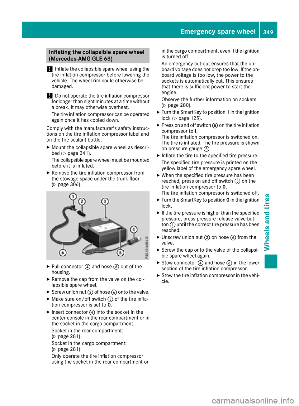
Inflating the collapsible spare wheel
(Mercedes-AMG GLE 63)
!
Inflat eth ecollapsible spar ewhee lusin gth e
tire inflation compressor before lowering th e
vehicle. The whee lrim could otherwise be
damaged.
!Do no toperate th etire inflation compressor
for longer than eigh tminute sat atime without
a break. It may otherwise overheat.
The tire inflation compressor can be operate d
again once it has cooled down .
Comply wit hth emanufacturer' ssafet yinstruc-
tion son th etire inflation compressor label and
on th etire sealan tbottle.
XMoun tth ecollapsible spar ewhee las descri-
bed (Ypage 341).
The collapsible spar ewhee lmust be mounte d
before it is inflated.
XRemove th etire inflation compressor from
th estowage spac eunder th etrunk floor
(
Ypage 306).
XPull connecto r? and hos eB out of th e
housing .
XRemove th ecap from th evalv eon th ecol-
lapsible spar ewheel.
XScrew unio nnut ;of hos eB onto th evalve.
XMak esur eon/off switch Aof th etire infla-
tion compressor is set to 0.
XInsertconnecto r? intoth esocke tin th e
center console in th erear compartmen tor in
th esocke tin th ecargo compartment.
Socket in th erear compartment:
(
Ypage 281)
Socket in th ecargo compartment:
(
Ypage 281)
Only operate th etire inflation compressor
usin gth esocke tin th erear compartmen tor in th
ecargo compartment, eve nif th eignition
is turne doff .
An emergenc ycut-out ensures that th eon -
boar dvoltag edoes no tdro pto olow. If th eon -
boar dvoltag eis to olow, th epower to th e
sockets is automatically cut .This ensures
that there is sufficien tpower to start th e
engine.
Observ eth efurther information on sockets
(
Ypage 280).
XTurn th eSmartKey to position 1in th eignition
loc k (Ypage 125).
XPress on and off switch Aon th etire inflation
compressor to I.
The tire inflation compressor is switched on .
The tire i
s inflated. The tire pressur eis shown
on pressur egauge =.
XInflateth etire to th especifie dtire pressure.
The specifie dtire pressur eis printe don th e
yellow label of th eemergenc yspar ewheel.
XWhen th especifie dtire pressur ehas been
reached, press on and off switch Aon th e
tire inflation compressor to 0.
The tire inflation compressor is switched off .
XTurn theSmartKey to position 0in th eignition
lock.
XIf th etire pressur eis higher than th especifie d
pressure, press pressur erelease valv ebut -
to n: until th ecorrec ttire pressur ehas been
reached.
XUnscrew unio nnut ;on hos eB from th e
valve.
XScrew th ecap onto th evalv eof th ecollapsi-
ble spar ewhee lagain .
XStow connecto r? and hos eB in th elower
section of th etire inflation compressor.
XStow th etire inflation compressor in th evehi-
cle .
Emergency spare wheel349
Wheels and tires
Z
Page 359 of 366
Comply with the important safety notes for ser-
vice products when handlin g coolant
(
Ypage 352).
The coolant isa mixture of water and ant i-
freeze/corrosion inh ibitor. It is responsible for
the foll owing:
RAnti-corrosion protection
RAntifreeze protection
RRaisin g the boiling point
If the coolant has antifreeze protection downto
-35 ‡ (-37 †), the boilingpoin t of the coolant
during operation is approximately 266 ‡
(130 †).
The antifreeze concentrate /corrosion inh ibitor
concentration inthe engine co oling system
should:
Rbe at least 50 %.This willprotect the engine
co olin g system against freezing downto
approximate ly-35 ‡ (-37 †).
Rnot exceed 55% (antifreeze protection down
to -49 ‡ [-45 †]). Otherwise, heat willnotbe
dissipat ed as effectively.
Mercedes-Benz recommends an antifreeze/
corrosion inh ibitor concentrate inaccordance
wit h MB Specifications for Service Products
310.1.
iWhen the veh icle isfirstdeliv ered, it is fille d
wit h a coolant mixture that ensures adequate
antifreeze and anti-corrosion protection.
iThe coolant ischecked with every mainte-
nance interval at a qualified specialist work-
shop.
Filling capacities
ModelCapacity
Mercedes ‑AMG
vehiclesApprox. 11.9 US qt
(11.3 l)
GLE350 d4MATIC
CoupeApprox. 12.2 US qt
(11.5 l)
All other models
Windshield washer system
Important safety notes
GWARNING
Windshield washer concentrate could ignite if
it comes into contact with hot engine compo-
nents or the exhaust system. There isa risk of
fire and injury.
Make sure that no windshield washer con-
centrate is spilled next to the filler neck.
!Only MB SummerFit and MB WinterF it
washer fluid should bemixed together. The
spray nozzles may otherwise become
blocked.
Do not use distilled or de-ionized water. Other-
wise, the level sensor may givea false reading.
When handling washer fluid, observe the impor-
tant safety notes on service products
(
Ypage 352).
At temperatures above freezing:
XFill the washer fluid reservoir with a mixture of
water and windshield washer fluid, e.g. MB
SummerFit.
Add 1 part MB SummerFit to 100 parts water.
At temperatures below freezing:
XFill the washer fluid reservoir with a mixture of
water and washer fluid, e.g. MB WinterFit.
For the correct mixing ratio refer to the infor-
mation on the antifreeze reservoir.
iAdd windshield washer fluid, e.g. MB Sum-
merFit or MB WinterFit, to the washer fluid all
year roun d.
Climate control system refrigerant
Important safety notes
The clim ate control system of your vehicle is fil-
led with refrigerant R‑ 134a.
The instruction label regarding the refrigerant
type used can be found on the radiator cross
member.
!Only the refrigerant R‑134a and the PAG oil
approved by Mercedes-Benz may be used.
The appr oved PAG oil may not be mixed with
any other PAG oil that is not approved for
Service products and filling capacities357
Technical data
Z