2017 MERCEDES-BENZ GLC COUPE tow
[x] Cancel search: towPage 202 of 370

XSwitch off the engine.
XClose the doors and tailgate.
XCouple up the trailer.
XEstablish the electrical connection between
the vehicle and the trailer.
XCheck that the trailer lighting system is work-
ing.
XPush the combination switch upwards/down-wards and check whether the corresponding
turn signal on the trailer flashes.
A trailer that is connected is recognized only
when the electrical connection is established
correctly and when the lighting system is work-
ing properly. The function of other systems also
depends on this, for example:
RESP®
RPARKTRONIC
RActive Parking Assist
RActive Blind Spot Assist
RActive Lane Keeping Assist
Vehicles with AIR BODY CONTROL: if you couple
up a trailer, the vehicle always remains at high-
way level. Observe the following note when cou-
pling up a trailer:
RUnless highway level has been set manually,
the vehicle is automatically lowered to high-
way level. If a speed of 5 mph (8 km/h) has
been reached, this may be the case.
These restrictions apply to accessories that are
supplied with power via the trailer socket in your
vehicle, e.g. a rear bicycle rack.
Observe the maximum permissible trailer
dimensions (width and length).
Most U.S. states and all Canadian provinces
require by law:
RSafety chains between the towing vehicle and
the trailer. The chains should be cross-wound
under the trailer drawbar. They must be fas-
tened to the vehicle's trailer coupling, not to
the bumper or the axle.
Leave enough play in the chains to make tight
cornering possible.
RA separate brake system for certain types of
trailer.
RSafety switch for braked trailers. Check the
specific legal requirements applicable to your state.
If the trailer becomes detached from the tow-
ing vehicle, the safety feature applies the
trailer brakes.
Towing a trailer
There are several legal requirements for towing
a trailer, e.g. the maximum permissible speed.
Make sure that your car/trailer combination
complies with the local regulations:
Rin your place of residence
Rat your destination
The police and local authorities can provide reli- able information.
To accumulate driving experience and accustom
yourself to the new handling characteristics,
practice the following at a location where there
is no traffic:
RCornering
RStopping
RBacking up
Check the following before the journey:
RTrailer tow hitch
RSafety switch for braked trailers
RSafety chains
RElectrical connections
RLighting system
RWheels and tires
RLoad securing
Adjust the exterior mirrors so that you have a
clear view of the rear section of the trailer.
If the trailer is equipped with electronically con-
trolled brakes, pull away carefully in the car/
trailer combination. Brake manually using the
brake controller and check whether the brakes
function correctly.
Regularly check that the load is secure.
When towing a trailer, your vehicle's handling
characteristics will be different in comparison
with when driving without a trailer.
The vehicle/trailer combination:
Ris heavier
Ris restricted in its acceleration and gradient-
climbing capability
Rhas an increased braking distance
Ris affected more by strong crosswinds
Rdemands more sensitive steering
Rhas a larger turning circle
Avoid sudden steering movements.
Avoid braking abruptly. If possible, brake gently
at first to allow the trailer to run on. Then,
increase the braking force rapidly.
200Towing a trailer
Driving and parking
Page 203 of 370

When overtaking, pay particular attention to the
extended length of your vehicle/trailer combi-
nation.
Due to the length of the vehicle/trailer combi-
nation, you require additional road space when
overtaking before you can change back to the
original lane.
If the automatic transmission repeatedly shifts
between gears on uphill or downhill gradients,
shift to a lower gear.
Driving in a lower gear and at a reduced speed
decreases the risk of engine damage.
If the coolant temperature increases signifi-
cantly when climate control is switched on,
switch climate control off.
Coolant heat can also be dissipated by opening
the windows and switching the ventilation
blower and the interior temperature to the high-
est level.
Decoupling a trailer
GWARNING
If you uncouple a trailer with the overrun
brake engaged, you could trap your hand
between the vehicle and the trailer drawbar.
There is a risk of injury.
Do not uncouple a trailer if the overrun brake
is engaged.
GWARNING
Vehicles with level control:
The vehicle is lowered as soon as you discon-
nect the trailer cable. This could result in your
limbs or those of other people that are
between the vehicle body and tires or under-
neath the vehicle being trapped. There is a
risk of injury.
Make sure that nobody is in the immediate
vicinity of the wheel housings or under the
vehicle when you disconnect the trailer cable.
!Do not disconnect a trailer with an engaged
overrun brake. Otherwise, your vehicle could
be damaged by the rebounding of the overrun
brake.
XApply the vehicle's parking brake manually.
XShift the transmission to position j.
XClose all doors and the tailgate.
XSwitch off the engine.
XSecure the vehicle and trailer against rolling
away.
XRemove the trailer cable.
XRemove the safety chains, if there are any.
XUncouple the trailer.
Removing the ball coupling
XObserve the manufacturer's installation
instructions.
XPress the protective cap into the ball coupling
recess.
XMake sure that the protective cap is firmly in
place.
Observe the loading guidelines (
Ypage 273)
and the safety notes regarding stowage spaces
(
Ypage 273).
Information on cleaning and care of the trailer
tow hitch (
Ypage 310).
Trailer power supply
!
Accessories with a maximum power con-
sumption of 180 W can be connected to the
permanent power supply.
You must not charge a trailer battery using the
power supply.
The trailer socket of your vehicle is equipped at
the factory with a permanent power supply.
The permanent power supply is supplied via
trailer socket pin 4.
The trailer's permanent power supply is
switched off in the event of low vehicle supply
voltage and after six hours at the latest.
A qualified specialist workshop can provide
more information about installing the trailer
electrics.
Permissible trailer loads and trailer
drawbar noseweights
Weight specifications
The gross trailer weight is calculated as the
weight of the trailer plus the weight of the load
and the trailer's equipment.
Towing a trailer201
Driving and parking
Z
Page 204 of 370

You will find permissible trailer loads under
"Technical data" (Ypage 365).
Loading a trailer
RWhen loading the trailer, make sure that nei-
ther the permissible gross trailer weight nor
the permissible gross vehicle weight are
exceeded. The permissible gross vehicle
weight is indicated on the identification plate
on the B-pillar on the driver's side of the vehi-
cle.
You can find the maximum permissible valueson the type plates of your vehicle and the
trailer. When calculating how much weight
the vehicle and trailer may carry, pay atten-
tion to the respective lowest values.
RThe trailer drawbar load on the ball coupling
must be added to the rear axle load to avoid
exceeding the permissible gross axle weight.
The permissible gross vehicle weight is indi-
cated on the identification plate on the B-pil-
lar on the driver's side of the vehicle.
Mercedes-Benz recommends a trailer load
where the trailer drawbar noseweight accounts
for 8% to 15% of the permissible gross trailer
weight.
Additional accessories, passengers and load
reduce the permissible trailer load and nose-
weight that your vehicle can tow.
Checking the vehicle and trailer weight
RHave the towing vehicle, including the driver,
passengers and load, and completely loaded
trailer weighed on a suitable weighing
machine. This will allow you to ensure that the
weights of the towing vehicle and trailer com-
ply with the maximum permissible values.
RCheck the gross axle weight rating of the front
and rear axles, the gross weight of the trailer
and trailer drawbar load.
202Towing a trailer
Driving and parking
Page 212 of 370

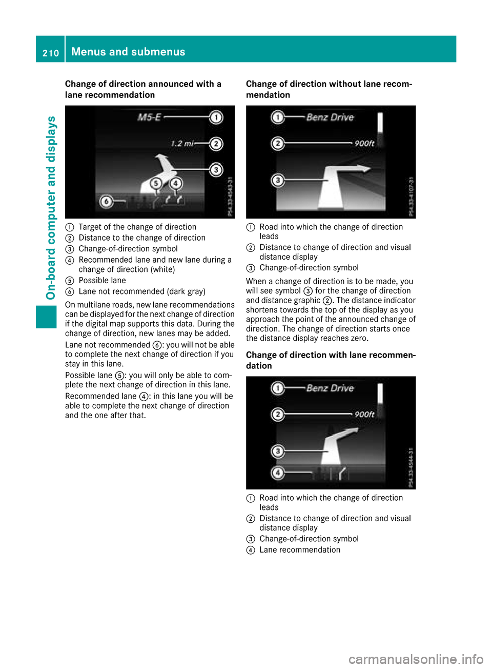
Change of direction announced with a
lane recommendation
:Target of the change of direction
;Distance to the change of direction
=Change-of-direction symbol
?Recommended lane and new lane during a
change of direction (white)
APossible lane
BLane not recommended (dark gray)
On multilane roads, new lane recommendations can be displayed for the next change of direction
if the digital map supports this data. During the
change of direction, new lanes may be added.
Lane not recommended B: you will not be able
to complete the next change of direction if you
stay in this lane.
Possible lane A: you will only be able to com-
plete the next change of direction in this lane.
Recommended lane ?: in this lane you will be
able to complete the next change of direction
and the one after that.
Change of direction without lane recom-
mendation
:Road into which the change of direction
leads
;Distance to change of direction and visual
distance display
=Change-of-direction symbol
When a change of direction is to be made, you
will see symbol =for the change of direction
and distance graphic ;. The distance indicator
shortens towards the top of the display as you
approach the point of the announced change of
direction. The change of direction starts once
the distance display reaches zero.
Change of direction with lane recommen-
dation
:Road into which the change of direction
leads
;Distance to change of direction and visual
distance display
=Change-of-direction symbol
?Lane recommendation
210Menus and submenus
On-board computer and displays
Page 228 of 370

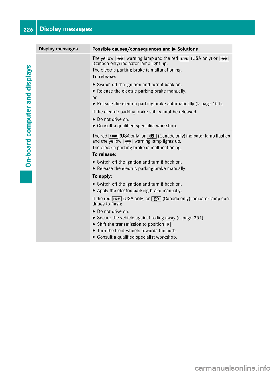
Display messagesPossible causes/consequences andMSolutions
The yellow!warning lamp and th ered F (USAonly) or !
(Canada only) indicator lamp ligh tup.
The electric parking brak eis malfunctioning .
To release:
XSwitc hoff th eignition and tur nit bac kon .
XReleas eth eelectric parking brak emanually.
or
XReleas eth eelectric parking brak eautomatically (Ypage 151).
If th eelectric parking brak estill canno tbe released:
XDo no tdrive on .
XConsult aqualified specialist workshop .
The redF(USAonly) or !(Canada only) indicator lamp flashes
and th eyellow !warning lamp lights up.
The electric parking brak eis malfunctioning .
To release:
XSwitc hoff th eignition and tur nit bac kon .
XReleas eth eelectric parking brak emanually.
To apply :
XSwitchoff th eignition and tur nit bac kon .
XApply th eelectric parking brak emanually.
If th ered F (USAonly) or !(Canada only) indicator lamp con-
tinue sto flash:
XDo no tdrive on .
XSecureth evehicl eagainst rollin gaway (Ypage 351).
XShift th etransmission to position j.
XTurn thefron twheels toward sth ecurb.
XConsult aqualified specialist workshop .
226Display messages
On-board computer and displays
Page 242 of 370

Display messagesPossible causes/consequences andMSolutions
Á
Drive MoreSlowly
You canno tchang eth evehicl elevel. Possibl ecauses are:
RYou are drivin gto ofas tfor th eselected vehicl elevel
RYou are drivin gto ofas twit h a trailer or th etrailer-coupling socke tis
bein gused ,e.g. for abicycle rac k
XDrive moreslowly and then select th edesire dvehicl elevel again
(Ypage 168).
XObserv eth enote son towin g atrailer (Ypage 198).
Á
Compresso rIs Cool‐ing
You hav eselected ahigher vehicl elevel. The compressor first needs
to cool down because of frequen tlevel changes.
XDrive in amanne rappropriat efor th ecurren tvehicl elevel.
XMak esur ethat there is sufficien tground clearance .
XAllow thecompressor to cool down .
Whe nth ecompressor has cooled down ,th edisplay message dis-
appears. The vehicl ethen continues rising to th eselected level.
Á
Malfunction
AI R BODY CONTROL is malfunctioning .The vehicle's handlin gchar-
acteristics may be affected.
Mercedes-AMG vehicles: theAM Gsport ssuspension base don AI R
BODY CONTROL is malfunctioning .The vehicle's handlin gcharacter-
istics may be affected.
XDrive as appropriat efor th ecurren tvehicl elevel, but do no texceed
50 mph (80 km/h).
XMak esur ethat there is sufficien tground clearance .
XVisitaqualified specialist workshop .
LaneKeepin gAssistCurrently Unavaila‐ble See Operator' sManualorActiveLan eKeepin gAssistCurrently Unavaila‐ble See Operator' sManual
LaneKeepin gAssis tor Active Lan eKeepin gAssis tis deactivated and
temporarily inoperative.
Possibl ecauses are:
RThe windshield in th ecamera' sfield of vision is dirty.
RVisibilit yis impaire ddue to heav yrain ,snow or fog .
RThere havebeen no lan emarking sfor an extended period.
RThe lan emarking sare worn, dark or covered, e.g. by dir tor snow.
Whe nth ecauses state dabov eno longer apply, th edisplay message
disappears.
Lan eKeepin gAssis tor Active Lan eKeepin gAssis tis operational
again .
If th edisplay message does no tdisappear :
XPull overand stop th evehicl esafely as soo nas possible, payin g
attention to roa dand traffic conditions.
XSecur eth evehicl eagainst rollin gaway (Ypage 149).
XClean th ewindshield.
Lan eKeepin gAssistInoperativeor
ActiveLan eKeepin gAssist Inoperative
LaneKeepin gAssis tor Active Lan eKeepin gAssis tis malfunctioning .
XVisitaqualified specialist workshop .
240Display messages
On-board computer and displays
Page 254 of 370

Warning/
indicator
lampNSignal type
Possible causes/consequences and M
Solutions
üNThe red seat belt warning lamp lights up after the engine starts, as soon as the
driver's or the front-passenger door is closed.
The driver or front passenger has not fastened their seat belt.
XFasten your seat belt (Ypage 46).
The warning lamp goes out.
There are objects on the front-passenger seat.
XRemove the objects from the front-passenger seat and stow them in a secure
place.
The warning lamp goes out.
üN The red seat belt warning lamp flashes and an intermittent audible warning
sounds.
The driver or front passenger has not fastened their seat belt. The vehicle is being driven faster than 15 mph (25 km/h) or has briefly been driven faster than 15 mph
(25 km/h).
XFasten your seat belt (Ypage 46).
The warning lamp goes out and the intermittent warning tone ceases.
There are objects on the front-passenger seat. The vehicle is being driven faster
than 15 mph (25 km/h) or has briefly been driven faster than 15 mph (25 km/h).
XRemove the objects from the front-passenger seat and stow them in a secure
place.
The warning lamp goes out and the intermittent warning tone ceases.
252Warning and indicator lamps in the instrument cluster
On-board computer and displays
Page 274 of 370

Inserting an SD card
TheSDcard slot islocated inthe stowage com-
partment under the armrest.
XIn sert the SDcard into the SDcard slot unt il
the SDcard engages. The side with the con-
tacts must face down.
XSelect the med iasource (Ypage 271).
Removing an SD card
XPress the SDcard.
The SDcard isejected.
XRemove the memory car d.
Connecting USB devices
There are two USB ports inthe stowage space
under the armrest.
XConnect the USB device to the USB port.
XSelect the med iasource (Ypage 271).
272Operating system
Multimedia system