2017 MERCEDES-BENZ GLA SUV phone
[x] Cancel search: phonePage 293 of 369
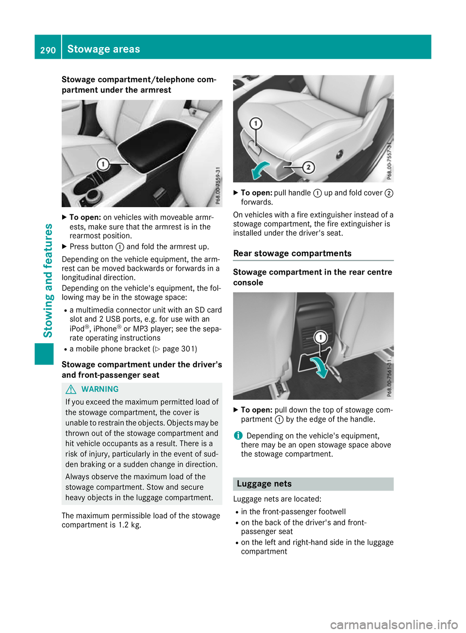
Stowage compartment/telephone com-
partment under the armrest X
To open: on vehicles with moveable armr-
ests, make sure that the armrest is in the
rearmost position.
X Press button :and fold the armrest up.
Depending on the vehicle equipment, the arm-
rest can be moved backwards or forwards in a
longitudinal direction.
Depending on the vehicle's equipment, the fol-
lowing may be in the stowage space:
R a multimedia connector unit with an SD card
slot and 2 USB ports, e.g. for use with an
iPod ®
, iPhone ®
or MP3 player; see the sepa-
rate operating instructions
R a mobile phone bracket (Y page 301)
Stowage compartment under the driver's and front-passenger seat G
WARNING
If you exceed the maximum permitted load of the stowage compartment, the cover is
unable to restrain the objects. Objects may be
thrown out of the stowage compartment and
hit vehicle occupants as a result. There is a
risk of injury, particularly in the event of sud-
den braking or a sudden change in direction.
Always observe the maximum load of the
stowage compartment. Stow and secure
heavy objects in the luggage compartment.
The maximum permissible load of the stowage
compartment is 1.2 kg. X
To open: pull handle :up and fold cover ;
forwards.
On vehicles with a fire extinguisher instead of a
stowage compartment, the fire extinguisher is
installed under the driver's seat.
Rear stowage compartments Stowage compartment in the rear centre
console
X
To open: pull down the top of stowage com-
partment :by the edge of the handle.
i Depending on the vehicle's equipment,
there may be an open stowage space above
the stowage compartment. Luggage nets
Luggage nets are located:
R in the front-passenger footwell
R on the back of the driver's and front-
passenger seat
R on the left and right-hand side in the luggage
compartment 290
Stowage areasStowing and features
Page 299 of 369
Roof carrier
Important safety notes G
WARNING
When a load is transported on the roof, the
vehicle's centre of gravity rises and the han-
dling changes. If you exceed the maximum
roof load, the handling as well as steering and braking characteristics are severely affected.
There is a risk of an accident.
Always observe the maximum roof load and
adapt your driving style.
! Mercedes-Benz recommends that you only
use roof carriers that have been tested and
approved for Mercedes-Benz vehicles. This
helps to prevent damage to the vehicle.
Position the load on the roof carrier in such a way that the vehicle will not sustain damage
even when it is in motion.
Ensure that, depending on the vehicle's
equipment, you can raise the panorama slid-
ing sunroof fully and open the tailgate fully
when the roof carrier is fitted.
You will find information on the maximum roof
load in the "Technical data" section
(Y page 358).
An incorrectly secured roof carrier or roof load
may become detached from the vehicle. You
must therefore ensure that you observe the roof
carrier manufacturer's installation instructions.
Attaching the roof carrier X
Secure the roof carrier to the roof rails. In
doing so, observe the manufacturer's instal-
lation instructions. Features
Cup holders
Important safety notes G
WARNING
The cup holder cannot secure a drinks con-
tainer in place during a journey. If you use a
cup holder during a journey, the drinks con- tainer could be flung around and liquid could
be spilt. Vehicle occupants could come into
contact with the liquid and, in particular, be
scalded by hot liquid. You could be distracted
from the traffic situation and lose control of
the vehicle. There is a risk of an accident and
injury.
Only use the cup holder when the vehicle is
stationary. Only place containers of a suitable size in the cup holder. Seal the container, in
particular when it contains hot liquid. G
WARNING
If you transport objects in the vehicle interior and these are not adequately secured, they
could slip or be flung around and thereby
strike vehicle occupants. In addition, cup
holders, open stowage spaces and mobile
phone brackets may not always be able to
hold the objects placed in them in the event of an accident. There is a risk of injury, particu-
larly in the event of sharp braking or sudden
changes of direction.
R Always stow objects in such a way that they
cannot be tossed about in these or similar
situations.
R Always make sure that objects do not proj-
ect from stowage spaces, luggage nets or
stowage nets.
R Ensure that closable stowage spaces are
shut before beginning your journey.
R Always stow and secure heavy, hard, poin-
ted, sharp-edged, fragile or outsize objects
in the load compartment.
! Only use the cup holders for containers of
the right size and which have lids. The drinks
could otherwise spill.
Observe the loading guidelines (Y page 288).
The stowage compartments in the doors provide
space for bottles:
R front: capacity up to 1.0 l
R rear: capacity up to 0.5 l 296
FeaturesStowing and features
Page 302 of 369
X
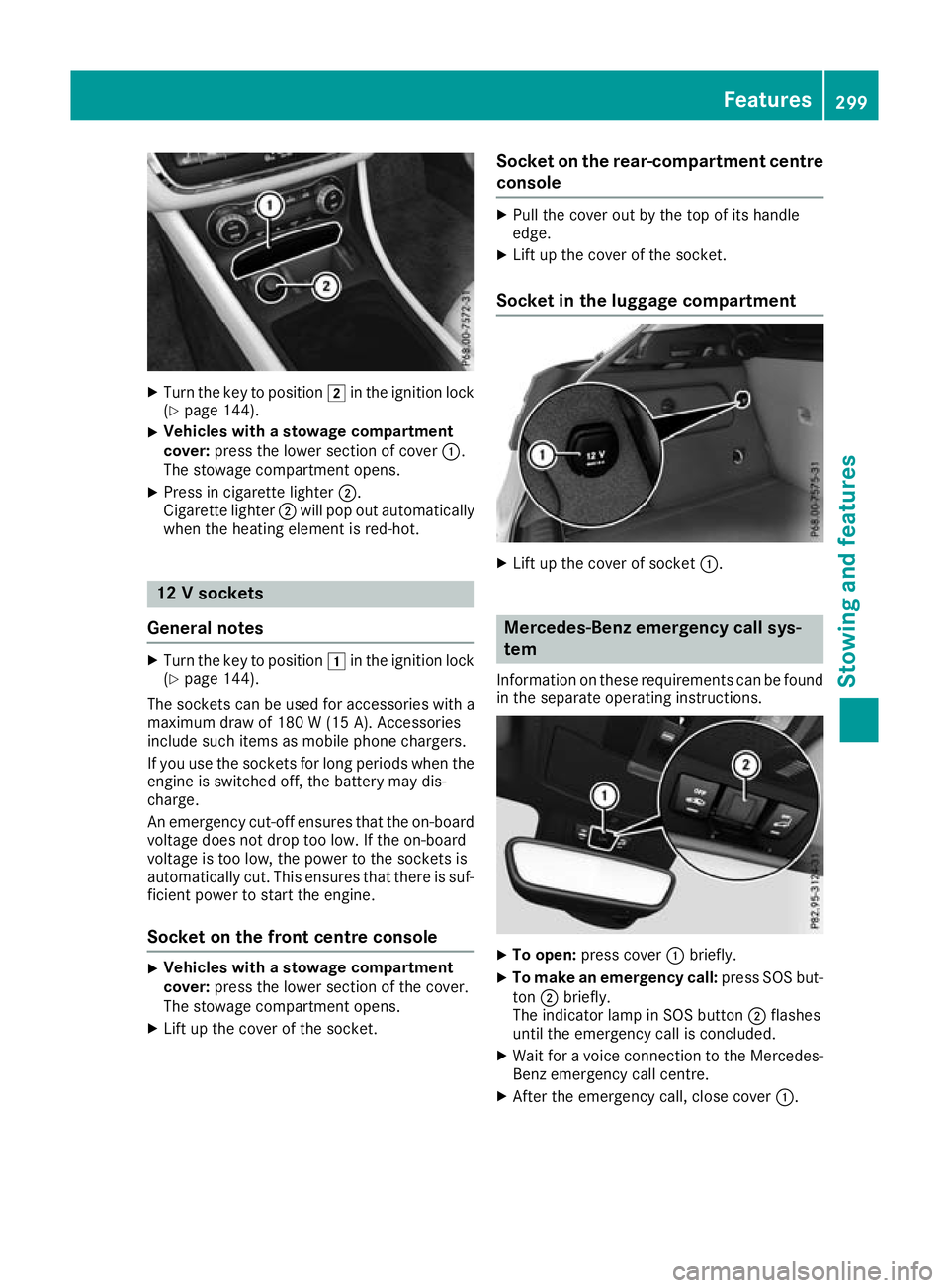
Turn the key to position 2in the ignition lock
(Y page 144).
X Vehicles with a stowage compartment
cover: press the lower section of cover :.
The stowage compartment opens.
X Press in cigarette lighter ;.
Cigarette lighter ;will pop out automatically
when the heating element is red-hot. 12 V sockets
General notes X
Turn the key to position 1in the ignition lock
(Y page 144).
The sockets can be used for accessories with a
maximum draw of 180 W (15 A). Accessories
include such items as mobile phone chargers.
If you use the sockets for long periods when the engine is switched off, the battery may dis-
charge.
An emergency cut-off ensures that the on-board
voltage does not drop too low. If the on-board
voltage is too low, the power to the sockets is
automatically cut. This ensures that there is suf- ficient power to start the engine.
Socket on the front centre console X
Vehicles with a stowage compartment
cover:
press the lower section of the cover.
The stowage compartment opens.
X Lift up the cover of the socket. Socket on the rear-compartment centre
console X
Pull the cover out by the top of its handle
edge.
X Lift up the cover of the socket.
Socket in the luggage compartment X
Lift up the cover of socket :. Mercedes-Benz emergency call sys-
tem
Information on these requirements can be found in the separate operating instructions. X
To open: press cover :briefly.
X To make an emergency call: press SOS but-
ton ;briefly.
The indicator lamp in SOS button ;flashes
until the emergency call is concluded.
X Wait for a voice connection to the Mercedes-
Benz emergency call centre.
X After the emergency call, close cover :. Features
299Stowing and features Z
Page 303 of 369
You will see a message if:
R a connection to the Mercedes-Benz emer-
gency call centre cannot be made
R a call has not been automatically forwarded
to the public emergency call centre
In this case, dial the 112emergency number
on your mobile phone.
You can find more information on the Mercedes-
Benz emergency call system in the separate
operating instructions. Mobile phone
Important safety notes G
WARNING
If you operate mobile communication equip-
ment while driving, you can be distracted from the traffic situation. This could also cause you
to lose control of the vehicle. There is a risk of an accident.
Only operate this equipment when the vehicleis stationary.
You must observe the legal requirements for the country in which you are currently driving whenoperating mobile communications equipment in
the vehicle.
If it is permitted by law to operate communica-
tions equipment while the vehicle is in motion,
you may do so only if the traffic situation per-
mits. You may otherwise be distracted from the traffic conditions, cause an accident and injure
yourself and others.
Excessive levels of electromagnetic radiation
may cause damage to your health and to the
health of others. The use of an exterior aerial
takes into consideration the scientific discus-
sion surrounding the possible health risk posed
by electromagnetic fields.
Mercedes-Benz recommends the use of an
approved exterior aerial. This ensures:
R optimal mobile phone reception quality in the
vehicle
R that mutual interference between the vehicle
electronics and mobile phones is minimised An exterior aerial has the following advantages:
R it conducts the electromagnetic fields gener-
ated by a wireless device to the exterior
R the field strength in the vehicle interior is
lower than in a vehicle that does not have an exterior aerial
Information on retrofitting two-way radios and
mobile phones (RF transmitters) (Y page 350).
General notes There are various mobile phone brackets that
may be fitted in your vehicle; in some cases,
these are country-specific.
You can connect a Bluetooth
®
-capable mobile
phone with the multimedia system via the Blue-
tooth ®
interface. This also applies if your vehicle
is equipped with convenience telephony.
More information on suitable mobile phones,
mobile phone brackets and on connecting Blue-
tooth ®
-capable mobile phones with the multi-
media system can be obtained:
R at your Mercedes-Benz Service Centre
R on the Internet at http://www.mercedes-
benz.com/connect
The functions and services available when you
use the phone depend on your mobile phone
model and service provider.
Using a mobile phone To connect a mobile phone to the exterior aerial
and charge it, insert it into the mobile phone
bracket.
X Open the telephone compartment
(Y page 290).
X Place the mobile phone bracket into the pre-
installed fitting; see the separate installation
instructions for the mobile phone fitting.
X Insert the mobile phone into the mobile phone
bracket; see the separate installation instruc-
tions for the mobile phone fitting.
i The mobile phone can also be operated
without being in the bracket. However, the
charging function and aerial function are not
available.
In order to use Bluetooth ®
(SAP profile) on your
telephone module, you must first insert the tele-
phone module into the pre-installed fitting. This connects it to the exterior aerial. If you wish to 300
FeaturesStowing and features
Page 304 of 369
charge the mobile phone, you must connect it to
a USB port.
Further information on the telephone module
with Bluetooth ®
(SAP profile) can be found in the
Digital Owner's Manual.
Operating the mobile phone You can operate the phone using the
6and
~ buttons on the multifunction steering
wheel. You can operate other mobile phone
functions via the on-board computer
(Y page 225).
When you remove the key from the ignition lock, the mobile phone is disconnected from the vehi-cle. You can then no longer make calls using the
hands-free system.
If a call is active and you remove the key from
the ignition lock, the conversation is transferred
over to the mobile phone. It is then possible to
continue the conversation on the mobile phone.
Mobile phone bracket in the stowage
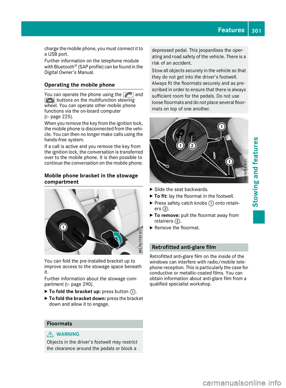
compartment You can fold the pre-installed bracket up to
improve access to the stowage space beneath
it.
Further information about the stowage com-
partment (Y
page 290).
X To fold the bracket up: press button:.
X To fold the bracket down: press the bracket
down and allow it to engage. Floormats
G
WARNING
Objects in the driver's footwell may restrict
the clearance around the pedals or block a depressed pedal. This jeopardises the oper-
ating and road safety of the vehicle. There is a
risk of an accident.
Stow all objects securely in the vehicle so that
they do not get into the driver's footwell.
Always fit the floormats securely and as pre-
scribed in order to ensure that there is always sufficient room for the pedals. Do not use
loose floormats and do not place several floor-mats on top of one another. X
Slide the seat backwards.
X To fit: lay the floormat in the footwell.
X Press safety catch knobs :onto retain-
ers ;.
X To remove: pull the floormat away from
retainers ;.
X Remove the floormat. Retrofitted anti-glare film
Retrofitted anti-glare film on the inside of the
windows can interfere with radio/mobile tele-
phone reception. This is particularly the case for conductive or metallic-coated films. You can
obtain information about anti-glare film from a
qualified specialist workshop. Features
301Stowing and features Z
Page 308 of 369
Topping up engine oil
G
WARNING
Certain components in the engine compart-
ment could be very hot, e.g. the engine, the
radiator and parts of the exhaust system.
There is a risk of injury when accessing the
engine compartment.
As far as possible, allow the engine to cool
down and only touch the components descri- bed in the following. G
WARNING
If engine oil comes into contact with hot com- ponents in the engine compartment, it may
ignite. There is a risk of fire and injury.
Make sure that engine oil does not spill out
over the filler neck. Allow the engine to cool
down and thoroughly clean the components
that have come into contact with engine oil
before you start the engine. H
Environmental note
When topping up the oil, take care not to spill
any. If oil enters the soil or waterways, it is
harmful to the environment.
! Use only engine oils and oil filters that are
approved for vehicles with a service system. A
list of the engine oils and oil filters that have
been tested and approved in accordance with Mercedes-Benz Specifications for Service
Products is available at any Mercedes-Benz
Service Centre.
The following cause engine failure or damage
to the exhaust system:
R Use of engine oils and oil filters that have
not been expressly approved for the service system
R Replacement of engine oil and oil filter after
the replacement interval specified by the
service system has expired
R Use of engine oil additives
! Do not add too much oil. Topping up with too
much engine oil can result in damage to the
engine or to the catalytic converter. Have
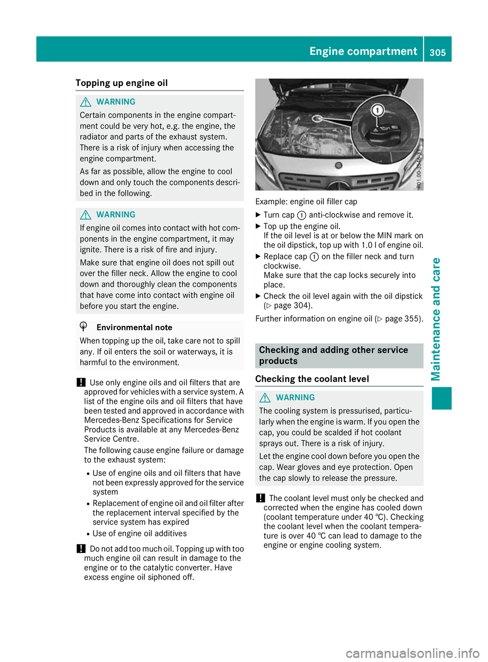
excess engine oil siphoned off. Example: engine oil filler cap
X Turn cap :anti-clockwise and remove it.
X Top up the engine oil.
If the oil level is at or below the MIN mark on
the oil dipstick, top up with 1.0 lof engine oil.
X Replace cap :on the filler neck and turn
clockwise.
Make sure that the cap locks securely into
place.
X Check the oil level again with the oil dipstick
(Y page 304).
Further information on engine oil (Y page 355). Checking and adding other service
products
Checking the coolant level G
WARNING
The cooling system is pressurised, particu-
larly when the engine is warm. If you open the cap, you could be scalded if hot coolant
sprays out. There is a risk of injury.
Let the engine cool down before you open the
cap. Wear gloves and eye protection. Open
the cap slowly to release the pressure.
! The coolant level must only be checked and
corrected when the engine has cooled down
(coolant temperature under 40 †). Checking
the coolant level when the coolant tempera-
ture is over 40 † can lead to damage to the
engine or engine cooling system. Engine compartment
305Maintenance and care Z
Page 324 of 369
Tyre pressure not reached
If a pressure of 180 kPa (1.8 bar/26 psi) has not
been attained after five minutes:
X Switch off the tyre inflation compressor.
X Unscrew the filler hose from the valve of the
faulty tyre.
Please note that tyre sealant may leak out
when unscrewing the filler hose.
X Very slowly drive the vehicle forwards or
reverse approximately 10 m.
X Pump up the tyre again.
After a maximum of five minutes the tyre
pressure must be at least 180 kPa (1.8 bar/
26 psi). G
WARNING
If the required tyre pressure is not reached
after the specified time, the tyre is too badly
damaged. The tyre sealant cannot repair the
tyre in this instance. Damaged tyres and a tyre pressure that is too low can significantly
impair the vehicle's braking and driving char-
acteristics. There is a risk of accident.
Do not continue driving. Contact a qualified
specialist workshop.
Tyre pressure reached G
WARNING
A tyre temporarily sealed with tyre sealant
impairs the driving characteristics and is not
suitable for higher speeds. There is a risk of
accident.
You should therefore adapt your driving style
accordingly and drive carefully. Do not exceed the specified maximum speed with a tyre that
has been repaired using tyre sealant.
The maximum permissible speed for a tyre
sealed with tyre sealant is 80 km/h. The upper
part of the TIREFIT sticker must be affixed to the
instrument cluster where it will be easily seen by
the driver. If a tyre pressure of 180 kPa (1.8 bar/26 psi) has
been reached after five minutes:
X Switch off the tyre inflation compressor.
X Unscrew the filler hose from the valve of the
faulty tyre.
Please note that tyre sealant may leak out
when unscrewing the filler hose.
X Stow the tyre sealant bottle, the tyre inflation
compressor and the warning triangle.
X Pull away immediately.
X Stop after driving for approximately ten
minutes and check the tyre pressure with the
tyre inflation compressor.
The tyre pressure must now be at least
130 kPa (1.3 ba r/19 psi). G
WA
RNING
If the required tyre pressure is not reached
after driving for a short period, the tyre is too badly damaged. The tyre sealant cannot
repair the tyre in this instance. Damaged tyres and a tyre pressure that is too low can signif-
icantly impair the vehicle's braking and driv-
ing characteristics. There is a risk of accident.
Do not continue driving. Contact a qualified
specialist workshop.
i In your vehicle, you will find a sticker with
the Mercedes-Benz Service24h telephone
number, e.g. on the B-pillar on the driver's
side.
X Correct the tyre pressure if it is still at least
130 kPa (1.3 ba r/19 psi). See the tyre pres-
sure table on the fuel filler flap for values.
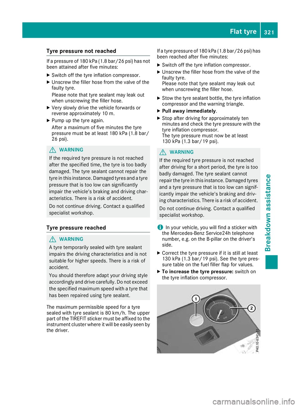
X To increase the tyre pressure: switch on
the tyre inflation compressor. Flat tyre
321Breakdown assistance Z
Page 343 of 369
Tyre pressure monitor
General notes If a tyre pressure monitor is fitted, the vehicle's
wheels have sensors fitted that monitor the tyre
pressures in all four tyres. The tyre pressure
monitor warns you if the pressure drops in one
or more of the tyres. The tyre pressure monitor
functions only if the corresponding sensors are
fitted to all wheels.
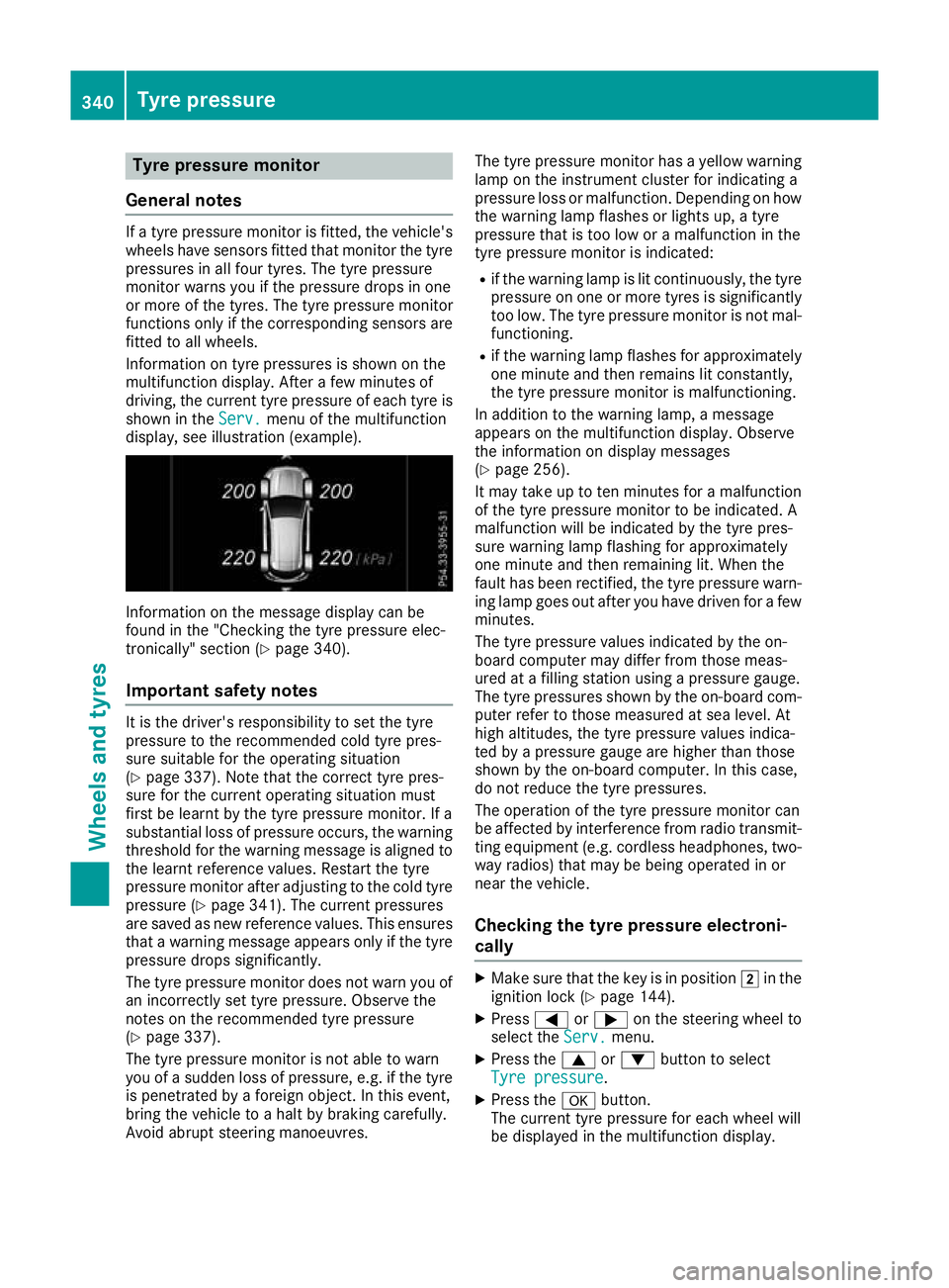
Information on tyre pressures is shown on the
multifunction display. After a few minutes of
driving, the current tyre pressure of each tyre is
shown in the Serv.
Serv. menu of the multifunction
display, see illustration (example). Information on the message display can be
found in the "Checking the tyre pressure elec-
tronically" section (Y page 340).
Important safety notes It is the driver's responsibility to set the tyre
pressure to the recommended cold tyre pres-
sure suitable for the operating situation
(Y page 337). Note that the correct tyre pres-
sure for the current operating situation must
first be learnt by the tyre pressure monitor. If a
substantial loss of pressure occurs, the warning threshold for the warning message is aligned to
the learnt reference values. Restart the tyre
pressure monitor after adjusting to the cold tyre pressure (Y page 341). The current pressures
are saved as new reference values. This ensures that a warning message appears only if the tyre
pressure drops significantly.
The tyre pressure monitor does not warn you of
an incorrectly set tyre pressure. Observe the
notes on the recommended tyre pressure
(Y page 337).
The tyre pressure monitor is not able to warn
you of a sudden loss of pressure, e.g. if the tyre is penetrated by a foreign object. In this event,
bring the vehicle to a halt by braking carefully.
Avoid abrupt steering manoeuvres. The tyre pressure monitor has a yellow warning
lamp on the instrument cluster for indicating a
pressure loss or malfunction. Depending on how
the warning lamp flashes or lights up, a tyre
pressure that is too low or a malfunction in the
tyre pressure monitor is indicated:
R if the warning lamp is lit continuously, the tyre
pressure on one or more tyres is significantly too low. The tyre pressure monitor is not mal-
functioning.
R if the warning lamp flashes for approximately
one minute and then remains lit constantly,
the tyre pressure monitor is malfunctioning.
In addition to the warning lamp, a message
appears on the multifunction display. Observe
the information on display messages
(Y page 256).
It may take up to ten minutes for a malfunction
of the tyre pressure monitor to be indicated. A
malfunction will be indicated by the tyre pres-
sure warning lamp flashing for approximately
one minute and then remaining lit. When the
fault has been rectified, the tyre pressure warn- ing lamp goes out after you have driven for a few minutes.
The tyre pressure values indicated by the on-
board computer may differ from those meas-
ured at a filling station using a pressure gauge.
The tyre pressures shown by the on-board com-
puter refer to those measured at sea level. At
high altitudes, the tyre pressure values indica-
ted by a pressure gauge are higher than those
shown by the on-board computer. In this case,
do not reduce the tyre pressures.
The operation of the tyre pressure monitor can
be affected by interference from radio transmit- ting equipment (e.g. cordless headphones, two-way radios) that may be being operated in or
near the vehicle.
Checking the tyre pressure electroni-
cally X
Make sure that the key is in position 2in the
ignition lock (Y page 144).
X Press =or; on the steering wheel to
select the Serv. Serv.menu.
X Press the 9or: button to select
Tyre pressure
Tyre pressure.
X Press the abutton.
The current tyre pressure for each wheel will
be displayed in the multifunction display. 340
Tyre pressureWheels and tyres