2017 MERCEDES-BENZ GLA SUV lock
[x] Cancel search: lockPage 26 of 369
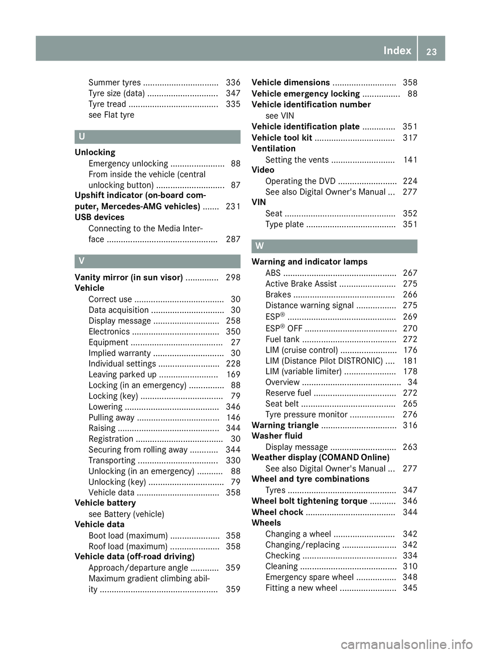
Summer tyres ................................ 336
Tyre size (data
).............................. 347
Tyre tread ...................................... 335
see Flat tyre U
Unlocking Emergency unlocking ....................... 88
From inside the vehicle (central
unlocking button) ............................. 87
Upshift indicator (on-board com-
puter, Mercedes-AMG vehicles) ....... 231
USB devices
Connecting to the Media Inter-
face ............................................... 287 V
Vanity mirror (in sun visor) .............. 298
Vehicle
Correct use ...................................... 30
Data acquisition ............................... 30
Display message ............................ 258
Electronics ..................................... 350
Equipment ....................................... 27
Implied warranty .............................. 30
Individual settings .......................... 228
Leaving parked up ......................... 169
Locking (in an emergency) ............... 88
Locking (key) ................................... 79
Lowering ........................................ 346
Pulling away ................................... 146
Raising ........................................... 344
Registration ..................................... 30
Securing from rolling away ............ 344
Transporting .................................. 330
Unlocking (in an emergency) ........... 88
Unlocking (key) ................................ 79
Vehicle data ................................... 358
Vehicle battery
see Battery (vehicle)
Vehicle data
Boot load (maximum) ..................... 358
Roof load (maximum) ..................... 358
Vehicle data (off-road driving)
Approach/departure angle ............ 359
Maximum gradient climbing abil-
ity .................................................. 359 Vehicle dimensions
........................... 358
Vehicle emergency locking ................ 88
Vehicle identification number
see VIN
Vehicle identification plate .............. 351
Vehicle tool kit .................................. 317
Ventilation
Setting the vents ........................... 141
Video
Operating the DVD ......................... 224
See also Digital Owner's Manua l... 277
VIN
Seat ............................................... 352
Type plate ...................................... 351 W
Warning and indicator lamps ABS ................................................ 267
Active Brake Assist ........................ 275
Brakes ........................................... 266
Distance warning signal ................. 275
ESP ®
.............................................. 269
ESP ®
OFF ....................................... 270
Fuel tank ........................................ 272
LIM (cruise control )........................ 176
LIM (Distance Pilot DISTRONIC ).... 181
LIM (variable limiter) ...................... 178
Overview .......................................... 34
Reserve fuel ................................... 272
Seat belt ........................................ 265
Tyre pressure monitor ................... 276
Warning triangle ................................ 316
Washer fluid
Display message ............................ 263
Weather display (COMAND Online)
See also Digital Owner's Manua l... 277
Wheel and tyre combinations
Tyres .............................................. 347
Wheel bolt tightening torque ........... 346
Wheel chock ...................................... 344
Wheels
Changing a whee l.......................... 342
Changing/replacing ....................... 342
Checking ........................................ 334
Cleaning ......................................... 310
Emergency spare wheel ................. 348
Fitting a new wheel ........................ 345 Index
23
Page 32 of 369
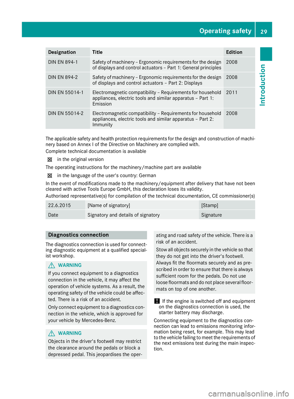
Designation Title Edition
DIN EN 894-1 Safety of machinery – Ergonomic requirements for the design
of displays and control actuators – Part 1: General principles 2008
DIN EN 894-2 Safety of machinery – Ergonomic requirements for the design
of displays and control actuators – Part 2: Displays 2008
DIN EN 55014-1 Electromagnetic compatibility – Requirements for household
appliances, electric tools and similar apparatus – Part 1:
Emission 2011
DIN EN 55014-2 Electromagnetic compatibility – Requirements for household
appliances, electric tools and similar apparatus – Part 2:
Immunity 2008
The applicable safety and health protection requirements for the design and construction of machi-
nery based on Annex I of the Directive on Machinery are complied with.
Complete technical documentation is available
1 in the original version
The operating instructions for the machinery/machine part are available
1 in the language of the user's country: German
In the event of modifications made to the machinery/equipment after delivery that have not been cleared with active Tools Europe GmbH, this declaration loses its validity.
Authorised representative(s) for compilation of the technical documentation, CE commissioner(s) 22.6.2015 [Name of signatory] [Stamp]
Date Signatory and details of signatory Signature
Diagnostics connection
The diagnostics connection is used for connect- ing diagnostic equipment at a qualified special-
ist workshop. G
WARNING
If you connect equipment to a diagnostics
connection in the vehicle, it may affect the
operation of vehicle systems. As a result, the operating safety of the vehicle could be affec-
ted. There is a risk of an accident.
Only connect equipment to a diagnostics con-
nection in the vehicle, which is approved for
your vehicle by Mercedes-Benz. G
WARNING
Objects in the driver's footwell may restrict
the clearance around the pedals or block a
depressed pedal. This jeopardises the oper- ating and road safety of the vehicle. There is a
risk of an accident.
Stow all objects securely in the vehicle so that
they do not get into the driver's footwell.
Always fit the floormats securely and as pre-
scribed in order to ensure that there is always sufficient room for the pedals. Do not use
loose floormats and do not place several floor-mats on top of one another.
! If the engine is switched off and equipment
on the diagnostics connection is used, the
starter battery may discharge.
Connecting equipment to the diagnostics con-
nection can lead to emissions monitoring infor-
mation being reset, for example. This may lead
to the vehicle failing to meet the requirements of
the next emissions test during the main inspec- tion. Operating safety
29Introduction Z
Page 35 of 369
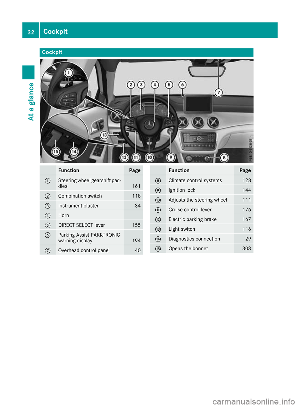
Cockpit
Function Page
:
Steering wheel gearshift pad-
dles 161
;
Combination switch 118
=
Instrument cluster 34
?
Horn
A
DIRECT SELECT lever 155
B
Parking Assist PARKTRONIC
warning display
194
C
Overhead control panel 40 Function Page
D
Climate control systems 128
E
Ignition lock 144
F
Adjusts the steering wheel 111
G
Cruise control lever 176
H
Electric parking brake 167
I
Light switch 116
J
Diagnostics connection 29
K
Opens the bonnet 30332
CockpitAt a glance
Page 36 of 369
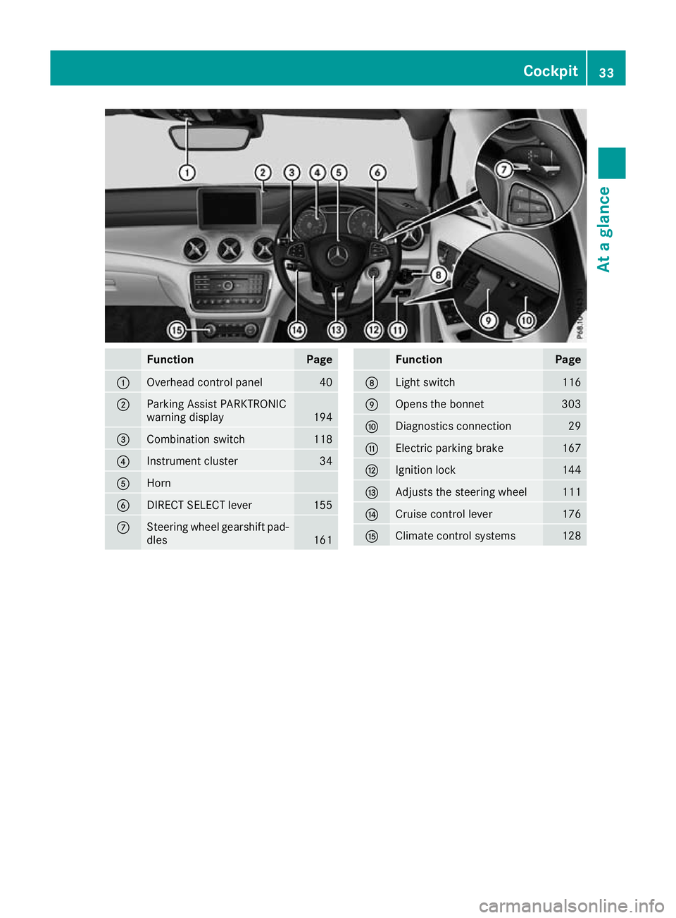
Function Page
:
Overhead control panel 40
;
Parking Assist PARKTRONIC
warning display
194
=
Combination switch 118
?
Instrument cluster 34
A
Horn
B
DIRECT SELECT lever 155
C
Steering wheel gearshift pad-
dles 161 Function Page
D
Light switch 116
E
Opens the bonnet 303
F
Diagnostics connection 29
G
Electric parking brake 167
H
Ignition lock 144
I
Adjusts the steering wheel 111
J
Cruise control lever 176
K
Climate control systems 128Cockpit
33At a glance
Page 42 of 369
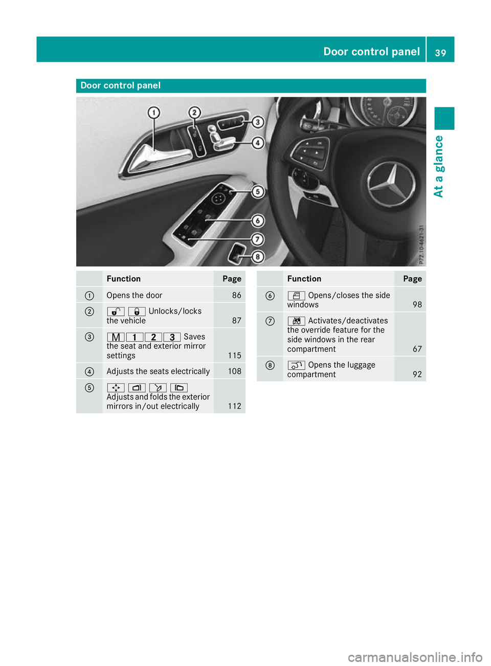
Door control panel
Function Page
:
Opens the door 86
;
%&Unlocks/locks
the vehicle
87
=
r45=
Saves
the seat and exterior mirror
settings 115
?
Adjusts the seats electrically 108
A
7
Zö\
Adjusts and folds the exterior
mirrors in/out electrically 112 Function Page
B
W
Opens/closes the side
windows 98
C
n
Activates/deactivates
the override feature for the
side windows in the rear
compartment 67
D
q
Opens the luggage
compartment 92Door control panel
39At a glance
Page 44 of 369
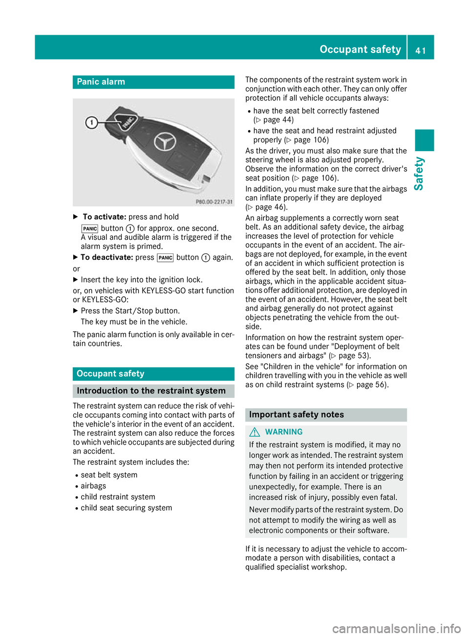
Panic alarm
X
To activate: press and hold
! button :for approx. one second.
A visual and audible alarm is triggered if the
alarm system is primed.
X To deactivate: press!button :again.
or
X Insert the key into the ignition lock.
or, on vehicles with KEYLESS-GO start function
or KEYLESS ‑GO:
X Press the Start/Stop button.
The key must be in the vehicle.
The panic alarm function is only available in cer-
tain countries. Occupant safety
Introduction to the restraint system
The restraint system can reduce the risk of vehi-
cle occupants coming into contact with parts of
the vehicle's interior in the event of an accident. The restraint system can also reduce the forces
to which vehicle occupants are subjected during an accident.
The restraint system includes the:
R seat belt system
R airbags
R child restraint system
R child seat securing system The components of the restraint system work in
conjunction with each other. They can only offerprotection if all vehicle occupants always:
R have the seat belt correctly fastened
(Y page 44)
R have the seat and head restraint adjusted
properly (Y page 106)
As the driver, you must also make sure that the
steering wheel is also adjusted properly.
Observe the information on the correct driver's
seat position (Y page 106).
In addition, you must make sure that the airbags can inflate properly if they are deployed
(Y page 46).
An airbag supplements a correctly worn seat
belt. As an additional safety device, the airbag
increases the level of protection for vehicle
occupants in the event of an accident. The air-
bags are not deployed, for example, in the event
of an accident in which sufficient protection is
offered by the seat belt. In addition, only those
airbags, which in the applicable accident situa-
tions offer additional protection, are deployed in the event of an accident. However, the seat beltand airbag generally do not protect against
objects penetrating the vehicle from the out-
side.
Information on how the restraint system oper-
ates can be found under "Deployment of belt
tensioners and airbags" (Y page 53).
See "Children in the vehicle" for information on
children travelling with you in the vehicle as well
as on child restraint systems (Y page 56). Important safety notes
G
WARNING
If the restraint system is modified, it may no
longer work as intended. The restraint system
may then not perform its intended protective function by failing in an accident or triggering
unexpectedly, for example. There is an
increased risk of injury, possibly even fatal.
Never modify parts of the restraint system. Do not attempt to modify the wiring as well as
electronic components or their software.
If it is necessary to adjust the vehicle to accom- modate a person with disabilities, contact a
qualified specialist workshop. Occupant safety
41Safety Z
Page 46 of 369
tion system" (Y
page 49) and on "Children in
the vehicle" (Y page 56).
R All other persons: the PASSENGER AIR BAG
OFF indicator lamp must be off. The front-
passenger front airbag is enabled. Depending
on the build of the person on the front-
passenger seat, the PASSENGER AIR BAG
OFF indicator lamp may light up. The front-
passenger front airbag is disabled. It will then
not be deployed in the event of an accident. In this case, the front-passenger seat should not
be used.
Make sure that you read the notes on the
"Automatic front-passenger front airbag
deactivation system" (Y page 49) as well as
on "Seat belts" (Y page 43) and "Airbags"
(Y page 46). There, you can also find infor-
mation on the correct seat position. Seat belts
Introduction A correctly worn seat belt is the most effective
means of restraining the movement of vehicle
occupants in the event of a collision or if the
vehicle overturns. This reduces the risk of vehi-
cle occupants coming into contact with parts of
the vehicle interior or being ejected from it. The seat belt also helps to keep the vehicle occu-
pants in the best position in relation to the air-
bag being deployed.
The seat belt system consists of:
R seat belts
R belt tensioners for the front seat belts and the
outer seat belts in the rear
R belt force limiters for the front seat belts and
the outer seat belts in the rear
If the seat belt is pulled quickly or sharply from
the belt outlet, the inertia reel locks. The belt
strap cannot be pulled out any further.
The belt tensioner tightens the seat belt in the
event of a collision so that it fits tightly across
your body. However, it does not pull the vehicle
occupants back in the direction of the seat
backrest.
The belt tensioner does not, however, correct an
incorrect seat position or correct the routing of a seat belt that is worn incorrectly.
When triggered, seat belt force limiters help to
reduce the peak force exerted by the seat belt
on the vehicle occupant. The belt force limiters on the front seats are
synchronised with the front airbags, which take
on a part of the deceleration force. This can
reduce the forces to which the vehicle occu-
pants are subjected during an accident.
! If the front-passenger seat is not occupied,
do not engage the seat belt tongue in the
buckle on the front-passenger seat. Other-
wise, the belt tensioner and sidebag could be
triggered in the event of an accident and
would need to be replaced.
Important safety notes G
WARNING
If the seat belt is worn incorrectly, it cannot
perform its intended protective function. Fur- thermore, an incorrectly worn seat belt can
cause additional injuries, e.g. in the event of
an accident, heavy braking or sudden
changes of direction. There is an increased
risk of injury, possibly even fatal.
Always ensure that all vehicle occupants have their seat belts fastened correctly and are sit-
ting properly.
The components of the restraint system work in
conjunction with each other. They can only offer protection if all vehicle occupants always:
R have the seat belt correctly fastened
(Y page 44)
R have the seat and head restraint adjusted
properly (Y page 106) G
WARNING
The seat belt does not offer the intended level of protection if you have not moved the back-
rest to an almost vertical position. When brak-
ing or in the event of an accident, you could
slide underneath the seat belt and sustain
abdomen or neck injuries, for example. This
poses an increased risk of injury or even fatal injury.
Adjust the seat properly before beginning
your journey. Always ensure that the backrest
is in an almost vertical position and that the
shoulder section of your seatbelt is routed
across the centre of your shoulder. Occupant safety
43Safety Z
Page 52 of 369
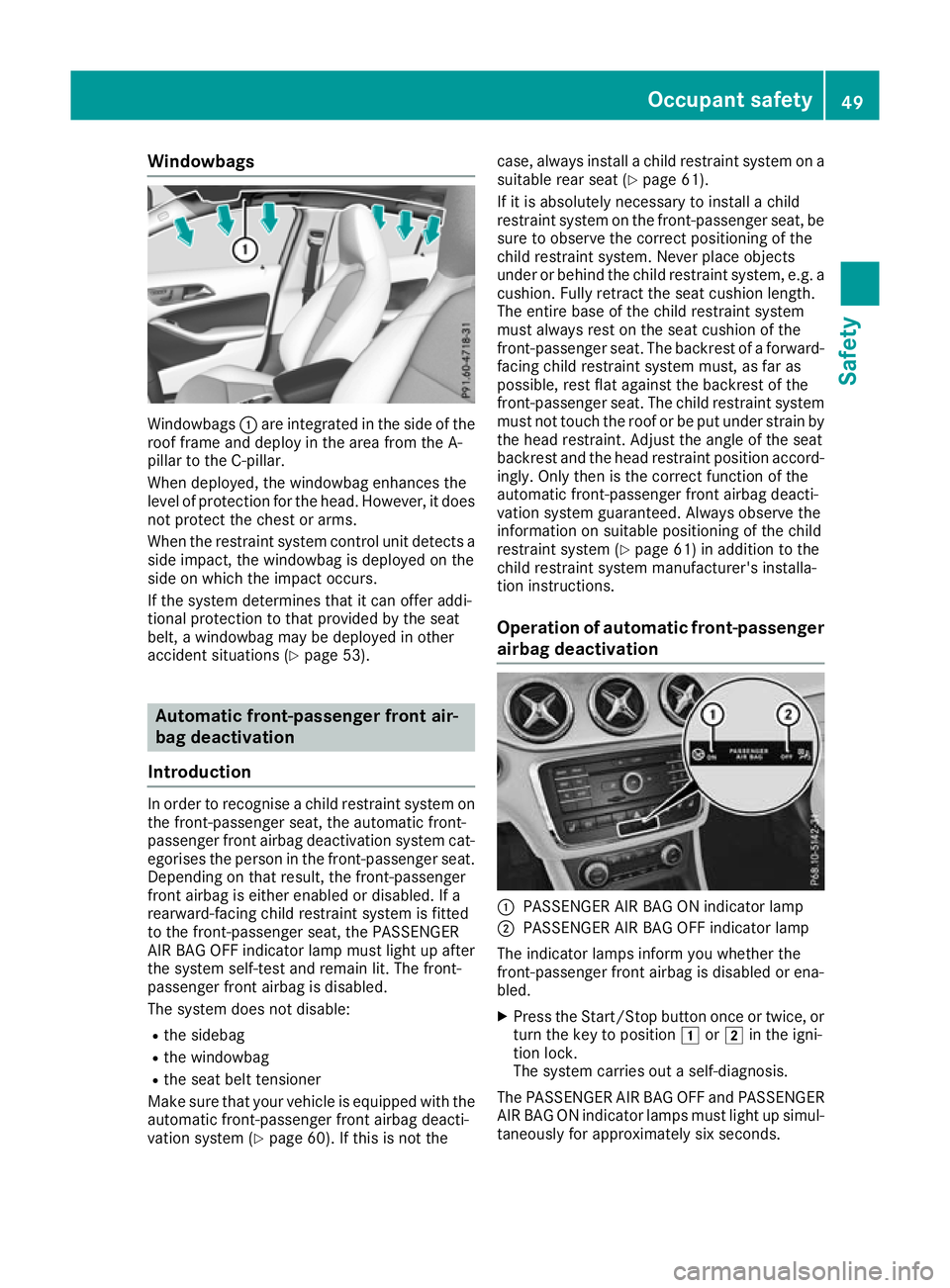
Windowbags
Windowbags
:are integrated in the side of the
roof frame and deploy in the area from the A-
pillar to the C-pillar.
When deployed, the windowbag enhances the
level of protection for the head. However, it does
not protect the chest or arms.
When the restraint system control unit detects a side impact, the windowbag is deployed on the
side on which the impact occurs.
If the system determines that it can offer addi-
tional protection to that provided by the seat
belt, a windowbag may be deployed in other
accident situations (Y page 53).Automatic front-passenger front air-
bag deactivation
Introduction In order to recognise a child restraint system on
the front-passenger seat, the automatic front-
passenger front airbag deactivation system cat- egorises the person in the front-passenger seat.Depending on that result, the front-passenger
front airbag is either enabled or disabled. If a
rearward-facing child restraint system is fitted
to the front-passenger seat, the PASSENGER
AIR BAG OFF indicator lamp must light up after
the system self-test and remain lit. The front-
passenger front airbag is disabled.
The system does not disable:
R the sidebag
R the windowbag
R the seat belt tensioner
Make sure that your vehicle is equipped with the automatic front-passenger front airbag deacti-
vation system (Y page 60). If this is not the case, always install a child restraint system on a
suitable rear seat (Y page 61).
If it is absolutely necessary to install a child
restraint system on the front-passenger seat, be
sure to observe the correct positioning of the
child restraint system. Never place objects
under or behind the child restraint system, e.g. a
cushion. Fully retract the seat cushion length.
The entire base of the child restraint system
must always rest on the seat cushion of the
front-passenger seat. The backrest of a forward-
facing child restraint system must, as far as
possible, rest flat against the backrest of the
front-passenger seat. The child restraint system must not touch the roof or be put under strain bythe head restraint. Adjust the angle of the seat
backrest and the head restraint position accord-
ingly. Only then is the correct function of the
automatic front-passenger front airbag deacti-
vation system guaranteed. Always observe the
information on suitable positioning of the child
restraint system (Y page 61) in addition to the
child restraint system manufacturer's installa-
tion instructions.
Operation of automatic front-passenger
airbag deactivation :
PASSENGER AIR BAG ON indicator lamp
; PASSENGER AIR BAG OFF indicator lamp
The indicator lamps inform you whether the
front-passenger front airbag is disabled or ena-
bled.
X Press the Start/Stop button once or twice, or
turn the key to position 1or2 in the igni-
tion lock.
The system carries out a self-diagnosis.
The PASSENGER AIR BAG OFF and PASSENGER
AIR BAG ON indicator lamps must light up simul- taneously for approximately six seconds. Occupant safety
49Safety Z