2017 MERCEDES-BENZ E-CLASS ESTATE load capacity
[x] Cancel search: load capacityPage 257 of 585
Tr
aile rhitch Tr
aile roperation no tes Mercedes‑AMG
vehicles: alwayso bser vethe
no tesint he Supplement. Otherwise, youm ay
fa ilto recognise dangers.
Obser vethef ollowing no tesont hetongue
we ight:
R use atongue weight as clos easpossible to
th em aximum tongu eweight
R do no tuse atongue weight that exc eeds or
fa lls belo wthe permissible tongu eweight
Do no texceed thef ollowing values:
R thep ermissible towing capacity
R thep ermissible rear axle load of thet ow ing
ve hicle
R thep ermissible gross mass of thet ow ing
ve hicle
R thep ermissible gross mass of thet railer
R them aximum permissible speed of thet railer Mak
esureoft hefollowing befor estartin gaj our‐
ney:
R thet yrep ressur eont herear axle of thet ow‐
ing vehicle is se tfor am aximu mload
R thel ighting of thec onnected trailer is opera‐
tional
R Vehicles without LED headlamps or MUL‐
TIBEA MLED headlamps: The headlamps
ha ve been se tcorrectly.
In thee vent of increased rear axle load, thec ar/
trailer combination ma ynot exc eedamaximum
speed of 100k m/h forr easons concerning the
operating permit. This also applies in countri es
in whic hthe permissible maximum speed for
car/traile rcombinations is ab ove1 00 km/h. Extending/
retracting the bal lneckf ullye lec‐
trically &
WARNING Risk of accident du etothe
ball nec knotbeing engaged
If th eb all nec kisnotengaged, thet railer
ma ycome loose. #
Mak esuret hat theb all nec ksecurely
engages and loc ksintop lace. *
NO
TEDama getothef ully-electric trailer
hitch The fully-elect
rict railer hitchcould be
mechanically damaged byapplying additional
pressur ewhen theb all nec kisbeingexten‐
de dorr etra cted. #
Do no tmaket he ball nec kextend/
re tract faster by applying additional
pressure. Re
quirements:
Mak esureoft hefollowing befor eextending/
re tracting theb all nec kfullye lectrically:
R Shif tthe transmission toposition jori.
R The rang eofm ovement is clear.
R Onl yw hen retracting: remo vethet railer
cables or adap terp lugs. 254
Driving and parking
Page 261 of 585
*
NO
TEDama getother ear bumper from
ins talling adap terc ables or adapte rplugs The
following parts could be damaged when
re tracting theb all nec kfullye lectrically:
R bumper
R adap terc able
R adapte rplug #
Alw aysr emo vethea dap terc ableor
adapte rplugb efor eretra cting theb all
nec kfullye lectrically. #
Safeguar dthe trailer agains trolling away. #
Disconnect thee lectrical connection
between thev ehicle and thet railer. #
Uncoupl ethe trailer. #
Place thec over on theb all head. Bicycle
rack &
WARNING Risk of an accident when
using theb icycle rack incor rectly
The bicycle rack ma ybecome de tach ed from
th ev ehicle in thef ollowing cases:
R thep ermissible load capacity of the
traile rhitch isexceeded.
R theb icycle rack is used incor rectl y.
R theb icycle rack is secured totheb all
nec kbeneat hthe ball head.
Obser vethef ollowing fory our owns afety
and that of other road users:
R alwaysa dher etot he permissible load
capacity of thet railer hitch.
R onlyusetheb icycle rack totranspo rt
bicycles.
R alwaysm ount theb icycle rack properly by
attachin gtothe ball head and theb all
nec kguide pin, if possible. R
when transporting four bic ycles, alw ays
use bic ycle rack sw hichh ave additional
suppo rton theb all nec kguide pin.
R onlyuse bicycle rack sa ppr ove dby
Mercedes-Benz.
R alwayso bser vetheb icycle rack operating
instructions. *
NO
TEDama getoor crac kson thet railer
hitc hduetounsuitable bic ycle rack sor
bicycle rack sb eing used incor rectly #
Onlyusebicycle rack sa ppr ove dby
Mercedes-Benz. 258
Driving and parking
Page 262 of 585
Tr
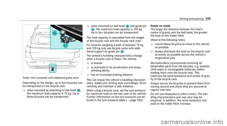
ailer hit ch(examp le withadditional guide pins)
Depending on thed esign, up tofour bic ycles can
be transpor tedont he bicycle rack:
R when moun tedbya ttachin gtoball head 1,
th em aximum load capacity is 75kg.Upto
th re eb icycles can be transpor ted. R
when mounted on ball head 1and guide pin
2,t he maximum load capacity is 100k g.
Up tofour bic ycles can be transpo rted.
The load capacity is calculated from thew eight
of theb icycle rack and theb icycle rack load.
Fo rb icycles weighin gatotal of between 75kg
and 100k gonlyu se bicycle rack sw itha ddi‐
tional suppor tonguide pin 2.
The vehicle's handling characteristic schange
when abicycle rack isfitted .The vehicle:
R is heavier
R isrestricted in its accele ratio na nd slope
climbing ability.
R hasani ncrease dbraking di stance
This can impair thev ehicle's handling character‐
istics. Adapty our driving stylea ccordingly .Drive
carefully and maintain asafed ista nce.
Whe nusing abicyc le rack ,set thet yrep ressure
fo rm aximu mloadont herear axle of thev ehicle.
Fu rther information on thet yrep ressur ecan be
fo und in thet yrep ressur etable (→ page430). Note
sonl oads
The larger thed ista nce betwee nthe load's
centre of gravity and theb all head, theg reater
th el oad on thet railer hitch.
Obser vethef ollowing no tes:
R mount heavy bicycles as close tothev ehicle
as possible.
R alwaysd istribut ethe load on theb icycle rack
as evenl yasp ossible across thev ehicle's
longitudinal axis.
Mercedes-Ben zrecommends removing all
de tac hable parts from theb icycles, e.g. bask ets,
ch ild seats or rech arge able bat teries, before
loading them ont othe bicycle rack .T his
impr ovesthe wind resis tance and centr eofgrav‐
ity of theb icycle rack.
Alw ayss ecur ethe bicycles topreve ntthem from
moving around and checkt heya resecured at
re gular inter vals.
Do no tuse tarp aulins or other co vers.T he han‐
dling characteristic sand rear vie wmaybe
impaired. In addition ,the wind resis tance and
load on thet railer hitc hincrease. Driving and parking
259
Page 440 of 585
Yo
uc an ask fori nformation rega rding permit ted
wheel/tyr ecombinations at aMercedes-Benz
Servic eCentre. &
WARNING Risk of accident du etoincor‐
re ct dimensions of wheel sand tyres
If wheel sand tyres of thew rong size are
used, thew heel brakes or wheel suspension
components ma ybecome damaged. #
Alw aysr eplace wheels and tyres with
th ose that fulfil thes pecification softhe
original part.
When replacing wheels, mak esuretof itthe
cor rect:
R Designation
R Type
When replacing tyres, mak esuretof itthe
cor rect:
R Designation
R Manufactu rer
R Type &
WARNING Risk of inju rythro ugh exceed‐
ing thes pecified tyr eload-bearing capa‐
city or thep ermissible speed rating
Exceeding thes pecified tyr eload-bearing
capacity or thep ermissible speed rating may
lead totyr ed amag eand tothet yres bur st‐
ing. #
Therefore, onl yuse tyr etypes and sizes
appr ovedfor your vehicle model. #
Obser vethet yrel oad-bearing capacity
ra ting and spee drating requiredfor
yo ur vehicle. *
NO
TEDama getovehicle and tyres due
to non-app rove dt yret ypes and sizes Fo
rs afet yr easons, onl yuse wheels, tyres
and accessories whic hhave been appr oved
fo ry our vehicle byMercedes-Benz. These tyres ha
vebeen speciall yadap tedf or
use wit hthe control sy stems, e.g. ABS or
ESP ®
,a nd ar emarke dasf ollows:
R MO =Mercedes-BenzO riginal
R MOE =Mercedes-BenzO riginal Extended
(run-flat tyres onl yfor cer tain wheels)
R MO1 =Mercedes-Benz Original (onl ycer‐
ta in AMG tyres)
Cer tain characteristics, e.g .handling, vehicle
noise emissions or fuel consum ption, may
ot herwise be adversely af fected. In addition,
whe ndriving wi thaload, tyr edimension var‐
iations could caus ethe tyres tocome into
contact wi th thebody and axle components.
This could result in damag etothe tyres or
th ev ehicle.
Onl yuse tyres, wheels or accessories tested
and appr oved byMercedes-Benz. Wheels and tyres
437
Page 465 of 585
Ve
hicl eheight Model
E2
00 4MATIC
E2 20 d4MATIC 14
81 mm
E3 50 d1 476mm
E3 50 d4MATIC 1482 mm
E4 00 4MATIC 14 67mm
All other models 1475 mm We
ight sand loads Please no
tethat fort he specified vehicle data:
R items of optional equipment increase the
unladen weight and reduce thep ayload.
R vehicle-specific weight informatio ncan be
fo und on thev ehicle identification plat e.
Ro of load All models
Maximum
roof load 100kg Tr
aile rhitch Gene
raln otes on thet railer hit ch No
tall models can be used to towat railer
(→ pag e254).
Modifications tothee ngine cooling sy stem may
be necessar y,dependin gonthevehicle model.
The retrofitting of atrailer hitchiso nly pe rmissi‐
ble if atow ing capacity is specified in your vehi‐
cle documents.
Fu rther information can be obtained at aquali‐
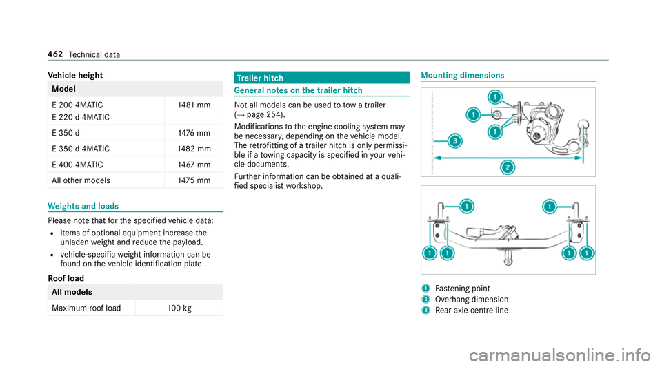
fi ed specialis tworks hop. Mounting dimensions
1
Fastening point
2 Overhang dimension
3 Rear axle centr eline 462
Tech nica ldata
Page 466 of 585
The
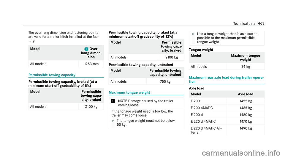
overhang dimension and fastening points
ar ev alid forat railer hitc hinstalled at thef ac‐
to ry. Model
2 2Over‐
hang dimen‐ sion
All model s1 253 mmPe
rm issible towing capacity Pe
rm issible towing capacit y,braked (at a
minimum start-of fgradeability of 8%) Model
Perm issible
to wing capa‐
cit y,braked
All models 2100 kg Pe
rm issible towing capacit y,braked (at a
minimum start-of fgradeability of 12%) Model
Perm issible
to wing capa‐
cit y,braked
All models 2100 kg Pe
rm issible towing capacit y,unbraked Model
Perm issible towing
capacit y,unbraked
All model s7 50kg Maximum
tongue weight *
NO
TEDama gecaused bythet railer
comin gloose If
th et ongue weight used is tool ow ,the
trailer ma ycome loose. #
Thet ongue weight mus tnotbe below
50 kg. #
Use atongue weight that is as close as
possible tothem aximum permissible
to ngu eweight. To
ngue weight Model
Maximumtongue
we ight
All models 84 kg Maximum
rear axle load during traile ropera‐
tion Axl
eload Model
Axleload
E2 00 1455 kg
E2 00 4MATIC 1465 kg
E2 00 d1 480kg
E2 20 d4MATIC 1470 kg
E2 20 d4MATIC All-
Te rrain 14
90 kg Te
ch nica ldata 463
Page 576 of 585
HANDS-FREE
ACCES S........................... 79
Limiting theo pening angle .................... 80
Openin g.................................................75
Opening dimensions ............................4 61
Un lockin g(emer gency key) .................. .80
Ta ilgate
see Locking/unlocking
Ta ke -bac kofe nd-of-lif evehicles .............. 21
Pr otection of thee nvironmen t............... 21
Ta nk capacity
Ad Blue ®
............................................... 457
Fu el ..................................................... 456
Re ser ve(fuel) ...................................... 456
Te ch nical data
Axle load (trailer operation) ................. 463
Fa stening point (trailer hitch) .............. 462
Information .......................................... 448
Mounting dimensions (trailer hitch) ..... 462
No tes( trailerh itch) ............................. 462
Overhang dimension (trailerh itch) ...... 462
To ngu eweight .................................... .463
To wing weight (t owing atrailer) .......... .463
Ty re pressur emonitoring sy stem ........ 433
Ve hicle identification plat e.................. 450 Te
lephone ........................................ 270, 335
Ac tivating functions du ring acall. ....... 342
Au thorising amobile phone (Remo te
Pa rking Assist) .................................... .242
Business telephon ysettings ................ 339
Call and ringtone volume .................... .341
Calls wit hseveral participant s............. 342
Connecting amobile phone (busi‐
ness telephony) .................................. .338
Connecting amobile phone (Near
Fiel dCommunicatio n(NFC)) .............. .340
Connecting amobile phone (Pass‐
ke y) .................................................... .337
Connecting amobile phon e(Secure
Simple Pairing) .................................... 337
Disconnecting amobile phon e........... .340
Importin gcontacts .............................. 343
Incoming cal ldurin gane xisting call .... 342
In fo rm atio n......................................... .336
Lockin gthe vehicle (mobile phone) .......71
Menu (on-boar dcomputer) .................. 270
Mobile phone voice recognition ........... 341
No tes. ................................................. 336
Operating modes ................................. 336
Re ception and transmission volume .... 341
St artin gthe vehicle (mobile phone) ..... 16 8Switching mobil
ephones .................... 339
Switching mobil ephones (Near Field
Communication (NFC)) ........................ 340
Symbol sfor business telephon y......... .339
Te lephon emenuo verview. ..................3 35
Te lephon eoperation ............................ 341
Un lockin gthe vehicle (mobile phone) ....71
Using aSIM car dfor business tel‐
ephon y............................................... .338
Usin gNear Field Communication
(NFC) .................................................. .340
Vo ice command s(LINGU ATRO NIC) .....2 80
Wi reless chargin g(mobile phone) ........ 13 2
Te lephone number
Dialling (on-boar dcomputer) .............. .270
Te lephone operation
see Calls
Te lephon yoperating modes
Blue tooth ®
Te lephon y......................... .336
Business telephon y............................. 336
Te lete xt
Displaying ............................................ 387
Overvie w............................................. 387 Index
573