2017 KIA Sportage Seat position
[x] Cancel search: Seat positionPage 340 of 595
Driving your vehicle
14
6
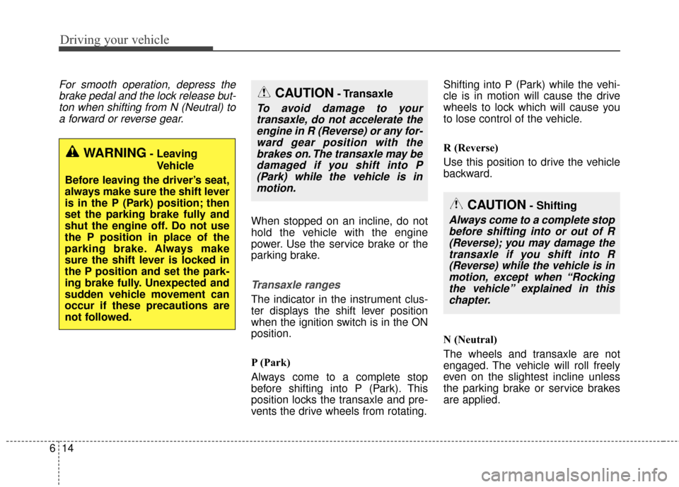
For smooth operation, depress the
brake pedal and the lock release but-ton when shifting from N (Neutral) toa forward or reverse gear.
When stopped on an incline, do not
hold the vehicle with the engine
power. Use the service brake or the
parking brake.
Transaxle ranges
The indicator in the instrument clus-
ter displays the shift lever position
when the ignition switch is in the ON
position.
P (Park)
Always come to a complete stop
before shifting into P (Park). This
position locks the transaxle and pre-
vents the drive wheels from rotating. Shifting into P (Park) while the vehi-
cle is in motion will cause the drive
wheels to lock which will cause you
to lose control of the vehicle.
R (Reverse)
Use this position to drive the vehicle
backward.
N (Neutral)
The wheels and transaxle are not
engaged. The vehicle will roll freely
even on the slightest incline unless
the parking brake or service brakes
are applied.
WARNING- Leaving
Vehicle
Before leaving the driver’s seat,
always make sure the shift lever
is in the P (Park) position; then
set the parking brake fully and
shut the engine off. Do not use
the P position in place of the
parking brake. Always make
sure the shift lever is locked in
the P position and set the park-
ing brake fully. Unexpected and
sudden vehicle movement can
occur if these precautions are
not followed.
CAUTION- Transaxle
To avoid damage to your transaxle, do not accelerate theengine in R (Reverse) or any for-ward gear position with thebrakes on. The transaxle may bedamaged if you shift into P(Park) while the vehicle is inmotion.
CAUTION- Shifting
Always come to a complete stopbefore shifting into or out of R(Reverse); you may damage thetransaxle if you shift into R(Reverse) while the vehicle is inmotion, except when “Rockingthe vehicle” explained in thischapter.
Page 359 of 595
633
Driving your vehicle
To release EPB (electronic parking
brake) automatically:
Shift lever in P (Park)With the engine running depress
the brake pedal and shift out of P
(Park) to R (Reverse) or D (Drive).
Shift lever in N (Neutral) With the engine running depress
the brake pedal and shift out of N
(Neutral) to R (Reverse) or D
(Drive).
Automatic Transaxle 1. Start the engine.
2. Fasten the driver's seat belt.
3. Close the driver's door, engine hood and tailgate.
4. Depress the accelerator pedal while the shift lever is in R (Rear),
D (Drive) or manual mode.
Make sure the brake warning light
goes off.✽ ✽ NOTICE
• For your safety, you can engage
the EPB even though the ignition
switch or engine stop/start button
is in the OFF position, but you
cannot release it.
• For your safety, depress the brake pedal and release the parking
brake manually with the EPB
switch when you drive downhill or
when backing up the vehicle.
Do not follow the above procedure
when driving on a flat level ground.
The vehicle may suddenly move for-
ward.
✽ ✽ NOTICE
If the parking brake warning light is
still on even though the EPB has
been released, have the system
checked by an authorized Kia dealer.
EPB (electronic parking brake) may
be automatically applied when:
The EPB is overheated
Requested by other systems
✽ ✽NOTICE
If the driver turns the engine off by
mistake while Auto Hold is operat-
ing, EPB will be automatically
applied. (Vehicles equipped with
Auto Hold)
CAUTION
Do not drive your vehicle with
the EPB applied. It may causeexcessive brake pad and brakerotor wear.
Page 430 of 595
Driving your vehicle
104
6
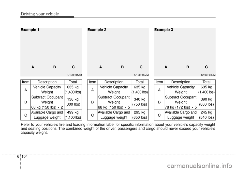
Refer to your vehicle’s tire and loading information label for specific information about your vehicle's capacity weight
and seating positions. The combined weight of the driver, passengers and cargo should never exceed your vehicle's
capacity weight.
C190F01JM
Item Description Total
A Vehicle Capacity 635 kg
Weight (1,400 lbs)
Subtract Occupant
B Weight 136 kg
68 kg (150 lbs) × 2 (300 lbs)
C
Available Cargo and499 kg
Luggage weight (1,100 lbs)
Example 1
ABC
C190F02JM
Item Description TotalA Vehicle Capacity 635 kg
Weight (1,400 lbs)
Subtract Occupant
B Weight 340 kg
68 kg (150 lbs) × 5 (750 lbs)
C
Available Cargo and295 kg
Luggage weight (650 lbs)
ABC
Example 2
C190F03JM
Item Description Total
A Vehicle Capacity 635 kg
Weight (1,400 lbs)
Subtract Occupant
B Weight 390 kg
78 kg (172 lbs) × 5 (860 lbs)
C
Available Cargo and245 kg
Luggage weight (540 lbs)
ABC
Example 3
Page 452 of 595
What to do in an emergency
20
7
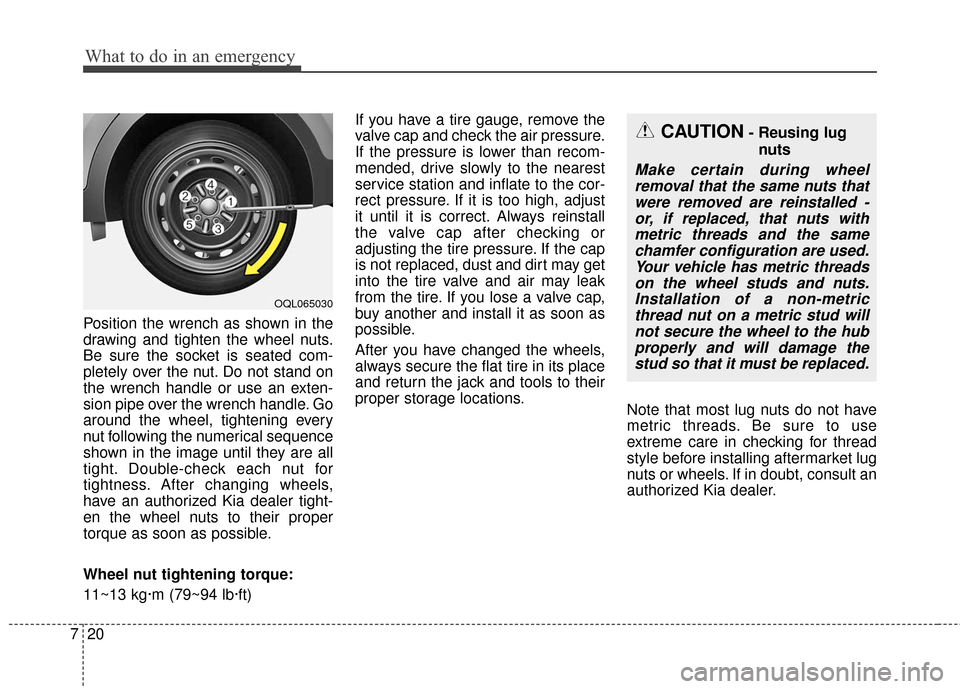
Position the wrench as shown in the
drawing and tighten the wheel nuts.
Be sure the socket is seated com-
pletely over the nut. Do not stand on
the wrench handle or use an exten-
sion pipe over the wrench handle. Go
around the wheel, tightening every
nut following the numerical sequence
shown in the image until they are all
tight. Double-check each nut for
tightness. After changing wheels,
have an authorized Kia dealer tight-
en the wheel nuts to their proper
torque as soon as possible.
Wheel nut tightening torque:
11~13 kg·m (79~94 lb·ft) If you have a tire gauge, remove the
valve cap and check the air pressure.
If the pressure is lower than recom-
mended, drive slowly to the nearest
service station and inflate to the cor-
rect pressure. If it is too high, adjust
it until it is correct. Always reinstall
the valve cap after checking or
adjusting the tire pressure. If the cap
is not replaced, dust and dirt may get
into the tire valve and air may leak
from the tire. If you lose a valve cap,
buy another and install it as soon as
possible.
After you have changed the wheels,
always secure the flat tire in its place
and return the jack and tools to their
proper storage locations.
Note that most lug nuts do not have
metric threads. Be sure to use
extreme care in checking for thread
style before installing aftermarket lug
nuts or wheels. If in doubt, consult an
authorized Kia dealer.
CAUTION- Reusing lug
nuts
Make certain during wheelremoval that the same nuts thatwere removed are reinstalled -or, if replaced, that nuts withmetric threads and the samechamfer configuration are used.Your vehicle has metric threadson the wheel studs and nuts.Installation of a non-metricthread nut on a metric stud willnot secure the wheel to the hubproperly and will damage thestud so that it must be replaced.
OQL065030
Page 525 of 595
857
Maintenance
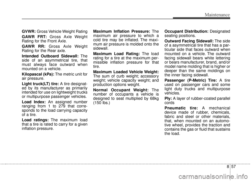
GVWR:Gross Vehicle Weight Rating
GAWR FRT: Gross Axle Weight
Rating for the Front Axle.
GAWR RR: Gross Axle Weight
Rating for the Rear axle.
Intended Outboard Sidewall: The
side of an asymmetrical tire, that
must always face outward when
mounted on a vehicle.
Kilopascal (kPa): The metric unit for
air pressure.
Light truck(LT) tire: A tire designat-
ed by its manufacturer as primarily
intended for use on lightweight trucks
or multipurpose passenger vehicles.
Load Index: An assigned number
ranging from 1 to 279 that corre-
sponds to the load carrying capacity
of a tire.
Load ratings: The maximum load
that a tire is rated to carry for a given
inflation pressure. Maximum Inflation Pressure:
The
maximum air pressure to which a
cold tire may be inflated. The maxi-
mum air pressure is molded onto the
sidewall.
Maximum Load Rating: The load
rating for a tire at the maximum per-
missible inflation pressure for that
tire.
Maximum Loaded Vehicle Weight:
The sum of curb weight; accessory
weight; vehicle capacity weight; and
production options weight.
Normal Occupant Weight: The
number of occupants a vehicle is
designed to seat multiplied by 68kg
(150 lbs.) Occupant Distribution:
Designated
seating positions.
Outward Facing Sidewall: The side
of a asymmetrical tire that has a par-
ticular side that faces outward when
mounted on a vehicle. The outward
facing sidewall bears white lettering
or bears manufacturer, brand, and/or
model name molding that is higher or
deeper than the same moldings on
the inner facing sidewall.
Passenger (P-Metric) Tire: A tire
used on passenger cars and some
light duty trucks and multipurpose
vehicles.
Ply: A layer of rubber-coated parallel
cords
Pneumatic tire: A mechanical
device made of rubber, chemicals,
fabric and steel or other materials,
that, when mounted on an automo-
tive wheel, provides the traction and
contains the gas or fluid that sustains
the load.
Page 526 of 595
Maintenance
58
8
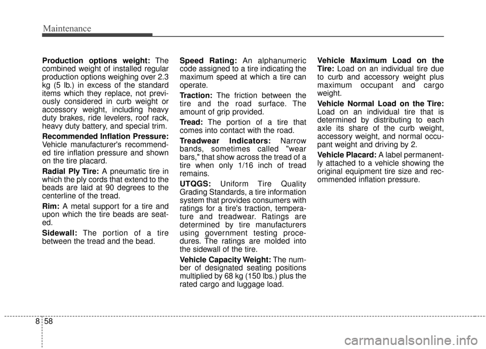
Production options weight: The
combined weight of installed regular
production options weighing over 2.3
kg (5 lb.) in excess of the standard
items which they replace, not previ-
ously considered in curb weight or
accessory weight, including heavy
duty brakes, ride levelers, roof rack,
heavy duty battery, and special trim.
Recommended Inflation Pressure:
Vehicle manufacturer's recommend-
ed tire inflation pressure and shown
on the tire placard.
Radial Ply Tire: A pneumatic tire in
which the ply cords that extend to the
beads are laid at 90 degrees to the
centerline of the tread.
Rim: A metal support for a tire and
upon which the tire beads are seat-
ed.
Sidewall: The portion of a tire
between the tread and the bead. Speed Rating:
An alphanumeric
code assigned to a tire indicating the
maximum speed at which a tire can
operate.
Traction: The friction between the
tire and the road surface. The
amount of grip provided.
Tread: The portion of a tire that
comes into contact with the road.
Treadwear Indicators: Narrow
bands, sometimes called "wear
bars," that show across the tread of a
tire when only 1/16 inch of tread
remains.
UTQGS: Uniform Tire Quality
Grading Standards, a tire information
system that provides consumers with
ratings for a tire's traction, tempera-
ture and treadwear. Ratings are
determined by tire manufacturers
using government testing proce-
dures. The ratings are molded into
the sidewall of the tire.
Vehicle Capacity Weight: The num-
ber of designated seating positions
multiplied by 68 kg (150 lbs.) plus the
rated cargo and luggage load. Vehicle Maximum Load on the
Tire:
Load on an individual tire due
to curb and accessory weight plus
maximum occupant and cargo
weight.
Vehicle Normal Load on the Tire:
Load on an individual tire that is
determined by distributing to each
axle its share of the curb weight,
accessory weight, and normal occu-
pant weight and driving by 2.
Vehicle Placard: A label permanent-
ly attached to a vehicle showing the
original equipment tire size and rec-
ommended inflation pressure.
Page 591 of 595
Index
6I
Air ventilation seat ....................................................4-167
Bottle holder ............................................................4-165
Cargo security screen ................................................4-175
Clothes hanger ..........................................................4-173
Cup holder ................................................................4-165
Floor mat anchor (s)..................................................\
4-173
Luggage net holder ..................................................4-174
Power outlet ..............................................................4-168
Seat warmer ..............................................................4-166
Sunvisor ....................................................................4-16\
7
USB charger ..............................................................4-169
Wireless smart phone charging system ....................4-170
Interior lights ..............................................................4-130 Automatic turn off function ......................................4-130
Glove box lamp ........................................................4-132
Liftgate room lamp ..................................................4-132
Map lamp ................................................................4-131
Room lamp ................................................................4-130
Vanity mirror lamp ....................................................4-132
Interior overview..............................................................2-4
Key positions ..................................................................6-6 Ignition switch position ................................................6-6
Illuminated ignition switch ..........................................6-6
Starting the engine ........................................................6-7 Lane departure warning system (LDWS) ......................6-80
Conditions that cause missed warnings andfalse warnings ..........................................................6-83
Conditions that cause the LDWS not to operate ........6-82
Warning indicator ......................................................6-82
LCD Display ..................................................................4-75 LCD Modes ................................................................4-75
Service Mode ..............................................................4-76
User Settings Mode ....................................................4-78
Liftgate (for manual liftgate) ........................................4-26 Closing the liftgate ......................................................4-26
Emergency liftgate safety release ..............................4-27
Opening the liftgate ....................................................4-26
Light bulbs ....................................................................8-80\
Back-up lamp and Rear turn signal lamp bulbreplacement ..............................................................8-89
Bulb replacement precaution ......................................8-80
Front fog lamp (Bulb and LED type) bulb replacement ..............................................................8-86
Front turn signal lamp bulb replacement ....................8-85
Glove box lamp bulb replacement ..............................8-93
Headlamp (HID type) bulb replacement ....................8-83
Headlamp (High/Low beam) bulb replacement..........8-84
High mounted stop lamp bulb replacement ................8-90
License plate lamp bulb Replacement ........................8-90
Light bulb position (Front) ........................................8-81
K
L