Page 301 of 470
65
What to do in an emergency
EMERGENCY STARTING
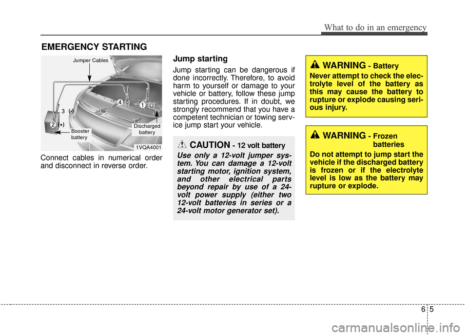
Connect cables in numerical order
and disconnect in reverse order.
Jump starting
Jump starting can be dangerous if
done incorrectly. Therefore, to avoid
harm to yourself or damage to your
vehicle or battery, follow these jump
starting procedures. If in doubt, we
strongly recommend that you have a
competent technician or towing serv-
ice jump start your vehicle.
CAUTION- 12 volt battery
Use only a 12-volt jumper sys-tem. You can damage a 12-voltstarting motor, ignition system,and other electrical partsbeyond repair by use of a 24-volt power supply (either two12-volt batteries in series or a24-volt motor generator set).
WARNING- Battery
Never attempt to check the elec-
trolyte level of the battery as
this may cause the battery to
rupture or explode causing seri-
ous injury.
1VQA4001
Discharged battery
Jumper Cables
Booster
battery
(-)
(+)
(+)(-)
WARNING- Frozenbatteries
Do not attempt to jump start the
vehicle if the discharged battery
is frozen or if the electrolyte
level is low as the battery may
rupture or explode.
Page 307 of 470
611
What to do in an emergency
TPMS (Tire Pressure
Monitoring System)
malfunction indicator
The TPMS malfunction indicator will
illuminate after it blinks for approxi-
mately one minute when there is a
problem with the Tire Pressure
Monitoring System. Have the system
checked by an authorized Kia dealer
as soon as possible to determine the
cause of the problem.
The TPMS malfunction indicatormay blink for approximately 1
minute and then remain continuous-
ly illuminated if the vehicle is moving
around electric power supply cables
or radios transmitters such as at
police stations, government and
public offices, broadcasting sta-
tions, military installations, airports,
or transmitting towers, etc. This can
interfere with normal operation of
the Tire Pressure Monitoring
System (TPMS). The TPMS malfunction indicator
may blink for approximately 1
minute and then remain continuous-
ly illuminated if snow chains are
used or some separate electronic
devices such as notebook comput-
er, mobile charger, remote starter or
navigation etc., are used in the vehi-
cle. This can interfere with normal
operation of the Tire Pressure
Monitoring System (TPMS).
WARNING- Low pressure
damage
Do not drive on low pressure
tires. Significantly low tire pres-
sure can cause the tires to over-
heat and fail making the vehicle
unstable resulting in increased
braking distances and a loss of
vehicle control.
Page 312 of 470
What to do in an emergency
16
6
0. Speed restriction label
1. Sealant bottle and label with
speed restriction
2. Filling hose from sealant bottle to wheel
3. Connectors and cable for the power outlet direct connection 4. Holder for the sealant bottle
5. Compressor
6. On/off switch
7. Pressure gauge for displaying the
tire inflation pressure
8. Screw cap for reducing tire infla- tion pressure 9. Hose to connect compressor and
sealant bottle or compressor and
wheel
Connectors, cable and connection
hose are stored in the compressor
housing.
Strictly follow the specified
sequence, otherwise the sealant
may escape under high pressure.
Components of the Tire Mobility Kit
OAM060015L
WARNING- Expired sealant
Do not use the Tire sealant after
the sealant has expired (i.e.
pasted the expiration date on
the sealant container). This can
increase the risk of tire failure.
WARNING - Sealant
• Keep out of reach of children.
Avoid contact with eyes.
Do not swallow.
Page 313 of 470
617
What to do in an emergency
Using the Tire Mobility Kit
1. Detach the speed restriction label(0) from the sealant bottle (1), and
place it in a highly visible place
inside the vehicle such as on the
steering wheel to remind the driv-
er not to drive too fast.
2. Screw connection hose (9) onto the connector of the sealant bottle.
3. Ensure that screw cap (8) is closed.
4. Unscrew the valve cap from the valve of the defective wheel and
screw filling hose (2) of the
sealant bottle onto the valve.
5. Insert the sealant bottle into the housing (4) of the compressor so
that the bottle is upright.
✽ ✽NOTICE
If a foreign object is seen that has
punctured the tire, do not remove it
before using Tire Mobility Kit.
6. Ensure that the compressor is
switched off, position 0. 7. Plug the compressor power cord
(3) into the front passenger side
power outlet (180W) of the vehicle.
Only use the front passenger side
power outlet when connecting the
power cord.
OPSE064002OPS063016
Page 315 of 470

619
What to do in an emergency
Checking the tire inflation pres-
sure
1. After driving approximately 7~10km(4~6miles or about 10min), stop at
a safety location.
2. Connect connection hose (9) of the compressor directly to the tire
valve.
3. Plug the compressor power cord into the vehicle power outlet.
4. Adjust the tire inflation pressure to the recommended tire inflation.
With the ignition switched on, pro- ceed as follows.
- To increase the inflation pres- sure : Switch on the compres-
sor, position I. To check the cur-
rent inflation pressure setting,
briefly switch off the compressor.✽ ✽ NOTICE
The pressure gauge may show high-
er than actual reading when the
compressor is running. To get an
accurate tire pressure, the compres-
sor needs to be turned off.
- To reduce the inflation pres-
sure: Loosen the screw cap (8)
on the compressor hose. Technical Data
System voltage: DC 12 V
Working voltage: DC 10 - 15 V
Amperage rating: max. 15 A
Suitable for use at temperatures:
-30 ~ +70°C (-22 ~ +158°F)
Max. working pressure: 6 bar (87 psi)
Size
Compressor: 170 x 150 x 60 mm (6.7 x 5.9 x 2.4 in.)
Sealant bottle: 85 x 70 ø mm (3.3 x 2.8 ø in.)
Compressor weight: 0.8 kg (1.77 lbs)
Sealant volume: 200 ml (12.2 cu. in.)
CAUTION - Tire pressuresensor
When you use the Tire MobilityKit including sealant notapproved by Kia, the tire pres-sure sensors may be damagedby sealant. The sealant on thetire pressure sensor and wheelshould be removed when youreplace the tire with a new oneand inspect the tire pressuresensors in authorized dealer.
Page 318 of 470
What to do in an emergency
22
6
Emergency towing
If towing is necessary, we recom-
mend you to have it done by an
authorized Kia dealer or a com-
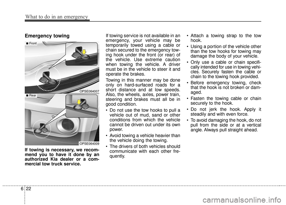
mercial tow truck service. If towing service is not available in an
emergency, your vehicle may be
temporarily towed using a cable or
chain secured to the emergency tow-
ing hook under the front (or rear) of
the vehicle. Use extreme caution
when towing the vehicle. A driver
must be in the vehicle to steer it and
operate the brakes.
Towing in this manner may be done
only on hard-surfaced roads for a
short distance and at low speeds.
Also, the wheels, axles, power train,
steering and brakes must all be in
good condition.
Do not use the tow hooks to pull a
vehicle out of mud, sand or other
conditions from which the vehicle
cannot be driven out under its own
power.
Avoid towing a vehicle heavier than the vehicle doing the towing.
The drivers of both vehicles should communicate with each other fre-
quently. Attach a towing strap to the tow
hook.
Using a portion of the vehicle other than the tow hooks for towing may
damage the body of your vehicle.
Only use a cable or chain specifi- cally intended for use in towing vehi-
cles. Securely fasten the cable or
chain to the towing hook provided.
Before emergency towing, check that the hook is not broken or dam-
aged.
Fasten the towing cable or chain securely to the hook.
Do not jerk the hook. Apply it steadily and with even force.
To avoid damaging the hook, do not pull from the side or at a vertical
angle. Always pull straight ahead.
OPSE064007
OPSE064009
■Front
■Rear
Page 319 of 470
623
What to do in an emergency
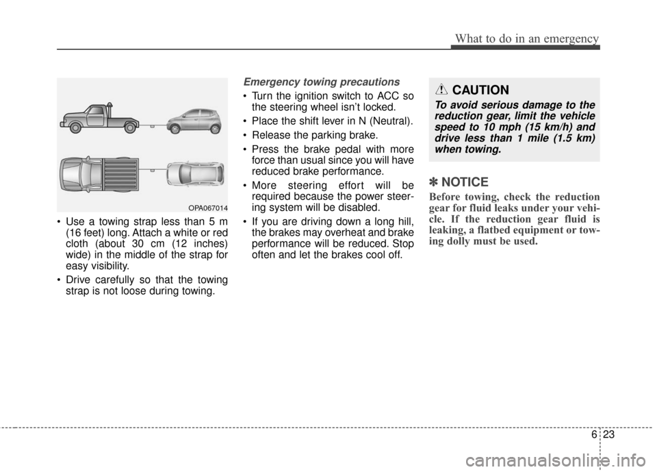
Use a towing strap less than 5 m(16 feet) long. Attach a white or red
cloth (about 30 cm (12 inches)
wide) in the middle of the strap for
easy visibility.
Drive carefully so that the towing strap is not loose during towing.
Emergency towing precautions
Turn the ignition switch to ACC sothe steering wheel isn’t locked.
Place the shift lever in N (Neutral).
Release the parking brake.
Press the brake pedal with more force than usual since you will have
reduced brake performance.
More steering effort will be required because the power steer-
ing system will be disabled.
If you are driving down a long hill, the brakes may overheat and brake
performance will be reduced. Stop
often and let the brakes cool off.
✽ ✽ NOTICE
Before towing, check the reduction
gear for fluid leaks under your vehi-
cle. If the reduction gear fluid is
leaking, a flatbed equipment or tow-
ing dolly must be used.OPA067014
CAUTION
To avoid serious damage to the
reduction gear, limit the vehiclespeed to 10 mph (15 km/h) anddrive less than 1 mile (1.5 km)when towing.
Page 361 of 470
Maintenance
42
7
Traction - AA, A, B & C
The traction grades, from highest to
lowest, are AA, A, B and C. Those
grades represent the tire’s ability to
stop on wet pavement as measured
under controlled conditions on spec-
ified government test surfaces of
asphalt and concrete. A tire marked
C may have poor traction perform-
ance.
The traction grade assigned to this
tire is based on straight-ahead brak-
ing traction tests, and does not
include acceleration, cornering,
hydroplaning, or peak traction char-
acteristics. Temperature -A, B & C
The temperature grades are A (the
highest), B and C representing the
tire’s resistance to the generation of
heat and its ability to dissipate heat
when tested under controlled condi-
tions on a specified indoor laboratory
test wheel.
Sustained high temperature can
cause the material of the tire to
degenerate and reduce tire life, and
excessive temperature can lead to
sudden tire failure. Grades B and A
represent higher levels of perform-
ance on the laboratory test wheel
than the minimum required by law.
Tire terminology and definitions
Air Pressure: The amount of air
inside the tire pressing outward on
the tire. Air pressure is expressed in
pounds per square inch (psi) or kilo-
pascal (kPa).
Accessory Weight: This means the
combined weight of optional acces-
sories. Some examples of optional
accessories are, automatic transaxle,
power seats, and air conditioning.
Aspect Ratio
: The relationship of a
tire's height to its width.
Belt: A rubber coated layer of cords
that is located between the plies and
the tread. Cords may be made from
steel or other reinforcing materials.
Bead: The tire bead contains steel
wires wrapped by steel cords that
hold the tire onto the rim.
Bias Ply Tire : A pneumatic tire in
which the plies are laid at alternate
angles less than 90 degrees to the
centerline of the tread.