Page 383 of 449
747
Maintenance
Reset items
Items should be reset after the battery
has been discharged or the battery has
been disconnected.
Auto down window (See section 4)
Sunroof (See section 4)
Trip computer (See section 4)
Climate control system (See section 4)
Clock (See section 4)
Audio (See section 4)
Page 399 of 449

763
Maintenance
If it fits loosely, consult an authorized Kia
dealer.
If you do not have a spare, use a fuse ofthe same rating from a circuit you maynot need for operating the vehicle, suchas the cigar lighter fuse.
If the headlights or other electrical com-
ponents do not work and the fuses are
OK, check the fuse block in the engine
compartment. If a fuse is blown, it must
be replaced.
Memory fuse
Your vehicle is equipped with the memo-
ry fuse to prevent battery discharge if
your vehicle is parked without being
operated for prolonged periods. Use the
following procedures before parking the
vehicle for prolonged periods.
1. Turn off the engine.
2. Turn off the headlights and tail lights.
3. Open the driver’s side panel cover and pull up the memory fuse. If the memory fuse is pulled up from the
fuse panel, the warning chime, audio,
clock and interior lamps, etc., will not
operate. Some items must be reset after
replacement. Refer to “Battery” in this
section.
Even though the memory fuse is pulled
up, the battery can still be discharged by
operation of the headlights or other elec-
trical devices.
OUB071021
Page 404 of 449

Maintenance
68
7
Instrument panel fuse panel
Fuse Name Fuse rating Circuit Protected
POWER OUTLET 15A Power Outlet
C/LIGHTER 20A Cigarette Lighter
ACC 10AFront Map Lamp, Power Outside Mirror Switch, BCM,
Low DC-DC Convertor, Smart Key Control Module, Audio,
A/V & Navigation Head Unit, Digital Clock
A/BAG IND 10A Instrument Cluster
A/BAG 10ASBR PAB Indicator, SRS Control Module
Passenger Weight Classification Sensor
MODULE 2 10A BCM
MDPS 10A EPS Control Module
WIPER RR 15A Multifunction Switch, Rear Wiper Relay, Rear Wiper Motor
HTD STRG 15A Steering Wheel Heater
FOG LAMP RR 10A -
FOG LAMP FRT 15A Front Fog Lamp Relay
MODULE 1 10A ATM Shift Lever Switch, Door Warning Switch
STOP LAMP 15AData Link Connector, Smart Key Control Module, Stop Lamp Switch
Stop Lamp Relay, PCB Fuse & Relay Box (HAC Relay)
CLUSTER 10AAudio, BCM, ATM Shift Lever ILL., Crash Pad Switch
Instrument Cluster, Tire Pressure Monitoring Module
IG1 1 10AMultipurpose Check Connector, Driver CCS Seat Warmer Module
Passenger Seat Warmer Module
With ISG : Crash Pad Switch, Low DC-DC Convertor
ABS 10ACrash Pad Switch, ESC Module
PCB Fuse & Relay Box (HAC Relay)
B/UP LAMP 10A Back-Up Lamp Switch
Page 405 of 449

769
Maintenance
Fuse Name Fuse ratingCircuit Protected
IG1 2 10AVehicle Speed Sensor, Stop Lamp Switch, Inverter
A/C Control Module
HAZARD 15A Hazard Switch, BCM
PDM 1 25A Smart Key Control Module
SUNROOF 15A Sunroof Motor
PDM 2 10AImmobilizer Module, Start/Stop Button Switch,
Smart Key Control Module
ECU 15ASmart Key Control Module, Immobilizer Module,
ECM/PCM, Transaxle Range Switch
IG2 10ABCM, Smart Key Control Module, Driver CCS Seat Warmer Module
Cluster Ionizer, Rain Sensor, A/C Control Module, Sunroof Motor
PCB Fuse & Relay Box (Blower Relay, Head Lamp (HI) Relay,
Fuel Pump #1 Relay)
WIPER FRT 25AMultifunction Switch, Front Wiper Motor
PCB Fuse & Relay Box (Rain Sensor Relay, Front Wiper Relay)
DOOR LOCK 20ADoor Lock/Unlock Relay, Tail Gate Unlock Relay,
Two Turn Unlock Relay
SAFETY POWER
WINDOW 25A Driver Safety Power Window Module
S/HEATER 15ASeat Warmer Switch, Driver CCS Seat Warmer Module,
Passenger Seat Warmer Module
FOLD'G MIRR 10A Power Outside Mirror Switch
ROOM LP 10ABCM, Door Warning Switch, Tire Pressure Monitoring Module
Instrument Cluster, Digital Clock, A/C Control Module
Luggage Lamp
Page 411 of 449

775
Maintenance
Always handle them carefully, and avoid
scratches and abrasions. If the bulbs are
lit, avoid contact with liquids. Never touch
the glass with bare hands. Residual oil
may cause the bulb to overheat and burst
when lit. A bulb should be operated only
when installed in a headlight.
If a bulb becomes damaged or cracked,
replace it immediately and carefully dis-
pose of it.
Wear eye protection when changing a
bulb. Allow the bulb to cool down before
handling it.1. Turn off the engine and open the hood.
If you can reach the bulb without
removing the headlight assembly, con-
tinue to step 4.
2. Remove the front bumper upper cover.
3. Remove the headlight assembly from the body of the vehicle.
4. Disconnect the power connector(s) from the back of the headlight assem-
bly.
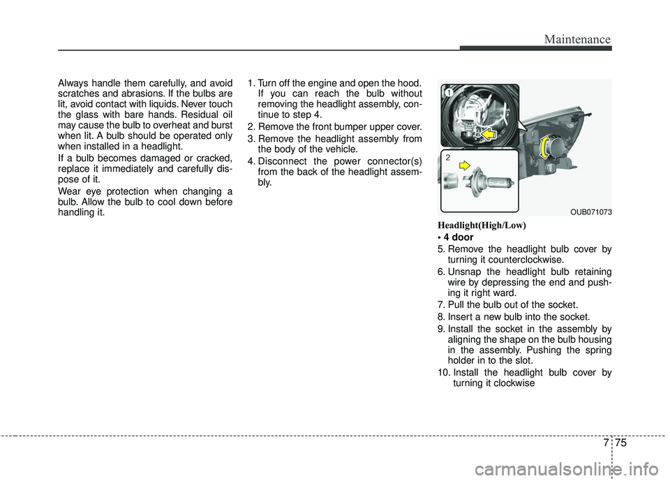
Headlight(High/Low)
5. Remove the headlight bulb cover byturning it counterclockwise.
6. Unsnap the headlight bulb retaining wire by depressing the end and push-
ing it right ward.
7. Pull the bulb out of the socket.
8. Insert a new bulb into the socket.
9. Install the socket in the assembly by aligning the shape on the bulb housing
in the assembly. Pushing the spring
holder in to the slot.
10. Install the headlight bulb cover by turning it clockwise
OUB071073
Page 412 of 449

Maintenance
76
7
Headlight (High)
5. Remove the headlight bulb cover by
turning it counterclockwise.
6. Unsnap the headlight bulb retaining wire by depressing the end and push-
ing it down ward.
7. Pull the bulb out of the socket.
8. Insert a new bulb into the socket.
9. Install the socket in the assembly by aligning the shape on the bulb housing
in the assembly. Pushing the spring
holder in to the slot.
10. Install the headlight bulb cover by turning it clockwise. Headlight (Low)
Follow the steps 1 to 4 from the previous
section.
5. Remove the headlight bulb cover by
turning it counterclockwise.
6. Remove the socket from the assembly by turning the socket counterclockwise
until the tabs on the socket align with
the slots on the assembly.
7. Pull the bulb out of the socket.
8. Insert a new bulb into the socket. 9. Install the socket in the assembly by
aligning the tabs on the socket with the
slots in the assembly. Push the socket
into the assembly and turn the socket
clockwise.
10. Install the headlight bulb cover by turning it clockwise.
If the headlight aiming adjustment is nec-
essary after the headlight assembly is
reinstalled, consult an authorized Kia
dealer.
OUB071030NOUB071029
Page 413 of 449
777
Maintenance
Turn signal light/Position light or Side
marker
Follow the steps 1 to 4 from the previous
page.
5. Remove the socket from the assemblyby turning the socket counterclockwise
until the tabs on the socket align with
the slots on the assembly.
6. Remove the bulb from the socket by pressing it in and rotating it counter-
clockwise until the tabs on the bulb
align with the slots in the socket. Pull
the bulb out of the socket 7. Insert a new bulb by inserting it into
the socket and rotating it until it locks
into place.
8. Install the socket in the assembly by aligning the tabs on the socket with the
slots in the assembly. Push the socket
into the assembly and turn the socket
clockwise.
Position light (if equipped)
If the light bulb does not operate, have
the vehicle checked by an authorized Kia
dealer.
OUB071031N
OUB071055
OUB071077
OUB071056
■ 4 door
■ 5 door
Page 414 of 449

Maintenance
78
7
Front fog light bulbs (if equipped)
1. Remove the under cover by rotating
the screws.
2. Reach your hand into the back of the front bumper.
3. Disconnect the power connector from the socket.
4. Remove the bulb-socket from the housing by turning the socket counter
clockwise until the tabs on the socket
align with the slots on the housing.
5. Install the new bulb-socket into the housing by aligning the tabs on the
socket with the slots in the housing.
Push the socket into the housing and
turn the socket clockwise.
6 Connect the power connector to the socket.
Side repeater light bulb replace-
ment (if equipped)
Type A
If the light bulb does not operate,have the
vehicle checked by an authorized Kia
dealer. A skilled technician should check
or repair the side repeater lamp, for it
may damage related out side mirror parts
of the vehicle.
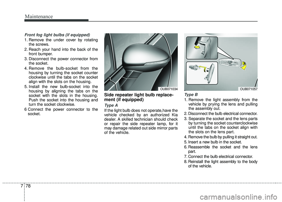
Type B
1. Remove the light assembly from the vehicle by prying the lens and pulling
the assembly out.
2. Disconnect the bulb electrical connector.
3. Separate the socket and the lens parts by turning the socket counterclockwise
until the tabs on the socket align with
the slots on the lens part.
4. Remove the bulb by pulling it straight out.
5. Insert a new bulb in the socket.
6. Reassemble the socket and the lens part.
7. Connect the bulb electrical connector.
8. Reinstall the light assembly to the body of the vehicle.
OUB071034OUB071057