Page 116 of 449

445
Features of your vehicle
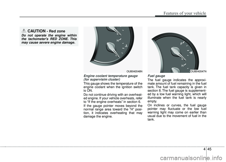
Engine coolant temperature gauge(for supervisim cluster)
This gauge shows the temperature of the
engine coolant when the ignition switch
is ON.
Do not continue driving with an overheat-
ed engine. If your vehicle overheats, refer
to “If the engine overheats” in section 6.
If the gauge pointer moves beyond the
normal range area toward the “H” posi-
tion, it indicates overheating that may
damage the engine.
Fuel gauge
The fuel gauge indicates the approxi-
mate amount of fuel remaining in the fuel
tank. The fuel tank capacity is given in
section 8. The fuel gauge is supplement-
ed by a low fuel warning light, which will
illuminate when the fuel tank is nearly
empty.
On inclines or curves, the fuel gauge
pointer may fluctuate or the low fuel
warning light may come on earlier than
usual due to the movement of fuel in the
tank.
OUB042048N
CAUTION - Red zone
Do not operate the engine withinthe tachometer's RED ZONE. Thismay cause severe engine damage.
OUB042047N
Page 129 of 449

Features of your vehicle
58
4
The oil pressure warning light comes on
whenever there is insufficient oil pres-
sure. In normal operation, it should come
on when the ignition switch is turned on,
then go out when the engine is started. If
the oil pressure warning light stays on
while the engine is running, there is a
serious malfunction.Parking brake & brake
fluid warning light
Parking brake warning
This warning light illuminates for 3 sec-
onds after the ignition switch is turned to
the ON position and then it will go out.
Also, this light illuminates when the park-
ing brake is applied with the ignition
switch in the START or ON position. The
warning light should go out when the
parking brake is released. Low brake fluid level warning
If the warning light remains on, it may
indicate that the brake fluid level in the
reservoir is low.
If the warning light remains on:
1. Drive carefully to the nearest safe
location and stop your vehicle.
2. With the engine stopped, check the brake fluid level immediately and add
fluid as required. Then check all brake
components for fluid leaks.
3. Do not drive the vehicle if leaks are found, the warning light remains on or
the brakes do not operate properly.
Have the vehicle towed to any author-
ized Kia dealer for a brake system
inspection and necessary repairs.
Page 146 of 449
475
Features of your vehicle
High beam operation
To turn on the high beam headlights,
push the lever away from you. Pull it back
for low beams.
The high-beam indicator will light when
the headlight high beams are switched
on.
To prevent the battery from being dis-
charged, do not leave the lights on for a
prolonged time while the engine is not
running.To flash the headlights, pull the lever
towards you. It will return to the normal
(low-beam) position when released. The
headlight switch does not need to be on
to use this flashing feature.
OAM049044
WARNING- High beams
Do not use high beam when there
are other vehicles. Using high
beam could obstruct the other dri-
ver's vision.
OAM049043
Page 150 of 449

479
Features of your vehicle
Windshield washers
In the OFF position, pull the lever gently
toward you to spray washer fluid on the
windshield and to run the wipers 1-3
cycles.
Use this function when the windshield is
dirty.
The spray and wiper operation will con-
tinue until you release the lever. If the
washer does not work, check the washer
fluid level.
If the fluid level is not sufficient, you will
need to add appropriate non-abrasive
windshield washer fluid to the washer
reservoir.
The reservoir filler neck is located in the
front of the engine compartment on the
passenger side.CAUTION - Washer pump
To prevent possible damage to thewasher pump, do not operate thewasher when the fluid reservoir is empty.
WARNING- Obscured visibility
Do not use the washer in freezing
temperatures without first warming
the windshield with the defrosters;
the washer solution could freeze on
the windshield and obscure your
vision.
CAUTION - Wiper position
When washing the vehicle, set the
wiper switch in the off position tostop the auto wiper operation.
The wiper may operate and be dam-aged if the switch is set in the AUTOmode while washing the vehicle.
Page 157 of 449

Features of your vehicle
86
4
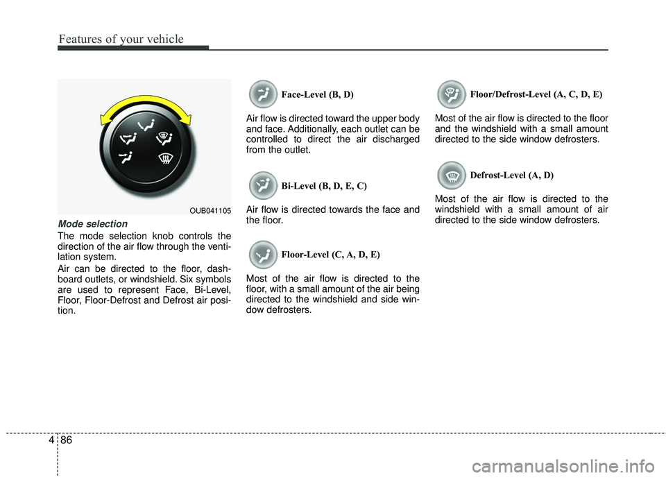
Mode selection
The mode selection knob controls the
direction of the air flow through the venti-
lation system.
Air can be directed to the floor, dash-
board outlets, or windshield. Six symbols
are used to represent Face, Bi-Level,
Floor, Floor-Defrost and Defrost air posi-
tion. Face-Level (B, D)
Air flow is directed toward the upper body
and face. Additionally, each outlet can be
controlled to direct the air discharged
from the outlet.
Bi-Level (B, D, E, C)
Air flow is directed towards the face and
the floor.
Floor-Level (C, A, D, E)
Most of the air flow is directed to the
floor, with a small amount of the air being
directed to the windshield and side win-
dow defrosters. Floor/Defrost-Level (A, C, D, E)
Most of the air flow is directed to the floor
and the windshield with a small amount
directed to the side window defrosters.
Defrost-Level (A, D)
Most of the air flow is directed to the
windshield with a small amount of air
directed to the side window defrosters.
OUB041105
Page 168 of 449
497
Features of your vehicle
Mode selection
The mode selection button controls the
direction of the air flow through the venti-
lation system.
The air flow outlet port is converted as
follows:
Refer to the illustration in the “Manual cli-
mate control system”.Floor & Defrost (A, C, D, E)
Most of the air flow is directed to the floor
and the windshield with a small amount
directed to the side window defrosters.
Face-Level (B, D)
Air flow is directed toward the upper body
and face. Additionally, each outlet can be
controlled to direct the air discharged
from the outlet. Bi-Level (B, D, C, E)
Air flow is directed towards the face and
the floor.
Floor-Level (C, A, D, E)
Most of the air flow is directed to the
floor, with a small amount of the air being
directed to the windshield and side win-
dow defrosters.
OUB045123
Page 180 of 449

4109
Features of your vehicle
This indicator illuminates
when the auto defogging
system senses the moisture
of inside the windshield and
operates.
If more moisture is in the vehicle, higher
steps operate as follow.
Step 1 : Operating the air conditioning
Step 2 : Outside air position
Step 3 : Blowing air flow toward the wind- shield
Step 4 : Increasing air flow toward the windshield If your vehicle is equipped with the auto
defogging system, it is automatically acti-
vated when the conditions are met.
However, if you would like to cancel the
auto defogging system, press the front
defroster button 4 times within 2 seconds
while pressing the AUTO button. The
indicator will blink 3 times to notify you
that the system is cancelled. To use the
auto defogging system again, follow the
procedures mentioned above.
If the battery has been disconnected or
discharged, it resets to the auto defog-
ging status.
✽ ✽
NOTICE
If the A/C off is manually selected while
the auto defogging system is on, the auto
defogging indicator will blink 3 times to
give notice that the A/C off can not be
selected.
CAUTION
Do not remove the sensor cover
located on the upper end of thedriver side windshield glass. Damage to the system parts couldoccur and may not be covered byyour vehicle warranty.
Page 194 of 449

Features of your vehicle
4123
Aux, USB and iPod®
(if equipped)
If your vehicle has an AUX and/or USB
(universal serial bus) port, you can use
an AUX port to connect audio devices
and an USB port to plug in an USB and
also plug in an iPod
®.
iPod®mobile digital device sold sepa-
rately. Connectivity may require use of
the Kia accessory cable.
When using a portable audio device con-
nected to the power outlet, noise may
occur during playback. If this happens,
use the power source of the portable
audio device.
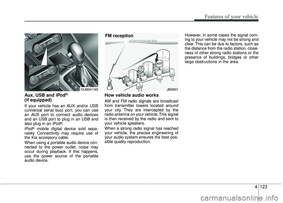
How vehicle audio works
AM and FM radio signals are broadcast
from transmitter towers located around
your city. They are intercepted by the
radio antenna on your vehicle. This signal
is then received by the radio and sent to
your vehicle speakers.
When a strong radio signal has reached
your vehicle, the precise engineering of
your audio system ensures the best pos-
sible quality reproduction. However, in some cases the signal com-
ing to your vehicle may not be strong and
clear. This can be due to factors, such as
the distance from the radio station, close-
ness of other strong radio stations or the
presence of buildings, bridges or other
large obstructions in the area.
JBM001
FM reception
OUB041165