Page 621 of 723

Maintenance
34
8
ENGINE COOLANT
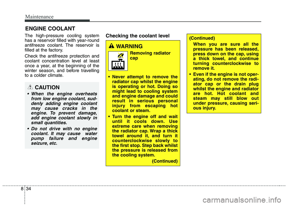
The high-pressure cooling system
has a reservoir filled with year-round
antifreeze coolant. The reservoir is
filled at the factory.
Check the antifreeze protection and
coolant concentration level at least
once a year, at the beginning of the
winter season, and before travelling
to a colder climate. Checking the coolant level
(Continued)
When you are sure all the pressure has been released,
press down on the cap, using
a thick towel, and continue
turning counterclockwise to
remove it.
Even if the engine is not oper- ating, do not remove the radi-ator cap or the drain plugwhilst the engine and radiator
are hot. Hot coolant and
steam may still blow out
under pressure, causing seri-
ous injury.
WARNING
Removing radiatorcap
Never attempt to remove the radiator cap whilst the engine
is operating or hot. Doing somight lead to cooling system
and engine damage and could
result in serious personal
injury from escaping hotcoolant or steam.
Turn the engine off and wait until it cools down. Use
extreme care when removing
the radiator cap. Wrap a thick
towel around it, and turn it
counterclockwise slowly to
the first stop. Step back whilst
the pressure is released fromthe cooling system.
(Continued)
CAUTION
When the engine overheatsfrom low engine coolant, sud-denly adding engine coolantmay cause cracks in theengine. To prevent damage, add engine coolant slowly insmall quantities.
Do not drive with no engine coolant. It may cause waterpump failure and engine seizure, etc.
Page 622 of 723

835
Maintenance
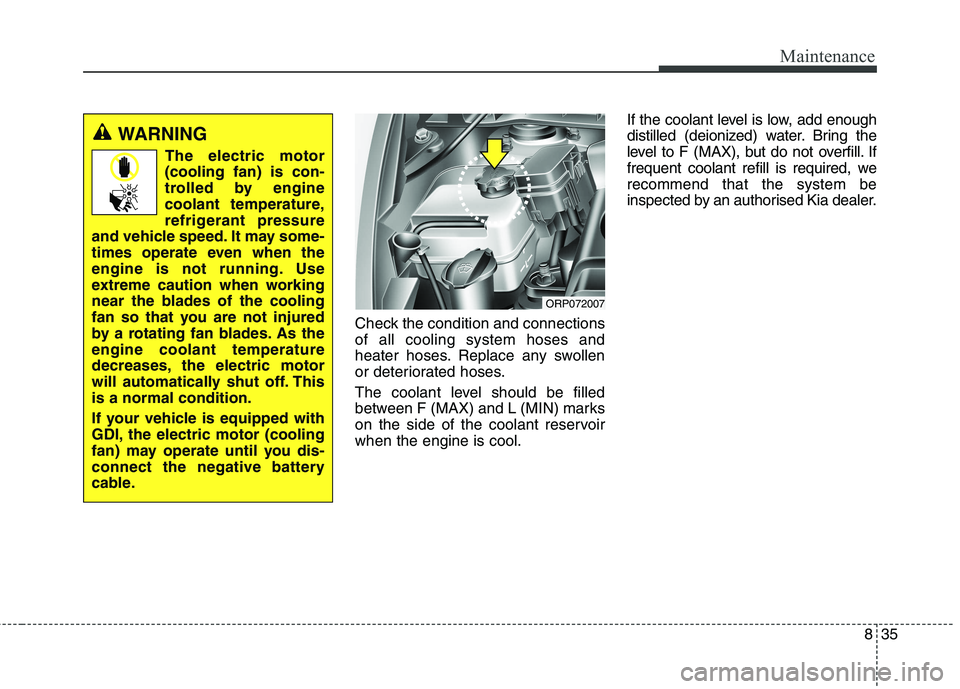
Check the condition and connections of all cooling system hoses and
heater hoses. Replace any swollen
or deteriorated hoses.
The coolant level should be filled
between F (MAX) and L (MIN) marks
on the side of the coolant reservoirwhen the engine is cool.If the coolant level is low, add enough
distilled (deionized) water. Bring the
level to F (MAX), but do not overfill. If
frequent coolant refill is required, werecommend that the system be
inspected by an authorised Kia dealer.
WARNING
The electric motor
(cooling fan) is con-
trolled by engine
coolant temperature,
refrigerant pressure
and vehicle speed. It may some-
times operate even when the
engine is not running. Use
extreme caution when working
near the blades of the cooling
fan so that you are not injured
by a rotating fan blades. As theengine coolant temperature
decreases, the electric motor
will automatically shut off. Thisis a normal condition.
If your vehicle is equipped with
GDI, the electric motor (cooling
fan) may operate until you dis-
connect the negative battery
cable.
ORP072007
Page 625 of 723

Maintenance
38
8
BRAKE/CLUTCH FLUID (IF EQUIPPED)
Checking the brake/clutch
fluid level
Check the fluid level in the reservoir
periodically. The fluid level should be
between MAX and MIN marks on the
side of the reservoir.
Before removing the reservoir cap
and adding brake/clutch fluid, clean
the area around the reservoir cap
thoroughly to prevent brake/clutchfluid contamination.
If the level is low, add fluid to the
MAX level. The level will fall with
accumulated mileage. This is a nor-mal condition associated with the
wear of the brake linings. If the fluid level is excessively low, werecommend that the system be
checked by an authorised Kia dealer.
Use only the specified brake fluid.
(Refer to “Recommended lubricantsand capacities” in chapter 9.)
Never mix different types of fluid.
ORP076084R
WARNING - Brake /
clutch fluid
When changing and adding
brake/clutch fluid, handle it
carefully. Do not let it come in
contact with your eyes. If
brake/clutch fluid should come
in contact with your eyes, imme-
diately flush them with a large
quantity of fresh tap water. Have
your eyes examined by a doctor
as soon as possible.
WARNING - Loss of
brake/clutch fluid
In the event the brake/clutch
system requires frequent addi-
tions of fluid, we recommend
that the system be inspected by
an authorised Kia dealer.
CAUTION
Do not allow brake/clutch fluid to contact the vehicle's bodypaint, as paint damage will result. Brake/clutch fluid, whichhas been exposed to open airfor an extended time should never be used as its quality can-not be guaranteed. It should beproperly disposed. Don't put in the wrong kind of fluid. A fewdrops of mineral-based oil, suchas engine oil, in your brake/ clutch system can damagebrake/clutch system parts.
Page 638 of 723

851
Maintenance
Reset items Items should be reset after the bat-
tery has been discharged or the bat-
tery has been disconnected.
Auto up/down window (See chapter 4)
Sunroof (See chapter 4)
Trip computer (See chapter 4)
Climate control system (See chapter 4)
Audio (See chapter 5)(Continued)
Disconnect the battery charg- er in the following order.
1. Turn off the battery charger main switch.
2. Unhook the negative clamp from the negative battery terminal.
3. Unhook the positive clamp from the positive batteryterminal.
Before performing mainte- nance or recharging the bat-
tery, turn off all accessories
and stop the engine.
The negative battery cable must be removed first and
installed last when the batteryis disconnected.WARNING - Recharging
battery
When recharging the battery,
observe the following precau-tions:
The battery must be removed from the vehicle and placed in an area with good ventilation.
Do not allow cigarettes, sparks, or flame near the bat-
tery.
Watch the battery during charging, and stop or reduce
the charging rate if the batterycells begin gassing (boiling)
violently or if the temperature
of the electrolyte of any cell
exceeds 49°C (120°F).
Wear eye protection when checking the battery during
charging.
(Continued)
Page 650 of 723

863
Maintenance
FUSESA vehicle’s electrical system is pro-
tected from electrical overload dam-
age by fuses.
This vehicle has 3 (or 4) fuse panels,
one located in the driver’s side panel
bolster, others in the engine com-
partment near the battery.
If any of your vehicle’s lights, acces-
sories, or controls do not work, check
the appropriate circuit fuse. If a fuse
has blown, the element inside thefuse will be melted.
If the electrical system does not
work, first check the driver’s sidefuse panel.
Always replace a blown fuse with
one of the same rating.
Before replacing a blown fuse, dis-
connect the negative battery cable.
If the replacement fuse blows, this
indicates an electrical problem. Avoid
using the system involved and we
recommend that you consult an
authorised Kia dealer.
Three kinds of fuses are used: bladetype for lower amperage rating, car-tridge type, and multi fuse type for higher amperage ratings.
WARNING - Fuse
replacement
Never replace a fuse with any- thing but another fuse of the same rating.
A higher capacity fuse could cause damage and possibly a
fire.
Never install a wire or aluminum foil instead of the proper fuse -
even as a temporary repair. It
may cause extensive wiring
damage and a possible fire.
Do not arbitrarily modify or add-on electric wiring of the
vehicle.
Normal
Normal
■
Blade type
■ Cartridge type
■ Multi fuse type Blown
Blown
Normal Blown
ORB072110/ODM072020
Normal
Blown
■
Battery fuse terminal
Page 652 of 723
865
Maintenance
Inner panel fuse replacement
1. Turn the ignition switch and allother switches off.
2. Open the fuse panel cover. 3. Pull the suspected fuse straight
out. Use the removal tool provided
in the engine compartment fusepanel.
4. Check the removed fuse; replace it if it is blown.
5. Push in a new fuse of the same rating, and make sure it fits tightly
in the clips.
If it fits loosely, we recommend that
you consult an authorised Kia dealer.
If you do not have a spare, use a fuse of the same rating from a circuityou may not need for operating the vehicle, such as the cigar lighterfuse. If the headlights, fog lights, turn sig-
nal lights, position lights or interior lights do not work and there is noth-ing wrong with the bulbs, we recom-mend that you consult with an autho- rised Kia dealer.
ORP072014R
ORP072015
Page 654 of 723

867
Maintenance
2. Remove the fuse panel cover bypressing the tab and pulling the
cover up. When the blade type
fuse is disconnected, remove it by
using the clip designed for chang-ing fuses located in the engine
room fuse box. Upon removal,
securely insert reserve fuse of
equal quantity.
3. Check the removed fuse; replace it if it is blown. To remove or insert
the fuse, use the fuse puller in the
engine compartment fuse panel.
4. Push in a new fuse of the same rat- ing, and make sure it fits tightly in
the clips. If it fits loosely, we recom-
mend that you consult an autho-
rised Kia dealer.Main fuse
If the main fuse is blown, it must be
removed as follows:
1. Turn off the engine.
2. Disconnect the negative battery cable.
3. Remove the nuts shown in the pic- ture above.
4. Replace the fuse with a new one of the same rating.
5. Reinstall in the reverse order of removal.
OGDE071020R
CAUTION
After checking the fuse box in the
engine compartment, securelyinstall the fuse box cover. If not, electrical failures may occur fromwater leaking in.
CAUTION
Visually inspect the battery capfor secure closing. If the batterycap is not securely latched, the electrical system may be dam-aged to due influx of moistureinto the system.
Page 663 of 723

Maintenance
76
8
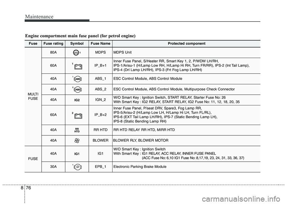
Engine compartment main fuse panel (for petrol engine)
Fuse Fuse ratingSymbolFuse NameProtected component
MULTI
FUSE
80A1MDPSMDPS Unit
60A1IP_B+1Inner Fuse Panel, S/Heater RR, Smart Key 1, 2, P/WDW LH/RH,
IPS-1/Arisu-1 (H/Lamp Low RH, H/Lamp Hi RH, Turn FR/RR), IPS-2 (Int Tail Lamp),
IPS-4 (Drl Lamp LH/RH), IPS-3 (Frt Fog Lamp LH/RH)
40A1ABS_1ESC Control Module, ABS Control Module
40A2ABS_2ESC Control Module, ABS Control Module, Multipurpose Check Connector
40AIG2IGN_2W/O Smart Key : Ignition Switch, START RELAY, Starter Fuse No: 26
With Smart Key : IG2 RELAY, START RELAY, IG2 Fuse No: 11, 12, 18, 20, 35
60A2IP_B+2
Inner Fuse Panel, P/seat DRV, Spare3, Fog Lamp RR,
IPS-5/Arisu-2 (H/Lamp Low LH, H/Lamp Hi LH, Turn FL/RL),
IPS-6 (EXT Tail Lamp LH/RH), IPS-7 (Static Bending Lamp LH), IPS-8 (Static Bending Lamp RH)
40ARR
HTDRR HTDRR HTD RELAY RR HTD, MIRR HTD
40ABLOWERBLOWER RLY, BLOWER MOTOR
FUSE
40AIG1IG1W/O Smart Key : Ignition Switch
With Smart Key : IG1 RELAY, ACC RELAY, INNER FUSE PANEL
(ACC Fuse No: 6,10 IG1 Fuse No: 8,17,19, 23, 24, 31, 33, 36, 37)
30A1EPB_1Electronic Parking Brake Module