Page 210 of 372
Rear Liftgate Mounted Tail Lamp
1. Raise the liftgate.
2. Use a suitable tool to pry the lower trimfrom the liftgate. 3. Continue removing the trim.
4. Disconnect the two trim panel lights.
5. Tail lamps are now visible. Rotate sock-
et(s) counter clockwise.
6. Remove/replace bulb(s).
7. Reinstall the socket(s).
8. Reverse process to reinstall the liftgatetrim.
Rear Liftgate Tail Lamps
Liftgate Lower Trim
Rear Of Liftgate Tail Lamp
1 — Auxiliary LED Tail Connector – Do
Not Remove
2 — Backup Bulb Socket
IN CASE OF EMERGENCY
208
Page 212 of 372
CavityCartridge Fuse Micro Fuse Description
F03 60 Amp Yellow – Radiator Fan
F05 40 Amp Green –Compressor for Air Suspension — If Equipped
F06 40 Amp Green –Anti-lock Brakes/Electronic Stability Control Pump
F07 30 Amp Pink – Starter Solenoid
F09 30 Amp Pink –Diesel Fuel Heater (Diesel engine only)/Brake Vacuum
Pump
F10 40 Amp Green –Body Controller/Exterior Lighting #2
Power Distribution Center
Power Distribution Center
IN CASE OF EMERGENCY
210
Page 213 of 372

CavityCartridge Fuse Micro Fuse Description
F11 30 Amp Pink –Trailer Tow Electric Brake — If Equipped
F12 40 Amp Green –Body Controller #3/Power Locks
F13 40 Amp Green –Blower Motor Front
F14 40 Amp Green –Body Controller #4/Exterior Lighting #1
F17 30 Amp Pink –Headlamp Washer — If Equipped
F19 20 Amp Blue –Headrest Solenoid — If Equipped
F20 30 Amp Pink –Passenger Door Module
F22 20 Amp Blue –Engine Control Module
F23 30 Amp Pink – Interior Lights #1
F24 30 Amp Pink –Driver Door Module
F25 30 Amp Pink – Front Wipers
F26 30 Amp Pink –Anti-lock Brakes/Stability Control Module/Valves
F28 20 Amp Blue –Trailer Tow Backup Lights — If Equipped
F29 20 Amp Blue –Trailer Tow Parking Lights — If Equipped
F30 30 Amp Pink –Trailer Tow Receptacle — If Equipped
F32 30 Amp Pink –Drive Train Control Module
F34 30 Amp Pink –Slip Differential Control
F35 30 Amp Pink –Sunroof - If Equipped
F36 30 Amp Pink – Rear Defroster
F37 25 Amp Clear –Rear Blower Motor — If Equipped
F38 30 Amp Pink –Power Inverter 115V AC — If Equipped
F39 30 Amp Pink –Power Liftgate — If Equipped
F40 –10 Amp Red Daytime Running Lights/Headlamp Leveling
211
Page 214 of 372

CavityCartridge Fuse Micro Fuse Description
F42 –20 Amp Yellow Horn
F44 –10 Amp Red Diagnostic Port
F49 –10 Amp Red Integrated Central Stack/Climate Control
F50 –20 Amp Yellow Air Suspension Control Module - If Equipped
F51 –15 Amp Blue Ignition Node Module/Keyless Ignition/Steering Column
Lock
F52 –5 Amp Tan Battery Sensor
F53 –20 Amp Yellow Trailer Tow – Left Turn/Stop Lights — If Equipped
F56 –15 Amp Blue Additional Content (Diesel engine only)
F57 –20 Amp Yellow NOX Sensor
F58 –15 Amp Blue HID Headlamps LH — If Equipped
F59 –10 Amp Red Purging Pump (Diesel engine only)
F60 –15 Amp Blue Transmission Control Module
F61 –10 Amp Red Transmission Control Module/PM Sensor (Diesel engine
only)
F62 –10 Amp Red Air Conditioning Clutch
F63 –20 Amp Yellow Ignition Coils (Gas), Urea Heater (Diesel)
F64 –25 Amp Clear Fuel Injectors/Powertrain
F66 –10 Amp Red Sunroof/Passenger Window Switches/Rain Sensor
F67 –15 Amp Blue CD/DVD/Bluetooth Hands-free Module — If Equipped
F68 –20 Amp Yellow Rear Wiper Motor
F69 –15 Amp Blue Spotlight Feed — If Equipped
F70 –20 Amp Yellow Fuel Pump Motor
IN CASE OF EMERGENCY
212
Page 215 of 372

CavityCartridge Fuse Micro Fuse Description
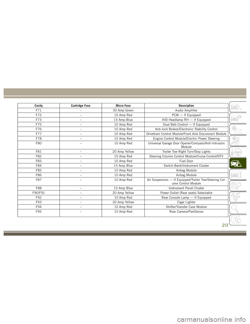
F71 –30 Amp Green Audio Amplifier
F72 –10 Amp Red PCM — If Equipped
F73 –15 Amp Blue HID Headlamp RH — If Equipped
F75 –10 Amp Red Dual Batt Control — If Equipped
F76 –10 Amp Red Anti-lock Brakes/Electronic Stability Control
F77 –10 Amp Red Drivetrain Control Module/Front Axle Disconnect Module
F78 –10 Amp Red Engine Control Module/Electric Power Steering
F80 –10 Amp Red Universal Garage Door Opener/Compass/Anti-Intrusion
Module
F81 –20 Amp Yellow Trailer Tow Right Turn/Stop Lights
F82 –10 Amp Red Steering Column Control Module/Cruise Control/DTV
F83 –10 Amp Red Fuel Door
F84 –15 Amp Blue Switch Bank/Instrument Cluster
F85 –10 Amp Red Airbag Module
F86 –10 Amp Red Airbag Module
F87 –10 Amp Red Air Suspension — If Equipped/Trailer Tow/Steering Col-
umn Control Module
F88 –15 Amp Blue Instrument Panel Cluster
F90/F91 –20 Amp Yellow Power Outlet (Rear seats) Selectable
F92 –10 Amp Red Rear Console Lamp — If Equipped
F93 –20 Amp Yellow Cigar Lighter
F94 –10 Amp Red Shifter/Transfer Case Module
F95 –10 Amp Red Rear Camera/ParkSense
213
Page 218 of 372
WARNING!
Do not attempt to change a tire on the side
of the vehicle closest to moving traffic,
pull far enough off the road to avoid being
hit when operating the jack or changing
the wheel.
2. Turn on the Hazard Warning flasher.
3. Set the parking brake.
4. Place the gear selector into PARK.
5. Turn the ignition OFF.
6. Block both the front and rear of the wheel
diagonally opposite of the jacking posi-
tion. For example, if changing the right
front tire, block the left rear wheel.NOTE:
Passengers should not remain in the ve-
hicle when the vehicle is being jacked.
7. For vehicles equipped with Quadra-Lift, refer to “Quadra-Lift — If Equipped” in
“Starting And Operating” in the Owners
Manual at
www.jeep.com/en/owners/manuals/ for
further information on disabling auto-
matic leveling.
Wheel Blocked
IN CASE OF EMERGENCY
216
Page 221 of 372

5. For a rear tire, place the jack in the slot onthe rear tie-down bracket, just forward of
the rear tire (as indicated by the triangular
lift point symbol on the sill molding). Do
not raise the vehicle until you are sure the
jack is fully engaged. 6. Raise the vehicle by turning the jack
screw clockwise. Raise the vehicle only
until the tire just clears the surface and
enough clearance is obtained to install
the spare tire. Minimum tire lift provides
maximum stability.
WARNING!
Raising the vehicle higher than necessary
can make the vehicle less stable. It could
WARNING!
slip off the jack and hurt someone near it.
Raise the vehicle only enough to remove
the tire.
7. Remove the lug nuts and wheel.
8. Position the spare wheel/tire on the ve- hicle and install the lug nuts with the
cone-shaped end toward the wheel.
Lightly tighten the nuts.
WARNING!
To avoid the risk of forcing the vehicle off
the jack, do not tighten the lug nuts fully
until the vehicle has been lowered. Failure
to follow this warning may result in serious
injury.Front Jacking LocationRear Jacking Location
219
Page 222 of 372

CAUTION!
Be sure to mount the spare tire with the
valve stem facing outward. The vehicle
could be damaged if the spare tire is
mounted incorrectly.
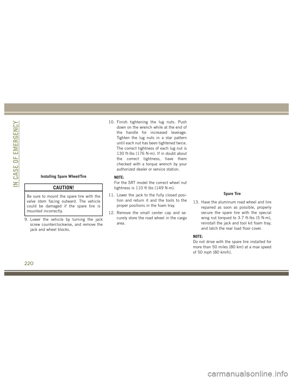
9. Lower the vehicle by turning the jack screw counterclockwise, and remove the
jack and wheel blocks. 10. Finish tightening the lug nuts. Push
down on the wrench while at the end of
the handle for increased leverage.
Tighten the lug nuts in a star pattern
until each nut has been tightened twice.
The correct tightness of each lug nut is
130 ft-lbs (176 N·m). If in doubt about
the correct tightness, have them
checked with a torque wrench by your
authorized dealer or service station.
NOTE:
For the SRT model the correct wheel nut
tightness is 110 ft lbs (149 N·m).
11. Lower the jack to the fully closed posi- tion and return it and the tools to the
proper positions in the foam tray.
12. Remove the small center cap and se- curely store the road wheel in the cargo
area. 13. Have the aluminum road wheel and tire
repaired as soon as possible, properly
secure the spare tire with the special
wing nut torqued to 3.7 ft-lbs (5 N·m),
reinstall the jack and tool kit foam tray,
and latch the rear load floor cover.
NOTE:
Do not drive with the spare tire installed for
more than 50 miles (80 km) at a max speed
of 50 mph (80 km/h).
Installing Spare Wheel/Tire
Spare Tire
IN CASE OF EMERGENCY
220