2017 Hyundai Sonata battery
[x] Cancel search: batteryPage 473 of 563

7-28
Maintenance
The electric motor for the cooling fan
is controlled by engine coolant tem-
perature, refrigerant pressure and
vehicle speed. As the engine coolant
temperature decreases, the electric
motor will automatically shut off. This
is a normal condition. If your vehicle
is equipped with GDI, the electric
motor for the cooling fan may begin
to operate at any time and continue
to operate until you disconnect the
negative battery cable. Check the condition and connections
of all cooling system hoses and
heater hoses. Replace any swollen
or deteriorated hoses.
The coolant level should be filled
between the F and the L marks on
the side of the coolant reservoir
when the engine is cool.
If the coolant level is low, add enough
distilled (deionized) water to bring
the level to the F mark, but do not
overfill. If frequent additions are
required, we recommend that you
see an authorized HYUNDAI dealer
for a cooling system inspection.
Recommended engine coolant
When adding coolant, use only
deionized water, distilled water or
soft water for your vehicle and
never mix hard water in the coolant
filled at the factory.
An improper coolant mixture can result in severe malfunction or
engine damage.
The engine in your vehicle has alu- minum engine parts and must be
protected by an ethylene-glycol
with phosphate based coolant to
prevent corrosion and freezing.
Do not use alcohol or methanol coolant or mix them with the spec-
ified coolant.
Do not use a solution that contains more than 60% antifreeze or less
than 35% antifreeze, which would
reduce the effectiveness of the
solution.
The electric motor for
the cooling fan may
continue to operate
or start up when the
engine is not running
and can cause serious injury.
Keep hands, clothing and tools
away from the rotating fan
blades of the cooling fan.WARNING
OLF074006N
Page 483 of 563

7-38
Maintenance
B
BA
A T
TT
TE
ER
R Y
Y
To prevent SERIOUS INJURY or
DEATH to you or bystanders,
always follow these precautions
when working near or handling
the battery:
Always read and follow
instructions carefully
when handling a battery.Wear eye protection
designed to protect the
eyes from acid splashes.
Keep all flames, sparks,
or smoking materials
away from the battery.
Hydrogen is always pres- ent in battery cells, is
highly combustible, and
may explode if ignited.
Keep batteries out of
reach of children.
(Continued)
WARNING (Continued)Batteries contain sulfu-
ric acid which is highly
corrosive. Do not allow
acid to contact your
eyes, skin or clothing.
If acid gets into your eyes, flush
your eyes with clean water for at
least 15 minutes and get imme-
diate medical attention. If acid
gets on your skin, thoroughly
wash the area. If you feel pain or
a burning sensation, get med-
ical attention immediately.
When lifting a plastic-cased
battery, excessive pressure
on the case may cause battery
acid to leak. Lift with a battery
carrier or with your hands on
opposite corners.
Do not attempt to jump start
your vehicle if your battery is
frozen. (Continued)
(Continued)
NEVER attempt to recharge
the battery when the vehicle’s
battery cables are connected
to the battery.
The electrical ignition system
works with high voltage.
NEVER touch these compo-
nents with the engine running
or when the ignition is in the
ON position.
Page 484 of 563

7-39
7
Maintenance
When you do not use the vehiclefor a long time in a low tempera-
ture area, disconnect the battery
and keep it indoors.
Always charge the battery fully to prevent battery case damage
in low temperature areas.
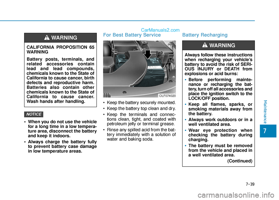
For Best Battery Service
Keep the battery securely mounted.
Keep the battery top clean and dry.
Keep the terminals and connec-tions clean, tight, and coated with
petroleum jelly or terminal grease.
Rinse any spilled acid from the bat- tery immediately with a solution of
water and baking soda.
Battery Recharging
NOTICE
CALIFORNIA PROPOSITION 65
WARNING
Battery posts, terminals, and
related accessories contain
lead and lead compounds,
chemicals known to the State of
California to cause cancer, birth
defects and reproductive harm.
Batteries also contain other
chemicals known to the State of
California to cause cancer.
Wash hands after handling.
WARNING
OLF074020
Always follow these instructions
when recharging your vehicle’s
battery to avoid the risk of SERI-
OUS INJURY or DEATH from
explosions or acid burns:
Before performing mainte-
nance or recharging the bat-
tery, turn off all accessories and
place the ignition switch to the
LOCK/OFF position.
Keep all flames, sparks, or
smoking materials away from
the battery.
Always work outdoors or in a
well ventilated area.
Wear eye protection when
checking the battery during
charging.
The battery must be removed
from the vehicle and placed in
a well ventilated area.
(Continued)
WARNING
Page 485 of 563

7-40
Maintenance
By jump starting
After a jump start from a good bat-
tery, idle the vehicle with the head-
lights turned ON for 20-30 minutes
before started driving. The vehicle
may not run properly if you drive it off
before the battery had a chance to
adequately recharge. See "Jump
Starting" in chapter 6 for more infor-
mation on jump starting procedures.
Information
An inappropriately disposedbattery can be harmful to
the environment and human
health.
Dispose the battery according to your
local law(s) or regulation.
Reset features
Some items need to be reset after
the battery has been discharged or
the battery has been disconnected.
See chapter 3 for:
Power Windows
Trip Computer
Climate Control System
Clock
Audio System
Sunroof
i
(Continued)
Watch the battery during
charging, and stop or reduce
the charging rate if the battery
cells begin boiling violently.
The negative battery cable
must be removed first and
installed last when the battery
is disconnected. Disconnect
the battery charger in the fol-
lowing order:
(1) Turn off the battery charger main switch.
(2) Unhook the negative
clamp from the negative
battery terminal.
(3) Unhook the positive clamp from the positive battery
terminal.
Always use a genuine HYUNDAI
approved battery when you
replace the battery.
Page 498 of 563

7-53
7
Maintenance
Pneumatic tire
A mechanical device made of rubber,
chemicals, fabric and steel or other
materials, that, when mounted on an
automotive wheel provides the trac-
tion and contains the gas or fluid that
sustains the load.
Pneumatic options weight
The combined weight of installed
regular production options weighing
over 5lb. (2.3kg) in excess of the
standard items which they replace,
not previously considered in curb
weight or accessory weight, includ-
ing heavy duty breaks, ride levelers,
roof rack, heavy duty battery, and
special trim.
Recommended InflationPressure
Vehicle manufacturer’s recommend-
ed tire inflation pressure as shown
on the tire placard.
Radial Ply Tire
A pneumatic tire in which the ply
cords that extend to the beads are
laid at 90 degrees to the centerline of
the tread.
Rim
A metal support for a tire and upon
which the tire beads are seated.
Sidewall
The portion of a tire between the
tread and the bead.
Speed Rating
An alphanumeric code assigned to a
tire indicating the maximum speed at
which a tire can operate.
Traction
The friction between the tire and the
road surface. The amount of grip pro-
vided.
Tread
The portion of a tire that comes into
contact with the road.
Treadwear Indicators
Narrow bands, sometimes called
"wear bars", that show across the
tread of a tire when only 1/16 inch of
tread remains.
UTQGS
Uniform Tire Quality Grading
Standards is a tire information sys-
tem that provides consumers with
ratings for a tire’s traction, tempera-
ture and treadwear. Ratings are
determined by tire manufacturers
using government testing proce-
dures. The ratings are molded into
the sidewall of the tire.
Vehicle Capacity Weight
The number of designated seating
positions multiplied by 150 lbs. (68
kg) plus the rated cargo and luggage
load.
Page 502 of 563

7-57
7
Maintenance
F
FU
U S
SE
E S
S
A vehicle’s electrical system is pro-
tected from electrical overload dam-
age by fuses.
This vehicle has 2 (or 3) fuse panels,
one located in the driver's side panel
bolster, the other in the engine com-
partment near the battery.
If any of your vehicle's lights, acces-
sories, or controls do not work, check
the appropriate circuit fuse. If a fuse
has blown, the element inside the
fuse will be melted or broken.
If the electrical system does not
work, first check the driver's side
fuse panel. Before replacing a blown
fuse, turn the engine and all switches
off, and then disconnect the negative
battery cable. Always replace a
blown fuse with one of the same rat-
ing.
If the replacement fuse blows, this
indicates an electrical problem. Avoid
using the system involved and imme-
diately consult an authorized
HYUNDAI dealer.Information
Three kinds of fuses are used: blade
type for lower amperage rating, car-
tridge type, and fusible link for higher
amperage ratings.
i
Normal
■
Blade type
■ Cartridge type Blown
Normal Blown
Normal Blown
OLF074075
Do not use a screwdriver or any
other metal object to remove
fuses because it may cause a
short circuit and damage the
system.
CAUTION
NEVER replace a fuse with any-
thing but another fuse of the
same rating.
A higher capacity fuse could
cause damage and possibly
cause a fire.
Do not install a wire or alu-
minum foil instead of the
proper fuse - even as a tem-
porary repair. It may cause
extensive wiring damage and
possibly a fire.
WARNING
Normal Blown
■ Multi fuse
Page 505 of 563

7-60
Maintenance
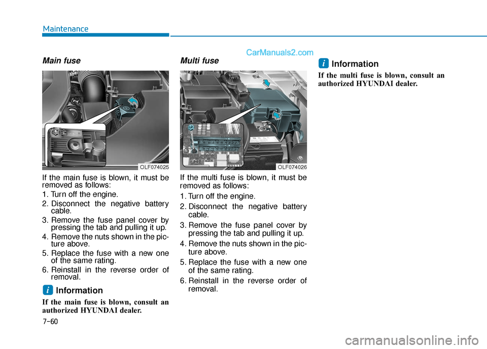
Main fuse
If the main fuse is blown, it must be
removed as follows:
1. Turn off the engine.
2. Disconnect the negative batterycable.
3. Remove the fuse panel cover by pressing the tab and pulling it up.
4. Remove the nuts shown in the pic- ture above.
5. Replace the fuse with a new one of the same rating.
6. Reinstall in the reverse order of removal.
Information
If the main fuse is blown, consult an
authorized HYUNDAI dealer.
Multi fuse
If the multi fuse is blown, it must be
removed as follows:
1. Turn off the engine.
2. Disconnect the negative battery
cable.
3. Remove the fuse panel cover by pressing the tab and pulling it up.
4. Remove the nuts shown in the pic- ture above.
5. Replace the fuse with a new one of the same rating.
6. Reinstall in the reverse order of removal.
Information
If the multi fuse is blown, consult an
authorized HYUNDAI dealer.
i
i
OLF074025OLF074026
Page 513 of 563

7-68
Maintenance
Engine compartment main fuse panel
Fuse Name Fuse rating Protected Component
FUSE
B/UP LAMP10ATransaxle Range Switch, PCM (G4KJ/G4KH-A/T), TCM (G4FJ-DCT), Audio,
Electro Chromic Mirror, Rear Combination Lamp (IN) LH/RH
1 SENSOR15AOxygen Sensor (Up/Down)
2 SENSOR15A
Purge Control Solenoid Valve, Canister Close Valve, RCV Control Solenoid Valve,
Fuel Pump Relay, E/R Junction Block (RLY. 12 - Cooling Fan 2 Relay),
[G4KJ/G4KH] Variable Intake Solenoid Valve, Oil Control Valve (Exhaust),
[G4FJ] Oil Control Valve #1/#2 (Intake/Exhaust)
1 ECU10APCM/ECM
1 TCU10APCM (G4KJ/G4KH-A/T), TCM (G4FJ-DCT)
1 ECU10APCM/ECM
IGN COIL20AIgnition Coil #1/#2/#3/#4, Condenser (G4FJ)
INJECTOR15A-
AMS10ABattery Sensor