2017 HYUNDAI IX20 ECO mode
[x] Cancel search: ECO modePage 67 of 456
Safety features of your vehicle
50
3
✽✽
NOTICE
When the passenger’s front air bag
ON/OFF switch is set to the ON position,
the passenger’s front air bag is activated
and child or infant seat should not be
installed on the front passenger seat.
When the passenger’s front air bag ON/OFF switch is set to the OFF posi-
tion, the passenger’s front air bag is
deactivated.
CAUTION
If the passenger’s front air bag
ON/OFF switch is not workingproperly, the air bag warning light
()on the instrument panel will
illuminate.
And, the passenger's front air bagOFF indicator
() will not illumi-
nate (The passenger's front air bag ON indicator comes on and
goes off after approximately 60seconds), the SRS ControlModule reactivate the passen-
ger’s front air bag and the pas-senger’s front air bag will inflate
in frontal impact crashes even if the passenger’s front air bag
ON/OFF switch is set to the OFFposition.
If this occurs, we recommend thatthe system be inspected by anauthorized HYUNDAI dealer.
(Continued)
(Continued) If the SRS air bag warning light blinks or does not illuminate
when the ignition switch is turnedto the ON position, or if it illumi-
nates while the vehicle is beingdriven, we recommend that the
system be inspected by an authorized HYUNDAI dealer.WARNING
On some models, the front air bag
ON/OFF switch could turn by using
a similar small rigid device. Always
check the status of the front air bag
ON/OFF switch and passenger's
front air bag ON/OFF indicator.
procarmanuals.com
Page 123 of 456
445
Features of your vehicle
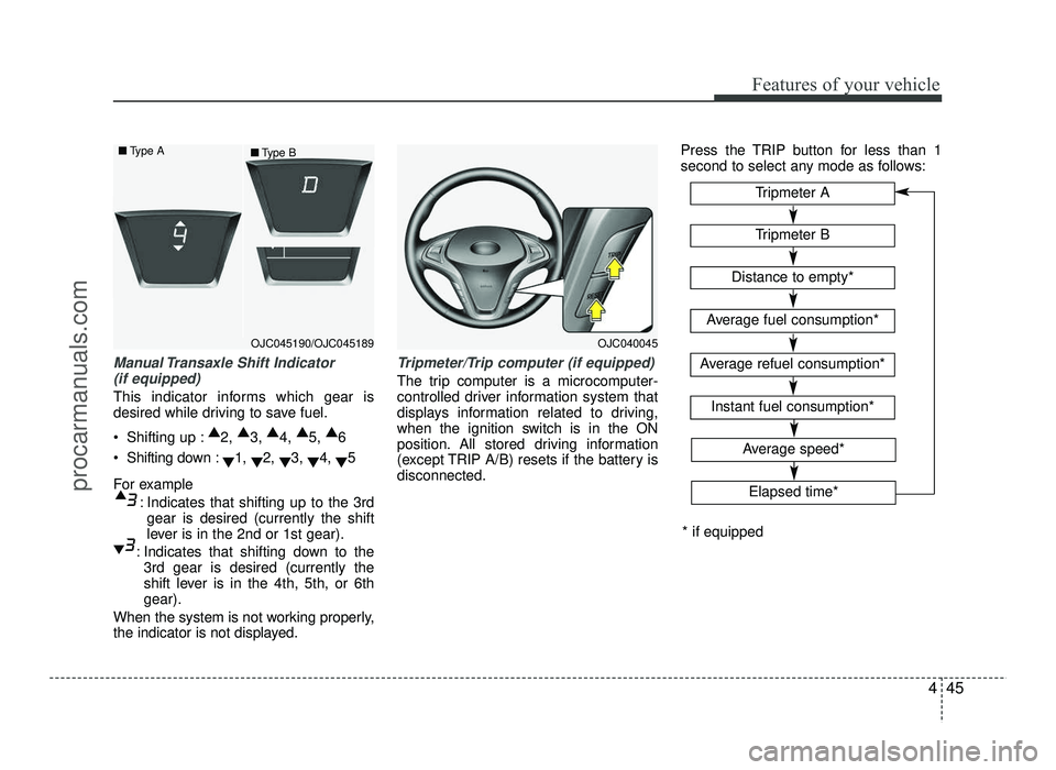
Manual Transaxle Shift Indicator (if equipped)
This indicator informs which gear is
desired while driving to save fuel.
Shifting up : ▲
2, ▲
3, ▲
4, ▲
5, ▲
6
Shifting down : ▼1,
▼2,
▼3,
▼4,
▼5
For example : Indicates that shifting up to the 3rdgear is desired (currently the shift
lever is in the 2nd or 1st gear).
: Indicates that shifting down to the 3rd gear is desired (currently the
shift lever is in the 4th, 5th, or 6thgear).
When the system is not working properly,
the indicator is not displayed.
Tripmeter/Trip computer (if equipped)
The trip computer is a microcomputer-
controlled driver information system that
displays information related to driving,
when the ignition switch is in the ON
position. All stored driving information
(except TRIP A/B) resets if the battery isdisconnected. Press the TRIP button for less than 1
second to select any mode as follows:
OJC040045
Tripmeter B
Instant fuel consumption*
Tripmeter A
Distance to empty*
Average fuel consumption*
Average refuel consumption*
* if equipped
Elapsed time*
Average speed*
OJC045190/OJC045189
■
Type A
■Type B
procarmanuals.com
Page 124 of 456
Features of your vehicle
46
4
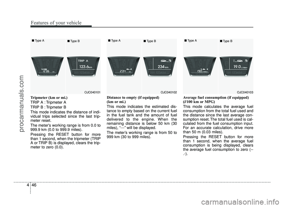
Tripmeter (km or mi.)
TRIP A : Tripmeter A
TRIP B : Tripmeter BThis mode indicates the distance of indi-
vidual trips selected since the last trip-meter reset.
The meter's working range is from 0.0 to 999.9 km (0.0 to 999.9 miles).
Pressing the RESET button for more
than 1 second, when the tripmeter (TRIP
A or TRIP B) is displayed, clears the trip-
meter to zero (0.0). Distance to empty (if equipped)
(km or mi.) This mode indicates the estimated dis- tance to empty based on the current fuelin the fuel tank and the amount of fuel
delivered to the engine. When the
remaining distance is below 50 km (30
miles), “---” will be displayed.
The meter’s working range is from 50 to 999 km (30 to 999 miles).
Average fuel consumption (if equipped)(
l/100 km or MPG)
This mode calculates the average fuelconsumption from the total fuel used and
the distance since the last average con-
sumption reset. The total fuel used is cal-culated from the fuel consumption input.
For an accurate calculation, drive morethan 50 m (0.03 miles).
Pressing the RESET button for more
than 1 second, when the average fuel
consumption is being displayed, clears
the average fuel consumption to zero (--.-).
OJC040101
■
Type A
■Type BOJC040102
■
Type A
■Type BOJC040103
■
Type A
■Type B
procarmanuals.com
Page 125 of 456
447
Features of your vehicle
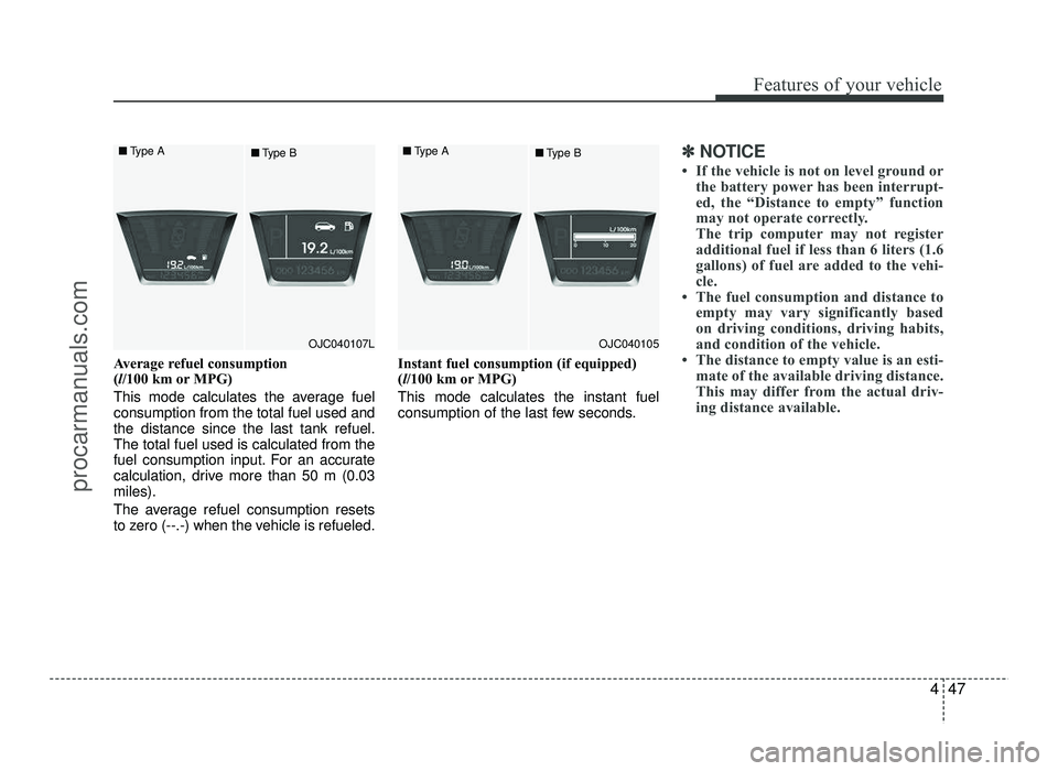
Average refuel consumption (l/100 km or MPG)
This mode calculates the average fuelconsumption from the total fuel used andthe distance since the last tank refuel.The total fuel used is calculated from the
fuel consumption input. For an accurate
calculation, drive more than 50 m (0.03miles).
The average refuel consumption resets
to zero (--.-) when the vehicle is refueled. Instant fuel consumption (if equipped)(
l/100 km or MPG)
This mode calculates the instant fuel
consumption of the last few seconds.
✽✽ NOTICE
If the vehicle is not on level ground or the battery power has been interrupt-
ed, the “Distance to empty” function
may not operate correctly.
The trip computer may not register
additional fuel if less than 6 liters (1.6
gallons) of fuel are added to the vehi-
cle.
The fuel consumption and distance to empty may vary significantly based
on driving conditions, driving habits,
and condition of the vehicle.
The distance to empty value is an esti- mate of the available driving distance.
This may differ from the actual driv-
ing distance available.
OJC040105
■
Type A
■Type BOJC040107L
■
Type A
■Type B
procarmanuals.com
Page 126 of 456
Features of your vehicle
48
4
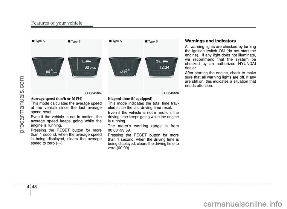
Average speed (km/h or MPH)
This mode calculates the average speed
of the vehicle since the last averagespeed reset.
Even if the vehicle is not in motion, the
average speed keeps going while the
engine is running.
Pressing the RESET button for more
than 1 second, when the average speed
is being displayed, clears the average
speed to zero (---). Elapsed time (if equipped)
This mode indicates the total time trav-
eled since the last driving time reset.
Even if the vehicle is not in motion, the
driving time keeps going while the engine
is running.
The meter’s working range is from 00:00~99:59.
Pressing the RESET button for more
than 1 second, when the driving time is
being displayed, clears the driving time to
zero (00:00). Warnings and indicators
All warning lights are checked by turning
the ignition switch ON (do not start the
engine). If any light does not illuminate,
we recommend that the system be
checked by an authorized HYUNDAI
dealer.
After starting the engine, check to make
sure that all warning lights are off. If anyare still on, this indicates a situation thatneeds attention.
OJC040104
■
Type A
■Type BOJC040106
■
Type A
■Type B
procarmanuals.com
Page 134 of 456
Features of your vehicle
56
4
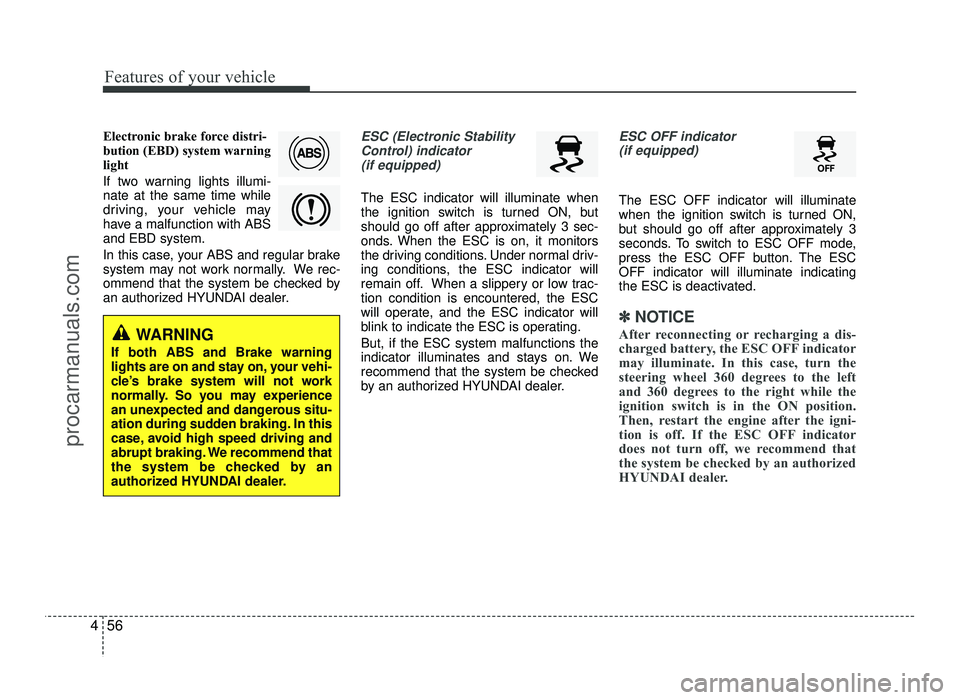
Electronic brake force distri-
bution (EBD) system warning
light
If two warning lights illumi- nate at the same time while
driving, your vehicle may
have a malfunction with ABSand EBD system.
In this case, your ABS and regular brake
system may not work normally. We rec-
ommend that the system be checked by
an authorized HYUNDAI dealer.ESC (Electronic Stability
Control) indicator
(if equipped)
The ESC indicator will illuminate when
the ignition switch is turned ON, but
should go off after approximately 3 sec-
onds. When the ESC is on, it monitors
the driving conditions. Under normal driv-
ing conditions, the ESC indicator will
remain off. When a slippery or low trac-tion condition is encountered, the ESC
will operate, and the ESC indicator will
blink to indicate the ESC is operating. But, if the ESC system malfunctions the
indicator illuminates and stays on. We
recommend that the system be checked
by an authorized HYUNDAI dealer.
ESC OFF indicator (if equipped)
The ESC OFF indicator will illuminate
when the ignition switch is turned ON,
but should go off after approximately 3
seconds. To switch to ESC OFF mode,
press the ESC OFF button. The ESCOFF indicator will illuminate indicating
the ESC is deactivated.
✽✽ NOTICE
After reconnecting or recharging a dis-
charged battery, the ESC OFF indicator
may illuminate. In this case, turn the
steering wheel 360 degrees to the left
and 360 degrees to the right while the
ignition switch is in the ON position.
Then, restart the engine after the igni-
tion is off. If the ESC OFF indicator
does not turn off, we recommend that
the system be checked by an authorized
HYUNDAI dealer.
WARNING
If both ABS and Brake warning
lights are on and stay on, your vehi-
cle’s brake system will not work
normally. So you may experience
an unexpected and dangerous situ-
ation during sudden braking. In this
case, avoid high speed driving and
abrupt braking. We recommend that
the system be checked by an
authorized HYUNDAI dealer.
procarmanuals.com
Page 136 of 456
Features of your vehicle
58
4
AUTO STOP indicator
(if equipped)
This indicator will illuminate when the engine enters the Idle Stop mode of theISG (Idle Stop and Go) system.
When the automatic starting occurs, the
"AUTO STOP" indicator on the cluster
will blink for 5 seconds.
For more details, refer to the “ISG (Idle
Stop and Go) system” in section 5.
✽✽ NOTICE
When the engine automatically starts by
the ISG system, some warning
lights(ABS, ESC, ESC OFF, EPS or
Parking brake warning light) may turn
on for a few seconds.
This happens because of low battery
voltage. It does not mean the system has
malfunctioned.
Sunroof open warning chime (if equipped)
If the driver turns off the engine and
opens the driver-side door when the sun-
roof is not fully closed, the warning chime
will sound for approximately 7 seconds.
Close the sunroof securely when leaving
your vehicle.
Glow indicator (Diesel engine)
The indicator illuminates when the igni-
tion switch is in the ON position. The
engine can be started after the preheat
indicator light goes off. The illuminating
time varies with the water temperature,
air temperature and battery condition.
✽✽ NOTICE
If the engine does not start within 10
seconds after the preheating is complet-
ed, turn the ignition key once more to
the LOCK position for 10 seconds, and
then to the ON position, in order to pre-
heat again.
CAUTION
If the preheat indicator continues to illuminate or blinks on and off after
the engine has warmed up or whiledriving, we recommend that the
system be checked by an author-ized HYUNDAI dealer.
procarmanuals.com
Page 162 of 456
Features of your vehicle
84
4
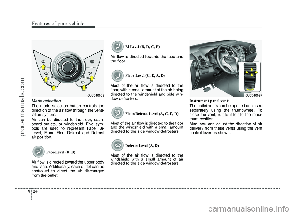
Mode selection
The mode selection button controls the
direction of the air flow through the venti-lation system.
Air can be directed to the floor, dash-
board outlets, or windshield. Five sym-
bols are used to represent Face, Bi-
Level, Floor, Floor-Defrost and Defrostair position.
Face-Level (B, D)
Air flow is directed toward the upper body
and face. Additionally, each outlet can becontrolled to direct the air dischargedfrom the outlet.
Bi-Level (B, D, C, E)
Air flow is directed towards the face and
the floor.
Floor-Level (C, E, A, D)
Most of the air flow is directed to the
floor, with a small amount of the air beingdirected to the windshield and side win-
dow defrosters.
Floor/Defrost-Level (A, C, E, D)
Most of the air flow is directed to the floor and the windshield with a small amount
directed to the side window defrosters.
Defrost-Level (A, D)
Most of the air flow is directed to thewindshield with a small amount of air
directed to the side window defrosters. Instrument panel vents
The outlet vents can be opened or closed
separately using the thumbwheel. To
close the vent, rotate it left to the maxi-
mum position.
Also, you can adjust the direction of air
delivery from these vents using the vent
control lever as shown.
OJC040059OJC040097
procarmanuals.com