2017 Hyundai Ioniq Hybrid fuses
[x] Cancel search: fusesPage 25 of 553

H10
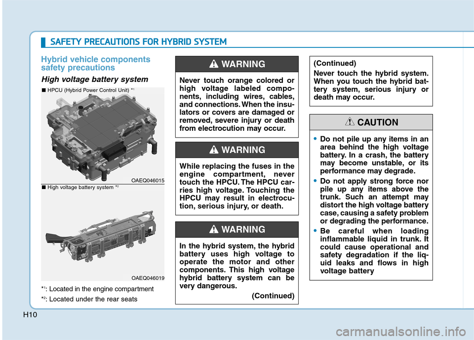
Hybrid vehicle components
safety precautions
High voltage battery system
*1
: Located in the engine compartment
* 2
: Located under the rear seats
OAEQ046015
OAEQ046019
■ HPCU (Hybrid Power Control Unit) * 1
■
High voltage battery system * 2Never touch orange colored or
high voltage labeled compo-
nents, including wires, cables,
and connections. When the insu-
lators or covers are damaged or
removed, severe injury or death
from electrocution may occur.
WARNING
While replacing the fuses in the
engine compartment, never
touch the HPCU. The HPCU car-
ries high voltage. Touching the
HPCU may result in electrocu-
tion, serious injury, or death.
WARNING
(Continued)
Never touch the hybrid system.
When you touch the hybrid bat-
tery system, serious injury or
death may occur.
In the hybrid system, the hybrid
battery uses high voltage tooperate the motor and other
components. This high voltage
hybrid battery system can be
very dangerous.
(Continued)
WARNING
Do not pile up any items in an
area behind the high voltage
battery. In a crash, the battery
may become unstable, or its
performance may degrade.
Do not apply strong force nor
pile up any items above the
trunk. Such an attempt may
distort the high voltage battery
case, causing a safety problem
or degrading the performance.
Be careful when loading
inflammable liquid in trunk. Itcould cause operational and
safety degradation if the liq-
uid leaks and flows in high
voltage battery
CAUTION
SSAA FFEE TT YY PP RR EECCAA UU TTIIOO NNSS FF OO RR HH YY BBRRIIDD SS YY SSTT EEMM
Page 27 of 553

H12
When the vehicle is paint baked,do not bake over 30 minutes in
70°C (158°F) or 20 minutes in
80°C (176°F) degree.
Do not wash the engine compart- ment, using water. Water may
cause an electric shock to and
damage the electronic.
NOTICE
Never use the package mod-
ules (high voltage battery,
inverter and converter) for any
other purpose.
Do not use an unauthorized
battery charger to charge the
high voltage battery. Doing so
may result in death or serious
injury.
Never locate the high voltage
system near or in a fire.
Never drill into or strike the
package module. Otherwise, it
may be damaged. An electric
shock may occur, resulting in
serious injury or death.
WARNING
This hybrid vehicle uses the
hybrid battery system inverter
and converter to generate high
voltage. High voltage in the
hybrid battery system is very
dangerous and may cause
severe burns and electric
shock. This may result in seri-
ous injury or death.
For your safety, never touch,
replace, disassemble or remove
the hybrid battery system
including components, cables
and connectors. Severe burns
or electric shock may result in
serious injury or death when
you fail to follow this warning.
When the hybrid battery sys-
tem operates, the hybrid bat-
tery system can be hot. Always
be careful because burns or
electric shock may be caused
by high voltage.
(Continued)
(Continued)
Do not drop water or liquid on
to HPCU, HSG, motor and
fuses. The hybrid system com-
ponents are covered. If you
drop water or liquid on to
hybrid system compone nts, it
may result in electric shock.
WARNING
SS AA FFEE TT YY PP RR EECCAA UU TTIIOO NNSS FF OO RR HH YY BBRRIIDD SS YY SSTT EEMM (( CC OO NNTT..))
Page 167 of 553

3-65
Convenient features of your vehicle
3
Low Pressure (if equipped)
This warning message is displayed if
the tire pressure is low. The corre-
sponding tire on the vehicle will beilluminated.
For more details, refer to "Tire Pressure Monitoring System
(TPMS)" in chapter 6.
Turn on "FUSE SWITCH"
This warning message is displayed if
the fuse switch located on the fuse
box under the steering wheel is OFF.
You should turn the fuse switch on.
For more details, refer to “Fuses”
in chapter 7.
Low Washer Fluid (if equipped)
This warning message is displayed
if the washer fluid level in the reser-
voir is nearly empty.
Have the washer fluid reservoir refilled.
Low Fuel
This warning message is displayed ifthe fuel tank is almost out of fuel.
When this message is displayed, the
low fuel level warning light in thecluster will come on.
It is recommended to look for the nearest fueling station and refuel as
soon as possible.
Add fuel as soon as possible.
Engine has overheated
This warning message is displayed
when the engine coolant tempera-
ture is above 120°C (248°F). This
means that the engine is overheated
and may be damaged.
If your vehicle is overheated, refer
to "Overheating" in chapter 6.
Lights Mode
■Type B
■
Type A
OAE046114L/OAE046115LOLFH044149L
Page 423 of 553

Tires and wheels ..................................................7-41Tire care ............................................................................7-41
Recommended cold tire inflation pressures ...........7-42
Check tire inflation pressure........................................7-43
Tire rotation .....................................................................7-44
Wheel alignment and tire balance ..............................7-45
Tire replacement ............................................................7-45
Wheel replacement .........................................................7-46
Tire traction ....................................................................7-46
Tire maintenance ............................................................7-47
Tire sidewall labeling ......................................................7-47
Low aspect ratio tires ....................................................7-51
Fuses ......................................................................7-52 Instrument panel fuse replacement ...........................7-53
Engine compartment panel fuse replacement.........7-54
Fuse/relay panel description .......................................7-56 Light bulbs.............................................................7-66
Headlamp, position lamp, turn signal lamp
bulb replacement .............................................................7-67Headlamp aiming .............................................................7-71
Daytime running lamp ....................................................7-75
Side repeater lamp replacement .................................7-75
Rear combination lamp bulb replacement ................7-76
Rear fog lamp ..................................................................7-81
High mounted stop lamp ...............................................7-81
License plate light bulb replacement .........................7-81
Interior light bulb replacement ....................................7-81
Appearance care ..................................................7-83 Exterior care ....................................................................7-83
Interior care......................................................................7-88
Emission control system .....................................7-90 Crankcase emission control system ...........................7-90
Evaporative emission control system.........................7-90
Exhaust emission control system ...............................7-91
Page 473 of 553

7-52
MaintenanceF
F UU SSEE SS
A vehicle’s electrical system is pro-
tected from electrical overload dam-
age by fuses.
This vehicle has 2 (or 3) fuse panels,
one located in the driver’s side panel
bolster, the other in the engine com-
partment.
If any of your vehicle’s lights, acces-
sories, or controls do not work, check
the appropriate circuit fuse. If a fuse
has blown, the element inside the
fuse will be melted or broken.
If the electrical system does not
work, first check the driver’s side
fuse panel. Before replacing a blown
fuse, turn the engine and all switches
off, and then disconnect the negative
battery cable. Always replace a
blown fuse with one of the same rat-ing.
If the replacement fuse blows, this indi-
cates an electrical problem. Avoid
using the system involved and immedi-
ately consult an authorized HYUNDAI
dealer. Information
Three kinds of fuses are used: blade
type for lower amperage rating, car-
tridge type, and multi fuse for higher
amperage ratings.i
Normal
■
Blade type
■ Cartridge type Blown
Normal Blown
Normal Blown
OLF074075 Do not use a screwdriver or any
other metal object to remove
fuses because it may cause a
short circuit and damage thesystem.
CAUTION
NEVER replace a fuse with any-
thing but another fuse of thesame rating.
A higher capacity fuse could
cause damage and possibly
cause a fire.
Do not install a wire or alu-
minum foil instead of the
proper fuse - even as a tem-
porary repair. It may cause
extensive wiring damage and
possibly a fire.
WARNING
Normal
Blown
■ Multi fuse
Page 474 of 553

7-53
Maintenance
Instrument panel fuse replace- ment
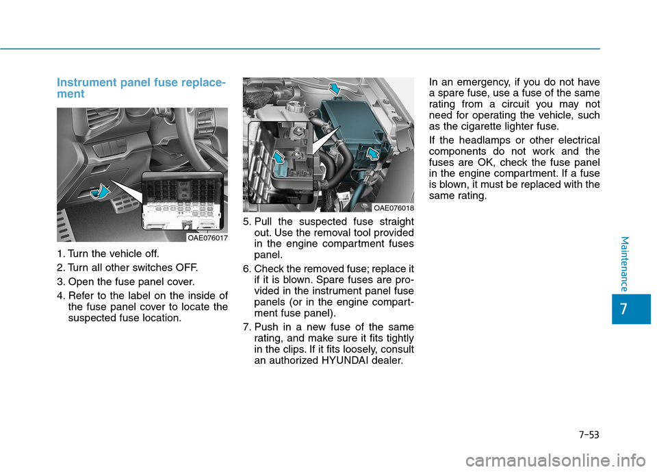
1. Turn the vehicle off.
2. Turn all other switches OFF.
3. Open the fuse panel cover.
4. Refer to the label on the inside ofthe fuse panel cover to locate the suspected fuse location. 5. Pull the suspected fuse straight
out. Use the removal tool provided
in the engine compartment fusespanel.
6. Check the removed fuse; replace it if it is blown. Spare fuses are pro-
vided in the instrument panel fuse
panels (or in the engine compart-ment fuse panel).
7. Push in a new fuse of the same rating, and make sure it fits tightly
in the clips. If it fits loosely, consult
an authorized HYUNDAI dealer. In an emergency, if you do not have
a spare fuse, use a fuse of the same
rating from a circuit you may not
need for operating the vehicle, such
as the cigarette lighter fuse.
If the headlamps or other electrical
components do not work and the
fuses are OK, check the fuse panel
in the engine compartment. If a fuse
is blown, it must be replaced with the
same rating.
OAE076017
OAE076018
7
Page 476 of 553

7-55
7
Maintenance
4. Check the removed fuse; replace itif it is blown. To remove or insert
the fuse, use the fuse puller in the
engine compartment fuse panel.
5. Push in a new fuse of the same rating, and make sure it fits tightly
in the clips. If it fits loosely, consult
an authorized HYUNDAI dealer.
After checking the fuse panel in
the engine compartment, securely
install the fuse panel cover. You
may hear a clicking sound if the
cover is securely latched. If it is
not securely latched, electrical
failure may occur from water con-tact.Main fuse
The electronic system may not func-
tion correctly even when the fuses
located in the engine compartment
and instrument panel are not discon-
nected. In such case, the cause of
the problem may be disconnection ofthe main fuse (BFT type), which is
located inside the positive battery
terminal (+) cap. Since the main fuse
is designed more intricately than
other parts, we recommend you visit
the nearest HYUNDAI dealer. Information
After inspection always securely
install the battery cap. If it is not
securely latched, electrical failure may
occur from water contact.
Multi fuse
If the multi fuse is blown, it must be
removed as follows:
1. Turn the vehicle off.
2. Disconnect the negative battery cable.
3. Remove the fuse panel cover by pressing the tab and pulling it up.
4. Remove the nuts shown in the pic- ture above.
5. Replace the fuse with a new one of the same rating.
6. Reinstall in the reverse order of removal.
Information
If the multi fuse is blown, consult an
authorized HYUNDAI dealer.
i
i
NOTICE
OAE076021OAE076022
Page 546 of 553

I-5
Easy access function .....................................................3-19
ECO mode ....................................................................5-20
Electric chromic mirror (ECM) ....................................3-23
Electric power steering (EPS) ......................................3-20
Electronic stability control (ESC) ................................5-31
Emergency commodity .................................................6-36
Emergency stop signal (ESS) .......................................5-36
Emergency towing ........................................................6-34
Emission control system ...............................................7-90
Crankcase emission control system ...........................7-90
Evaporative emission control System .......................7-90
Exhaust emission control system...............................7-91
Engine compartment ...............................................1-8, 7-3
Engine compartment panel fuse replacement...............7-54
Engine coolant ..............................................................7-24
Engine coolant temperature guage ...............................3-46
Engine number................................................................8-9
Engine oil......................................................................7-22
Engine specification .......................................................8-2
Engine Start/Stop button.................................................5-9
Evaporative emission control System ..........................7-90
Exhaust emission control system .................................7-91
Explanation of scheduled maintenance items ..............7-20
Exterior care .................................................................7-83
Exterior overview Front view ....................................................................1-2
Rear view .....................................................................1-3 Flat tire
Changing tires ............................................................6-17
EC Declaration of conformity for Jack .....................6-23
Jack and tools.............................................................6-16
Jack label ...................................................................6-22
Tire Mobility Kit (TMK) ...........................................6-24
Use of compact spare tires.........................................6-20
Floor mat anchor(s) ....................................................3-138
Fluid Brake fluid .................................................................7-28
Washer fluid ...............................................................7-29
Front seat adjustment......................................................2-7 Forward and rearward adjustment .............................2-18
Manual adjustment.......................................................2-8
Power adjustment.......................................................2-10
Removal/Reinstall......................................................2-18
Seatback pocket .........................................................2-13
Fuel filler door ..............................................................3-39
Fuel gauge.....................................................................3-45
Fuel requirements ...........................................................F-6
Fuse switch ...................................................................7-54
Fuses .............................................................................7-52 Engine compartment panel fuse replacement ............7-54
Fuse switch ................................................................7-54
Fuse/relay panel description ......................................7-56
Instrument panel fuse replacement ............................7-53
Main fuse ...................................................................7-55
Multi fuse ...................................................................7-55
I
Index
EF