2017 Hyundai Ioniq Hybrid fuel
[x] Cancel search: fuelPage 462 of 553
7-41
7
Maintenance
TTIIRR EESS AA NN DD WW HHEEEELLSS
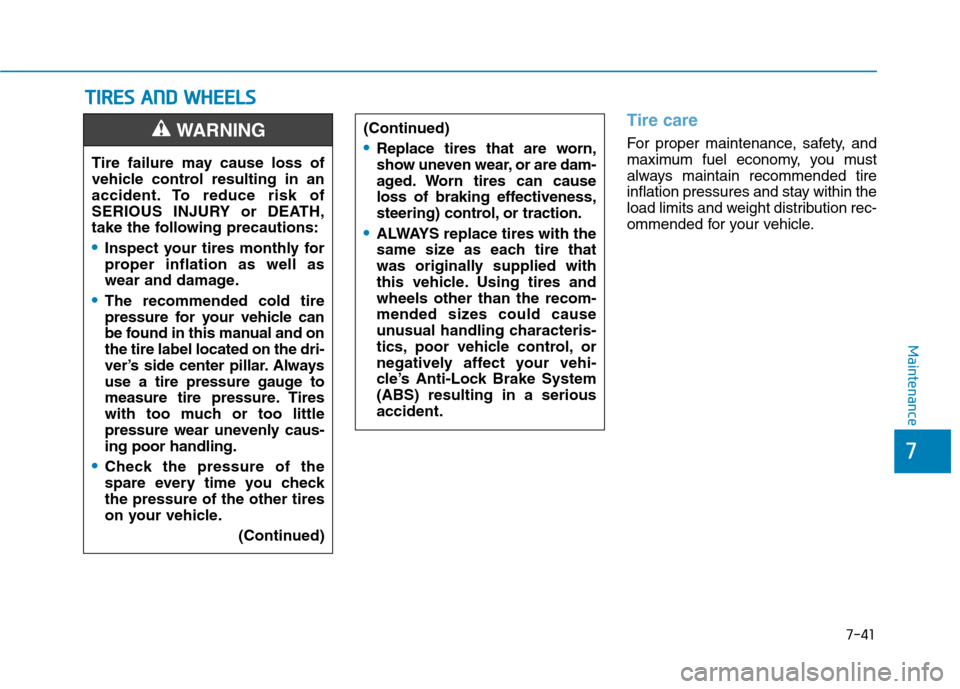
Tire care
For proper maintenance, safety, and
maximum fuel economy, you must
always maintain recommended tire
inflation pressures and stay within the
load limits and weight distribution rec-
ommended for your vehicle.
(Continued)Replace tires that are worn,
show uneven wear, or are dam-
aged. Worn tires can cause
loss of braking effectiveness,
steering) control, or traction.
ALWAYS replace tires with the
same size as each tire that
was originally supplied with
this vehicle. Using tires andwheels other than the recom-
mended sizes could cause
unusual handling characteris-
tics, poor vehicle control, or
negatively affect your vehi-
cle’s Anti-Lock Brake System(ABS) resulting in a seriousaccident.
Tire failure may cause loss of
vehicle control resulting in an
accident. To reduce risk of
SERIOUS INJURY or DEATH,
take the following precautions:
Inspect your tires monthly for
proper inflation as well as
wear and damage.
The recommended cold tire
pressure for your vehicle can
be found in this manual and onthe tire label located on the dri-
ver’s side center pillar. Always
use a tire pressure gauge to
measure tire pressure. Tires
with too much or too little
pressure wear unevenly caus-ing poor handling.
Check the pressure of the
spare every time you checkthe pressure of the other tires
on your vehicle.
(Continued)
WARNING
Page 464 of 553
7-43
7
Maintenance
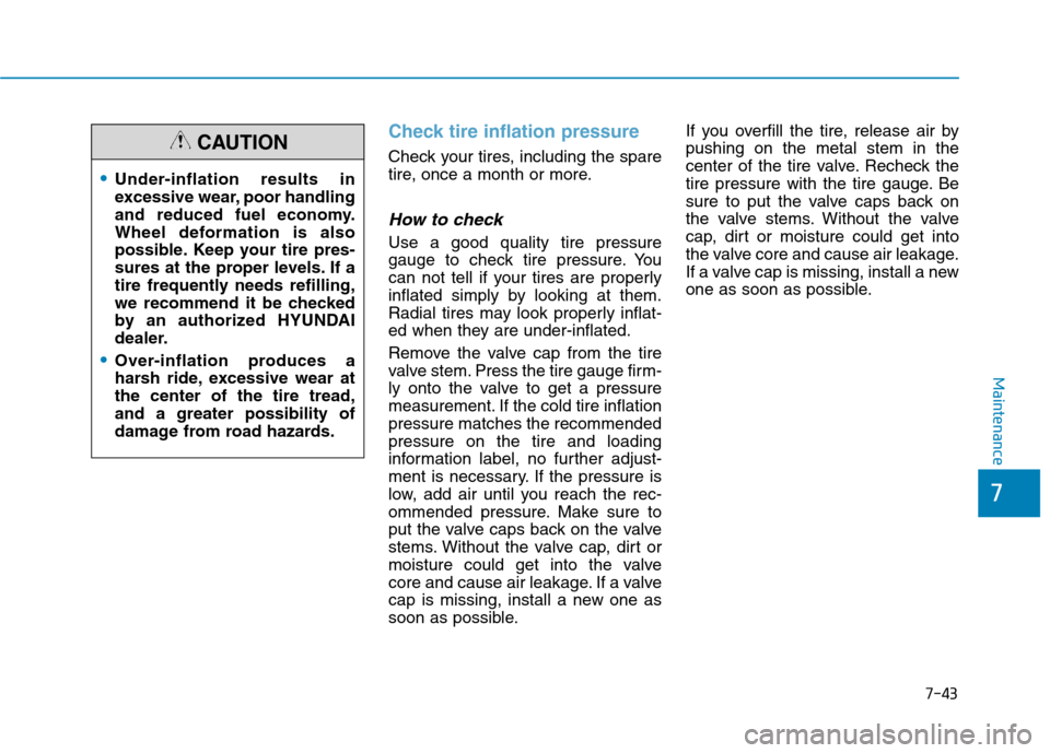
Check tire inflation pressure
Check your tires, including the spare
tire, once a month or more.
How to check
Use a good quality tire pressure
gauge to check tire pressure. You
can not tell if your tires are properly
inflated simply by looking at them.
Radial tires may look properly inflat-
ed when they are under-inflated.
Remove the valve cap from the tire
valve stem. Press the tire gauge firm-
ly onto the valve to get a pressure
measurement. If the cold tire inflationpressure matches the recommendedpressure on the tire and loading
information label, no further adjust-
ment is necessary. If the pressure is
low, add air until you reach the rec-
ommended pressure. Make sure to
put the valve caps back on the valve
stems. Without the valve cap, dirt or
moisture could get into the valve
core and cause air leakage. If a valve
cap is missing, install a new one as
soon as possible.If you overfill the tire, release air bypushing on the metal stem in the
center of the tire valve. Recheck the
tire pressure with the tire gauge. Be
sure to put the valve caps back on
the valve stems. Without the valve
cap, dirt or moisture could get into
the valve core and cause air leakage.
If a valve cap is missing, install a new
one as soon as possible.
Under-inflation results in
excessive wear, poor handling
and reduced fuel economy.
Wheel deformation is also
possible. Keep your tire pres-
sures at the proper levels. If a
tire frequently needs refilling,
we recommend it be checked
by an authorized HYUNDAI
dealer.
Over-inflation produces a
harsh ride, excessive wear atthe center of the tire tread,and a greater possibility of
damage from road hazards.
CAUTION
Page 479 of 553

7-58
Maintenance
Fuse NameSymbolFuse RatingCircuit Protected
Module 2MODULE210AE/R Junction Block, Wireless Charger Unit, BCM, USB Charging Connector, Smart Key
Control Module, Audio, A/V & Navigation Head Unit, Power Outside Mirror Switch, AMP
Button Start 337.5AImmobilizer Module, Smart Key Control Module
Memory 1MEMORY
110AWireless Charger Unit, Instrument Cluster, Driver Ims Module, Rain Sensor, BCM,
A/C Control Module, Auto Light & Photo Sensor, Driver Door Module,
Passenger Door Module, ICM Relay Box (Outside Mirror Folding/Unfolding Relay)
Multi MediaMULTI
MEDIA10AAudio, A/V & Navigation Head Unit
Electric Water
PumpEEWP10AElectric Water Pump (HEV)
Electric
Power Steering 117.5AEPS Unit
Tailgate10ATail Gate Relay, Fuel Filler Switch, Fuel Filler Actuator
Button Start 1115ASmart Key Control Module
Module 7MODULE 77.5AFront Seat Warmer Control Module, Front Air Ventilation Seat Control Module,
Rear Seat Warmer Module
Heated Steering15ABCM
Sunroof20ASunroof Motor
Power Window
Right-handRH25APower Window (RH) Relay, Power Window Main Switch, Passenger Power Window Switch
(LHD), Rear Power Window Switch (RH), Driver Safety Power Window Module (LHD),
Passenger Power Window Switch (RHD)
Instrument panel fuse panel
Page 486 of 553

7-65
7
Maintenance
TypeSymbolFuse RatingCircuit Protected
Fuse
S310AFuel Pump Relay, Camshaft Position Sensor #1 (Intake), Camshaft Position Sensor #2
(Exhaust), Oil Control Valve #1 (Intake), Oil Control Valve #2 (Exhaust)
BATTERYC/FAN15AEngine Room Junction Block
FUEL
PUMP20AFuel Pump Relay
20AHorn Relay
Engine compartment fuse panel
Page 506 of 553
7-85
7
Maintenance
Finish damage repair
Deep scratches or stone chips in the
painted surface must be repaired
promptly. Exposed metal will quickly
rust and may develop into a major
repair expense.
If your vehicle is damaged and
requires any metal repair or
replacement, be sure the body
shop applies anti-corrosion mate-
rials to the parts repaired orreplaced.
Bright-metal maintenance
To remove road tar and insects,use a tar remover, not a scraper or
other sharp object.
To protect the surfaces of bright- metal parts from corrosion, apply a
coating of wax or chrome preser-
vative and rub to a high luster.
During winter weather or in coastal areas, cover the bright metal parts
with a heavier coating of wax or
preservative. If necessary, coat the
parts with non-corrosive petroleum
jelly or other protective compound.
Underbody maintenance
Corrosive materials used for ice and
snow removal and dust control may
collect on the underbody. If these
materials are not removed, acceler-
ated rusting can occur on underbody
parts such as the fuel lines, frame,
floor pan and exhaust system, even
though they have been treated with
rust protection.
Thoroughly flush the vehicle under-
body and wheel openings with luke-
warm or cold water once a month,
after off-road driving and at the end
of each winter. Pay special attentionto these areas because it is difficult
to see all the mud and dirt. It will do
more harm than good to wet down
the road grime without removing it.
The lower edges of doors, rocker
panels, and frame members have
drain holes that should not be
allowed to clog with dirt; trapped
water in these areas can cause rust-ing.
NOTICE
Page 511 of 553
7-90
MaintenanceE
E MM IISS SSIIOO NN CC OO NNTTRR OO LL SS YY SSTT EEMM
The emission control system of your
vehicle is covered by a written limited
warranty. Please see the warranty
information contained in the Owner’s
Handbook & Warranty Information
booklet in your vehicle.
Your vehicle is equipped with an emission control system to meet all
applicable emission regulations.There are three emission control
systems, as follows.
(1) Crankcase emission control sys-
tem
(2) Evaporative emission control sys- tem
(3) Exhaust emission control systemIn order to assure the proper function
of the emission control systems, it is
recommended that you have your
vehicle inspected and maintained by
an authorized HYUNDAI dealer inaccordance with the maintenance
schedule in this manual.1. Crankcase emission control system
The positive crankcase ventilation
system is employed to prevent air
pollution caused by blow-by gases
being emitted from the crankcase.This system supplies fresh filtered air
to the crankcase through the air
intake hose. Inside the crankcase,
the fresh air mixes with blow-by
gases, which then pass through the
PCV valve into the induction system.
2. Evaporative emission controlsystem
The Evaporative Emission Control
System is designed to prevent fuel
vapors from escaping into the atmos-
phere.
For the Inspection and
Maintenance Test (With Electronic
Stability Control (ESC) system)
To prevent the vehicle from
misfiring during dynamome-
ter testing, turn the Electronic
Stability Control (ESC) sys-
tem off by pressing the ESC
switch (ESC OFF light illumi-nated).
After dynamometer testing is
completed, turn the ESC sys-
tem back on by pressing the
ESC switch again.
CAUTION
Page 512 of 553
7-91
7
Maintenance
Canister
Fuel vapors generated inside the fuel tank are absorbed and stored in the
onboard canister. When the engine is
running, the fuel vapors absorbed in
the canister are drawn into the surgetank through the purge control sole-
noid valve.
Purge Control Solenoid Valve(PCSV)
The purge control solenoid valve is
controlled by the Engine Control
Module (ECM); when the engine
coolant temperature is low during
idling, the PCSV closes so that evap-
orated fuel is not taken into the
engine. After the engine warms-up
during ordinary driving, the PCSV
opens to introduce evaporated fuel to
the engine.
3. Exhaust emission control system
The Exhaust Emission Control
System is a highly effective system
which controls exhaust emissions
while maintaining good vehicle per-
formance.
When the engine starts or fails to
start, excessive attempts to restart
the engine may cause damage to theemission system.
Engine exhaust (carbon monox-
ide) precautions
Carbon monoxide can be present with other exhaust fumes. If you
smell exhaust fumes of any kind in
your vehicle, drive with all the win-
dows fully open. Have your vehicle
checked and repaired immediately.
Engine exhaust gases contain
carbon monoxide (CO). Though
colorless and odorless, it is
dangerous and could be lethal if
inhaled. Follow the instructions
on this page to avoid CO poi-soning.
WARNING
Page 513 of 553
7-92
Maintenance
Do not operate the engine in con-fined or closed areas (such as
garages) any more than what is
necessary to move the vehicle in orout of the area.
When the vehicle is stopped in an open area for more than a short
time with the engine running,
adjust the ventilation system (as
needed) to draw outside air into the
vehicle.
Never sit in a parked or stopped vehicle for any extended time with
the engine running.
When the engine stalls or fails to start, excessive attempts to restart
the engine may cause damage tothe emission control system.Operating precautions for cat-
alytic converters (if equipped)Your vehicle is equipped with a cat-
alytic converter emission control
device.
To prevent damage to the catalytic
converter and to your vehicle, take
the following precautions:
The exhaust system and cat-
alytic converter are very hot
during and immediately after
the engine has been running. To
avoid SERIOUS INJURY or
DEATH:
Do not park, idle, or drive the
vehicle over or near flamma-
ble objects, such as grass,
vegetation, paper, leaves, etc.
A hot exhaust system can
ignite flammable items under
your vehicle.
Keep away from the exhaust
system and catalytic convert-
er or you may get burned.
Also, Do not remove the heat
sink around the exhaust sys-
tem, do not seal the bottom of
the vehicle, and do not coat
the vehicle for corrosion con-
trol. It may present a fire risk
under certain conditions.
WARNING
Use only UNLEADED FUEL
for gasoline engines.
Do not operate the vehicle when there are signs of
engine malfunction, such as
misfire or a noticeable loss of
performance.
Do not misuse or abuse the
engine. Examples of misuse
are coasting with the hybridsystem off and descending
steep grades in gear with the
hybrid system off.
Do not operate the engine at
high idle speed for extended
periods (5 minutes or more).
(Continued)
CAUTION