2017 FORD TAURUS ignition
[x] Cancel search: ignitionPage 218 of 504
This program is separate from the NewVehicle Limited Warranty, but the coverageis concurrent with the powertrain coverageperiod of your vehicle.
Canadian customers who require roadsideassistance, call 1-800-665-2006.
Vehicles Sold in Canada: UsingRoadside Assistance
Complete the roadside assistanceidentification card and place it in yourwallet for quick reference.
In Canada, this card is found in theWarranty Guide in the glove compartmentof your vehicle.
Vehicles Sold in Canada: RoadsideAssistance Program Coverage
The service is available 24 hours a day,seven days a week.
Canadian roadside coverage and benefitsmay differ from the U.S. coverage.
For complete program coverage detailsyou may contact your dealer, you can callus in Canada at 1-800-665-2006, or visitour website at www.ford.ca.
HAZARD WARNING FLASHERS
Note:If used when the vehicle is notrunning, the battery will lose charge. Theremay be insufficient power to restart yourvehicle.
The hazard warning button islocated on the instrument panel.Use it when your vehicle iscreating a safety hazard for othermotorists.
•Press the button to turn on the hazardwarning function, and the front andrear direction indicators will flash.
•Press the button again to turn themoff.
FUEL SHUTOFF
WARNING
Failure to inspect and, if necessary,repair fuel leaks after a collision mayincrease the risk of fire and seriousinjury. Ford Motor Company recommendsthat the fuel system be inspected by anauthorized dealer after any collision.
In the event of a moderate to severecollision, this vehicle includes a fuel pumpshutoff feature that stops the flow of fuelto the engine. Not every impact will causea shutoff.
Should your vehicle shut off after acollision, you may restart your vehicle. Forvehicles equipped with a key system:
1. Switch off the ignition.
2. Switch on the ignition.
3. Repeat Steps 1 and 2 to re-enable thefuel pump.
For vehicles equipped with a push buttonstart system:
1. Press the START/STOP button toswitch off the ignition.
2. Press the brake pedal and press theSTART/STOP button to switch on theignition.
3.Remove your foot from the brake pedaland press the START/STOP buttonto switch off the ignition.
4. You can either attempt to start theengine by pressing the brake pedal andthe START/STOP button, or switchon the ignition only by pressing theSTART/STOP button withoutpressing the brake pedal. Both waysre-enable the fuel system.
215
Taurus (CPH) Canada/United States of America, enUSA, First Printing
Roadside Emergencies
Page 232 of 504

Protected componentsFuse amp ratingFuse or relay number
Wiper relay.Relay55
Not used.-56
Left-hand high intensity discharge head-lamp.20A157
Alternator A-line.10A158
Brake on/off switch.10A159
Not used.-60
Not used.-61
A/C clutch relay.10A 162
Not used.-63
Massage control seats.15A164
Fuel pump relay.30A165Fuel injectors.
Powertrain control module relay.Relay66
Oxygen sensor heater.20A167Mass airflow sensor.Variable camshaft timing solenoid valve.Canister vent solenoid.Canister purge solenoid.
Ignition coils.20A168
Vehicle power 1 (powertrain controlmodule).20A169
A/C clutch.15A170Fan control relay coils 1-3.Variable air conditioning compressor.Auxiliary transmission warmup.Turbo charge waste-gate control.Electronic compressor bypass valve.All-wheel drive module.Positive crankcase ventilation heater.
Not used.-71
229
Taurus (CPH) Canada/United States of America, enUSA, First Printing
Fuses
Page 236 of 504

Protected componentsFuse amp ratingFuse or relay number
Audio amplifiers.20A19
All lock motor relay and coil.20A20Driver lock motor relay and coil.
Extended power module.10A21
Horn relay.20A22
Steering wheel control module logic15A23Instrument cluster.
Steering wheel control module.15A24Datalink.
Decklid release.15A25
Ignition switch.5A26Push button ignition switch.
Intelligent access module power.20A27
Not used (spare).15A28
Radio.20A29Global positioning system module.
Front park lamps.15A30
Not used (spare).5A31
Smart window motors.15A32Master window and mirror switch.Rear window power sunshade module.Lock switch illumination.
Not used (spare).10A33
Reverse park aid module.10A34Automatic high beam and lane departuremodule.Rear heated seat module.Blind spot monitor module.Rear video camera.
Motorized humidity sensor.5A35Heads-up display.Traction control switch.
Heated steering wheel.10A36
233
Taurus (CPH) Canada/United States of America, enUSA, First Printing
Fuses
Page 257 of 504
After battery replacement, or in somecases after charging the battery with anexternal charger, the battery managementsystem requires eight hours of vehicle sleeptime to relearn the battery state of charge.During this time your vehicle must remainfully locked with the ignition switched off.
Note:Prior to relearning the battery stateof charge, the battery management systemmay temporarily disable some electricalsystems.
Electrical Accessory Installation
To make sure the battery managementsystem works correctly, do not connect anelectrical device ground connectiondirectly to the battery negative post. Thiscan cause inaccurate measurements ofthe battery condition and potentialincorrect system operation.
Note:If you add electrical accessories orcomponents to the vehicle, it may adverselyaffect battery performance and durability.This may also affect the performance ofother electrical systems in the vehicle.
CHECKING THE WIPER
BLADES
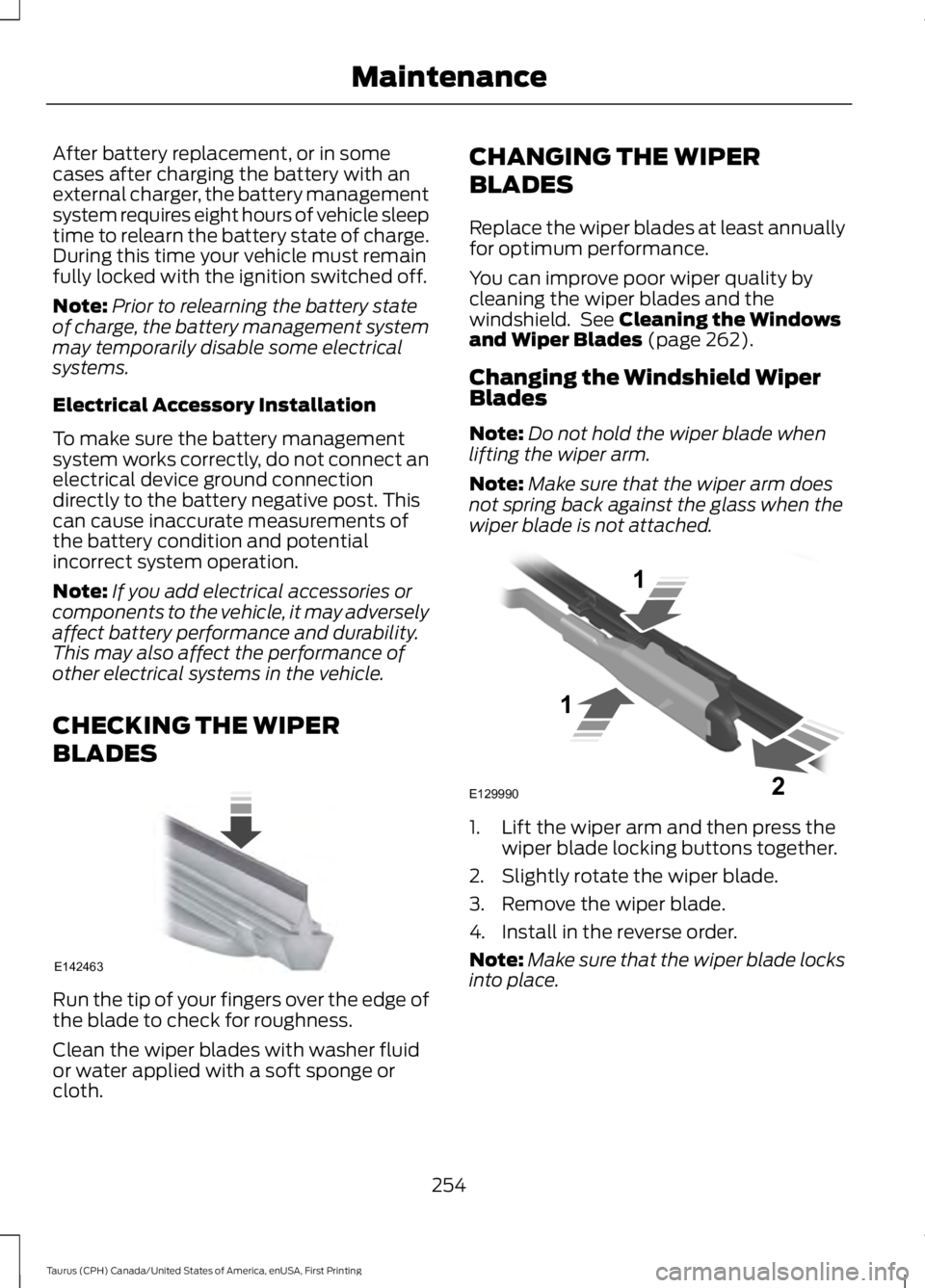
Run the tip of your fingers over the edge ofthe blade to check for roughness.
Clean the wiper blades with washer fluidor water applied with a soft sponge orcloth.
CHANGING THE WIPER
BLADES
Replace the wiper blades at least annuallyfor optimum performance.
You can improve poor wiper quality bycleaning the wiper blades and thewindshield. See Cleaning the Windowsand Wiper Blades (page 262).
Changing the Windshield WiperBlades
Note:Do not hold the wiper blade whenlifting the wiper arm.
Note:Make sure that the wiper arm doesnot spring back against the glass when thewiper blade is not attached.
1. Lift the wiper arm and then press thewiper blade locking buttons together.
2. Slightly rotate the wiper blade.
3. Remove the wiper blade.
4. Install in the reverse order.
Note:Make sure that the wiper blade locksinto place.
254
Taurus (CPH) Canada/United States of America, enUSA, First Printing
MaintenanceE142463 E129990
1
1 2
Page 259 of 504
5. Locate the vertical adjuster on eachheadlamp. Use a Phillips #2screwdriver to turn the adjuster eitherclockwise or counterclockwise toadjust the vertical aim of theheadlamp. The horizontal edge of thebrighter light should touch thehorizontal reference line.
6.Repeat Steps 3 through 7 to adjust theother headlamp.
7.Close the hood and turn off the lamps.
Horizontal Aim Adjustment
Horizontal aim is not required for thisvehicle and is not adjustable.
CHANGING A BULB
WARNINGS
Bulbs can become hot. Let the bulbcool down before removing it. Failureto do so could result in personalinjury.
Switch the lamps and the ignition off.Failure to follow this warning couldresult in serious personal injury.
Use the correct specification bulb. SeeBulb Specification Chart (page 257).
Install in the reverse order unless otherwisestated.
High-Intensity DischargeHeadlamps
These lamps operate at a high voltage. Seean authorized dealer if they fail.
Front Fog Lamp (If Equipped)
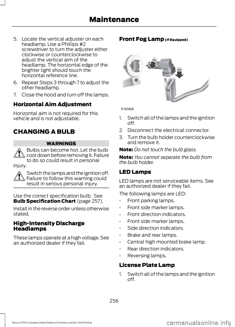
1.Switch all of the lamps and the ignitionoff.
2. Disconnect the electrical connector.
3.Turn the bulb holder counterclockwiseand remove it.
Note:Do not touch the bulb glass.
Note:You cannot separate the bulb fromthe bulb holder.
LED Lamps
LED lamps are not serviceable items. Seean authorized dealer if they fail.
The following lamps are LED:
•Front parking lamps.
•Front side marker lamps.
•Front direction indicators.
•Front side marker lamps.
•Side direction indicators.
•Brake and rear lamps.
•Central high mounted brake lamp.
•Rear direction indicators.
•Reversing lamps.
License Plate Lamp
1.Switch all of the lamps and the ignitionoff.
256
Taurus (CPH) Canada/United States of America, enUSA, First Printing
MaintenanceE163826
Page 262 of 504
CHANGING THE ENGINE AIR
FILTER
WARNING
Do not start the engine with the aircleaner removed. This can causedamage not covered by the vehicleWarranty and can result in serious injury.
When changing the air filter element, useonly the air filter element listed. SeeCapacities and Specifications (page297).
For vehicles with EcoBoost engines, whenservicing the air cleaner, it is important thatno foreign material enters the air inductionsystem. The engine and turbocharger aresusceptible to damage from even smallparticles.
Change the air filter element at the correctinterval. See Scheduled Maintenance(page 447).
Note: Failure to use the correct air filterelement may result in severe enginedamage. Resulting component damagemay not be covered by the vehicle Warranty.
To replace the air filter element do thefollowing:
1. Switch the ignition off.
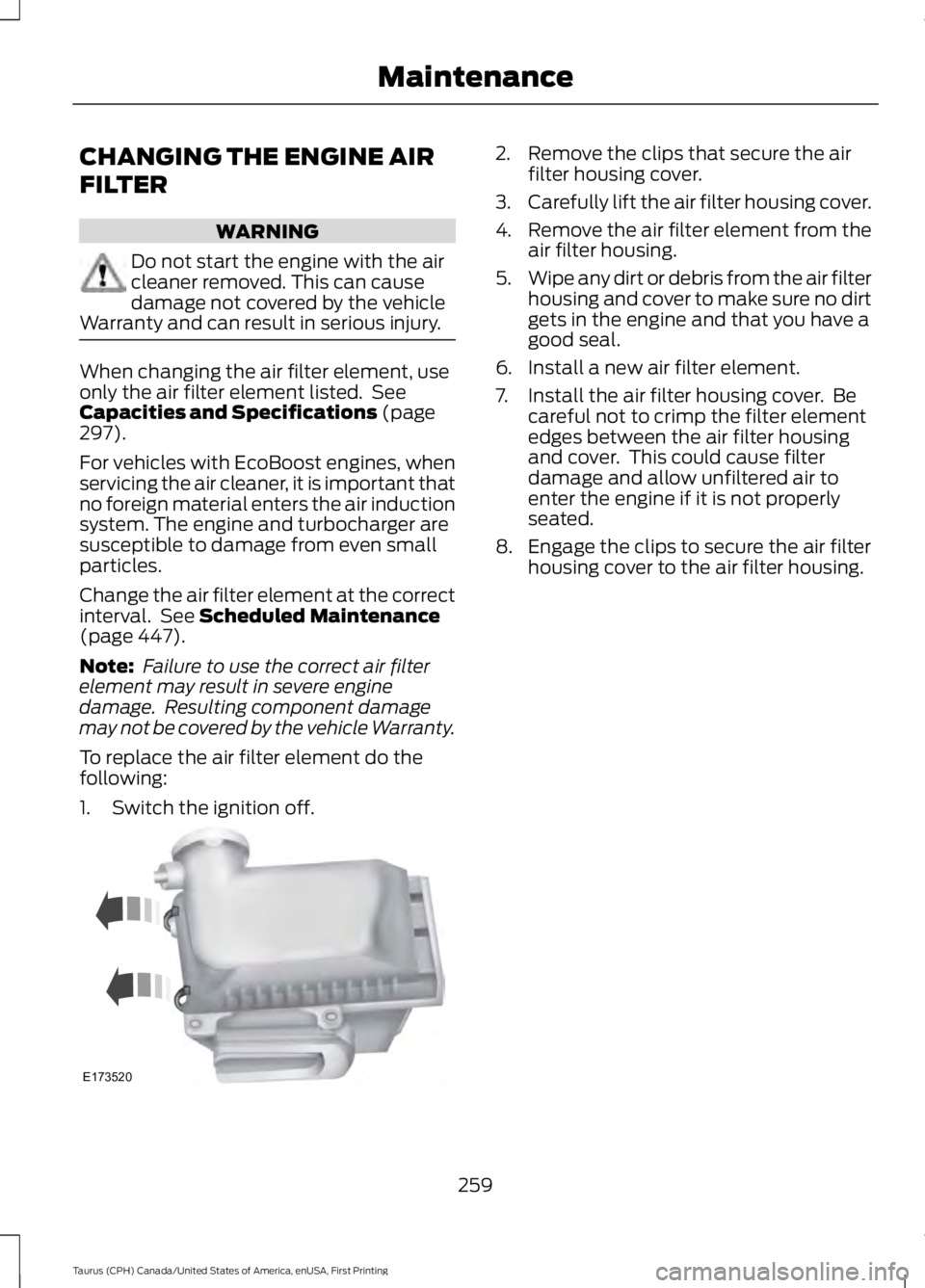
2. Remove the clips that secure the airfilter housing cover.
3.Carefully lift the air filter housing cover.
4.Remove the air filter element from theair filter housing.
5.Wipe any dirt or debris from the air filterhousing and cover to make sure no dirtgets in the engine and that you have agood seal.
6. Install a new air filter element.
7. Install the air filter housing cover. Becareful not to crimp the filter elementedges between the air filter housingand cover. This could cause filterdamage and allow unfiltered air toenter the engine if it is not properlyseated.
8. Engage the clips to secure the air filterhousing cover to the air filter housing.
259
Taurus (CPH) Canada/United States of America, enUSA, First Printing
MaintenanceE173520
Page 265 of 504
•Use a quality wax that does not containabrasives.
•Follow the manufacturer’s instructionsto apply and remove the wax.
•Apply a small amount of wax in aback-and-forth motion, not in circles.
•Do not allow wax to come in contactwith any non-body (low-gloss black)colored trim. The wax will discolor orstain the parts over time.
•Roof racks.
•Bumpers.
•Grained door handles.
•Side moldings.
•Mirror housings.
•Windshield cowl area.
•Do not apply wax to glass areas.
•After waxing, your car's paint shouldfeel smooth, and be free of streaks andsmudges.
CLEANING THE ENGINE
Engines are more efficient when they areclean because grease and dirt buildup keepthe engine warmer than normal.
When washing:
•Take care when using a power washerto clean the engine. The high-pressurefluid could penetrate the sealed partsand cause damage.
•Do not spray a hot engine with coldwater to avoid cracking the engineblock or other engine components.
•Spray Motorcraft Engine Shampoo andDegreaser on all parts that requirecleaning and pressure rinse clean. InCanada, use Motorcraft EngineShampoo.
•Never wash or rinse the engine while itis hot or running; water in the runningengine may cause internal damage.
•Never wash or rinse any ignition coil,spark plug wire or spark plug well, orthe area in and around these locations.
•Cover the battery, power distributionbox, and air filter assembly to preventwater damage when cleaning theengine.
CLEANING THE WINDOWS AND
WIPER BLADES
Car wash chemicals and environmentalfallout can result in windshield and wiperblade contamination. Dirty windshield andwipers will result in poor windshield wiperoperation. Keep the windshield and wiperblades clean to maintain windshield wiperperformance.
To clean the windshield and wiper blades:
•Clean the windshield with anon-abrasive glass cleaner. Whencleaning the interior of the windshield,avoid getting any glass cleaner on theinstrument panel or door panels. Wipeany glass cleaner off these surfacesimmediately.
•For windshields contaminated withtree sap, chemicals, wax or bugs, cleanthe entire windshield using steel wool(no greater than 0000 grade) in acircular motion and rinse with water.
•Clean the wiper blades with isopropylrubbing alcohol or windshield washerconcentrate.
Note: Do not use razor blades or othersharp objects to clean or remove decalsfrom the inside of the heated rear window.The vehicle warranty does not coverdamage caused to the heated rear windowgrid lines.
262
Taurus (CPH) Canada/United States of America, enUSA, First Printing
Vehicle Care
Page 300 of 504

ENGINE SPECIFICATIONS - 2.0L ECOBOOST™
2.0L EcoBoostEngine
122Cubic inches
1-3-4-2Firing order
Coil on plugIgnition system
9.3:1Compression ratio
0.027-0.031 in. (0.70-0.80 mm)Spark plug gap
Drivebelt Routing
2.0L EcoBoost
A.The long drivebelt is on the first pulleygroove closest to the engine
B. The short drivebelt is on the secondpulley groove farthest from the engine
ENGINE SPECIFICATIONS - 3.5L DURATEC
3.5L DuratecEngine
214Cubic inches
1-4-2-5-3-6Firing order
Coil on plugIgnition system
0.049 - 0.053 in (1.25 mm - 1.35 mm)Spark plug gap
10.8:1Compression ratio
297
Taurus (CPH) Canada/United States of America, enUSA, First Printing
Capacities and SpecificationsE161383
A
B