2017 FORD SUPER DUTY lights
[x] Cancel search: lightsPage 285 of 636
When attaching the trailer wiring connector
to your vehicle, only use a proper fitting
connector that works with the vehicle and
trailer functions. Some seven-position
connectors may have the SAE J2863 logo,
which confirms that it is the proper wiring
connector and works correctly with your
vehicle.
Function
Color
Left turn signal and stop lamp
Yellow
Ground (-)
White
Electric brakes
Blue
Right turn signal and stop
lamp
Green
Battery (+)
Orange
Running lights
Brown
Reverse lights
Grey
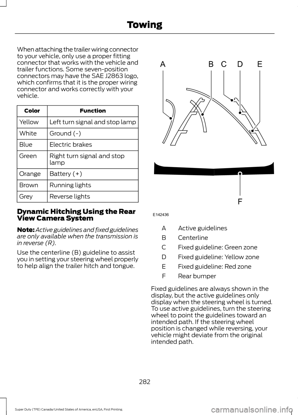
Dynamic Hitching Using the Rear
View Camera System
Note: Active guidelines and fixed guidelines
are only available when the transmission is
in reverse (R).
Use the centerline (B) guideline to assist
you in setting your steering wheel properly
to help align the trailer hitch and tongue. Active guidelines
A
Centerline
B
Fixed guideline: Green zone
C
Fixed guideline: Yellow zone
D
Fixed guideline: Red zone
E
Rear bumper
F
Fixed guidelines are always shown in the
display, but the active guidelines only
display when the steering wheel is turned.
To use active guidelines, turn the steering
wheel to point the guidelines toward an
intended path. If the steering wheel
position is changed while reversing, your
vehicle might deviate from the original
intended path.
282
Super Duty (TFE) Canada/United States of America, enUSA, First Printing TowingABCD
F
E
E142436
Page 288 of 636
Integrated Trailer Brake Controller
(If Equipped)
WARNINGS
The anti-lock brake system does not
control the trailer brakes.
Use the integrated trailer brake
controller to properly adjust the
trailer brakes and check all
connections before towing a trailer. Failure
to follow this instruction could result in the
loss of control of your vehicle, personal
injury or death. Note:
The integrated Ford brake controller
is compatible with trailers equipped with
electric-actuated drum brakes and
electric-over hydraulic brake systems.
Note: The integrated Ford brake controller
does not control hydraulic surge-style
brakes. When used properly, the trailer brake
controller assists in smooth and effective
trailer braking by powering the trailer
’s
electric or electric-over-hydraulic brakes
with a proportional output based on the
towing vehicle ’s brake pressure.
You can adjust the amount of initial trailer
brake output by selecting one of three
settings through the message center. Ford has tested the trailer brake controller
to be compatible with several major
brands of electric-over-hydraulic trailer
brakes. Contact an authorized dealer for
information on which brands you can use.
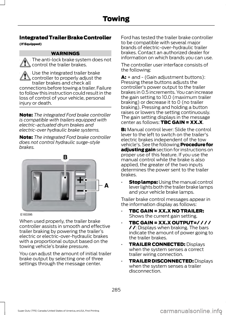
The controller user interface consists of
the following:
A: + and - (Gain adjustment buttons):
Pressing these buttons adjusts the
controller's power output to the trailer
brakes in 0.5 increments. You can increase
the gain setting to 10.0 (maximum trailer
braking) or decrease it to 0 (no trailer
braking). Pressing and holding a button
raises or lowers the setting continuously.
The gain setting displays in the message
center as follows:
TBC GAIN = XX.X.
B:
Manual control lever: Slide the control
lever to the left to switch on the trailer's
electric brakes independent of the tow
vehicle's. See the following Procedure for
adjusting gain section for instructions on
proper use of this feature. If you use the
manual control while the brake is also
applied, the greater of the two inputs
determines the power sent to the trailer
brakes.
• Stop lamps: Using the manual control
lever lights both the trailer brake lamps
and your vehicle brake lamps.
Trailer brake control messages appear in
the information display as follows:
• TBC GAIN = XX.X NO TRAILER:
Shows the current gain setting.
• TBC GAIN = XX.X OUTPUT=/ / / /
/ /
: Displays when braking. The bars
indicate the amount of power going to
the trailer brakes.
• TRAILER CONNECTED:
Displays
when the system senses a correct
trailer wiring connection.
• TRAILER DISCONNECTED: Displays
when the system senses a trailer
disconnection.
285
Super Duty (TFE) Canada/United States of America, enUSA, First Printing TowingE183395
Page 290 of 636
If this message displays, with no trailer
connected, the problem is with your vehicle
wiring or trailer brake controller. Contact
an authorized dealer.
If the message only displays with a trailer
connected, the problem is with the trailer
wiring. Consult your trailer dealer for
assistance. This can be a short to ground
(such as a chaffed wire), short to voltage
(such as a pulled pin on trailer emergency
breakaway battery) or the trailer brakes
may be drawing too much current.
Points to Remember
Note:
Do not attempt removal of the trailer
brake controller without consulting the
Workshop Manual. Damage to the unit may
result.
• Adjust gain setting before using the
trailer brake controller.
• Adjust gain setting, using the procedure
above, whenever road, weather, trailer
or vehicle loading conditions change
from when the gain was initially set.
• Only use the manual control lever for
proper adjustment of the gain during
trailer setup. Misuse, such as
application during trailer sway, could
cause instability of trailer or tow
vehicle.
• Avoid towing in adverse weather
conditions. The trailer brake controller
does not provide anti-lock control of
the trailer wheels. Trailer wheels can
lock up on slippery surfaces, resulting
in reduced stability of trailer and tow
vehicle.
• The trailer brake controller is equipped
with a feature that reduces output at
vehicle speeds below 11 mph (18 km/h)
so trailer and vehicle braking is not jerky
or harsh. This feature is only active
when applying the brakes using your
vehicle's brake pedal, not the
controller. •
The controller interacts with the brake
control system and powertrain control
system of your vehicle to provide the
best performance on different road
conditions.
• Your vehicle's brake system and the
trailer brake system work
independently of each other. Changing
the gain setting on the controller does
not affect the operation of your
vehicle's brakes.
• When you switch the engine off, the
controller output is disabled and the
display and module shut down.
Trailer Lamps WARNING
Never connect any trailer lamp wiring
to the vehicle's tail lamp wiring; this
may damage the electrical system
resulting in fire. Contact your authorized
dealer as soon as possible for assistance
in proper trailer tow wiring installation.
Additional electrical equipment may be
required. Trailer lamps are required on most towed
vehicles. Make sure all running lights, brake
lights, turn signals and hazard lights are
working.
Before Towing a Trailer
Practice turning, stopping and backing up
to get the feel of your vehicle-trailer
combination before starting on a trip.
When turning, make wider turns so the
trailer wheels clear curbs and other
obstacles.
287
Super Duty (TFE) Canada/United States of America, enUSA, First Printing Towing
Page 294 of 636
•
Fuel economy may decrease with lower
temperatures during the first 8– 10
miles (12 –16 kilometers) of driving.
• Driving on flat terrain offers improved
fuel economy as compared to driving
on hilly terrain.
• Transmissions give their best fuel
economy when operated in the top
cruise gear and with steady pressure
on the gas pedal.
• Four-wheel-drive operation (if
equipped) is less fuel efficient than
two-wheel-drive operation.
• Close the windows for high-speed
driving.
DRIVING THROUGH WATER WARNING
Do not drive through flowing or deep
water as you may lose control of your
vehicle.
Note:
Driving through standing water can
cause vehicle damage.
Note: Engine damage can occur if water
enters the air filter.
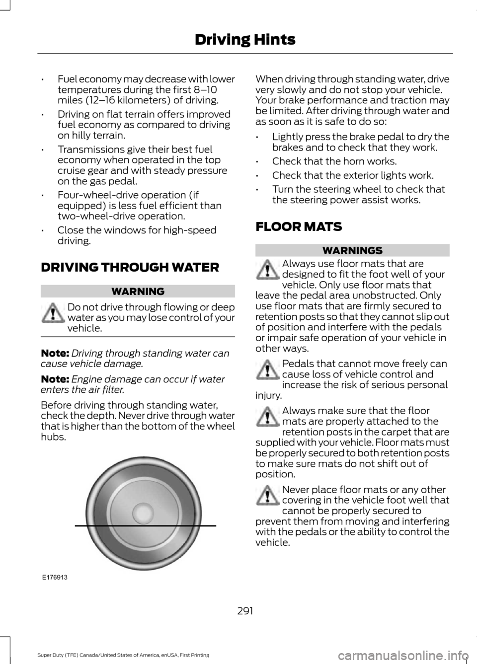
Before driving through standing water,
check the depth. Never drive through water
that is higher than the bottom of the wheel
hubs. When driving through standing water, drive
very slowly and do not stop your vehicle.
Your brake performance and traction may
be limited. After driving through water and
as soon as it is safe to do so:
•
Lightly press the brake pedal to dry the
brakes and to check that they work.
• Check that the horn works.
• Check that the exterior lights work.
• Turn the steering wheel to check that
the steering power assist works.
FLOOR MATS WARNINGS
Always use floor mats that are
designed to fit the foot well of your
vehicle. Only use floor mats that
leave the pedal area unobstructed. Only
use floor mats that are firmly secured to
retention posts so that they cannot slip out
of position and interfere with the pedals
or impair safe operation of your vehicle in
other ways. Pedals that cannot move freely can
cause loss of vehicle control and
increase the risk of serious personal
injury. Always make sure that the floor
mats are properly attached to the
retention posts in the carpet that are
supplied with your vehicle. Floor mats must
be properly secured to both retention posts
to make sure mats do not shift out of
position. Never place floor mats or any other
covering in the vehicle foot well that
cannot be properly secured to
prevent them from moving and interfering
with the pedals or the ability to control the
vehicle.
291
Super Duty (TFE) Canada/United States of America, enUSA, First Printing Driving HintsE176913
Page 400 of 636
12.
Turn the ignition off. If two short horn
beeps are heard, the reset procedure
was unsuccessful and you must
repeat it. If after repeating the
procedure and two short beeps are
heard when the ignition is turned to
off, seek assistance from your
authorized dealer.
13. Set all four tires to the recommended
air pressure as indicated on the
Safety Compliance Certification
Label (affixed to either the door hinge
pillar, door-latch post, or the door
edge that meets the door-latch post,
next to the driver's seating position)
or Tire Label located on the B-Pillar
or the edge of the driver's door.
Trailer Tire Pressure Monitoring
System (If Equipped)
Note: Additional equipment may be
required for your vehicle to support trailer
tire pressure monitoring. See your authorized
dealer for more information.
Note: The trailer tire pressure monitoring
system is not a substitute for proper tire
maintenance. It is your responsibility to
maintain correct tire pressures at all times.
Note: If a trailer tire is repaired, replaced or
broken down for service, the screw and valve
on the trailer tire pressure sensor should be
replaced. See your authorized dealer for
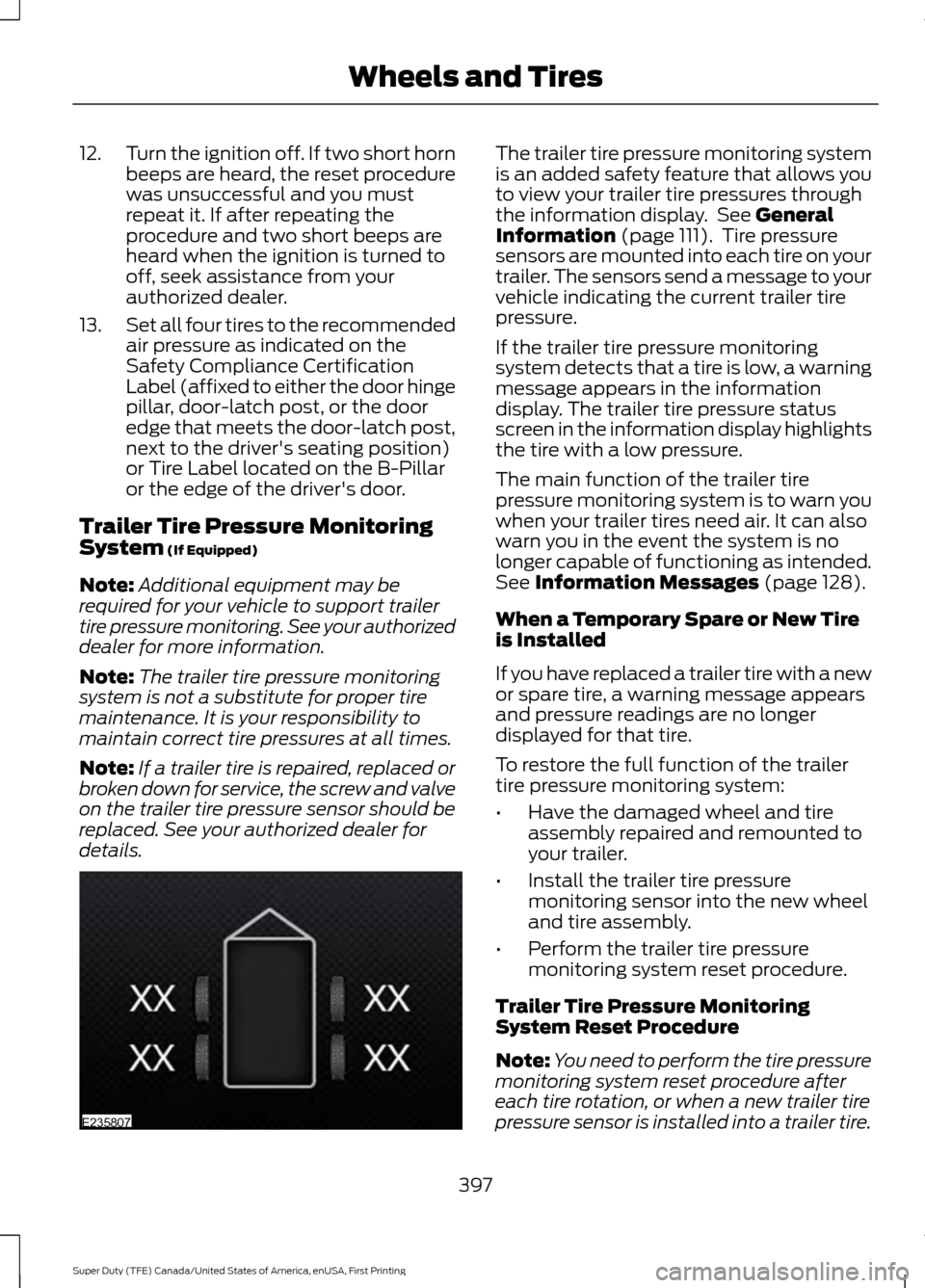
details. The trailer tire pressure monitoring system
is an added safety feature that allows you
to view your trailer tire pressures through
the information display. See
General
Information (page 111). Tire pressure
sensors are mounted into each tire on your
trailer. The sensors send a message to your
vehicle indicating the current trailer tire
pressure.
If the trailer tire pressure monitoring
system detects that a tire is low, a warning
message appears in the information
display. The trailer tire pressure status
screen in the information display highlights
the tire with a low pressure.
The main function of the trailer tire
pressure monitoring system is to warn you
when your trailer tires need air. It can also
warn you in the event the system is no
longer capable of functioning as intended.
See
Information Messages (page 128).
When a Temporary Spare or New Tire
is Installed
If you have replaced a trailer tire with a new
or spare tire, a warning message appears
and pressure readings are no longer
displayed for that tire.
To restore the full function of the trailer
tire pressure monitoring system:
• Have the damaged wheel and tire
assembly repaired and remounted to
your trailer.
• Install the trailer tire pressure
monitoring sensor into the new wheel
and tire assembly.
• Perform the trailer tire pressure
monitoring system reset procedure.
Trailer Tire Pressure Monitoring
System Reset Procedure
Note: You need to perform the tire pressure
monitoring system reset procedure after
each tire rotation, or when a new trailer tire
pressure sensor is installed into a trailer tire.
397
Super Duty (TFE) Canada/United States of America, enUSA, First Printing Wheels and TiresE235807
Page 464 of 636
Sending a Text Message
Note:
You can only send a text message to
one recipient at a time.
1. Select the send option when the desired selection highlights in the audio
display.
2. Select the confirmation option when the contact appears.
3. Press the OK button again to confirm when the system asks if you want to
send the message. A pre-defined
signature appears on each text
message. Note:
You can send text messages either
by choosing a contact from the phonebook
and selecting the text option from the audio
display or by replying to a received message
in the inbox.
Accessing Your Phone Settings
These are phone-dependent features. Your
phone settings allow you to access and
adjust features such as your ring tone and
text message notification, modify your
phonebook, and set up automatic
download.
1. Press the PHONE button.
2. Scroll until the phone settings option appears, and then press the OK button.
Scroll to select from the following options: Description and action
Menu Item
If this option is checked, the system uses the cellular phone
as the master when there is more than one cellular phone
paired to the system. This option can be changed for all
cellular phones (not only the active phone) using the
Bluetooth Devices menu.
Set as master
See the cellular phone name, provider name, cellular
phone number, and signal level. When done, press the left
arrow buttons to return to the phone status menu.
Phone status
Select which ringtone sounds during an incoming call (one
of the system's tones or your cellular phone's). If your
phone supports in-band ringing, your phone's ringtone
sounds when you choose the cellular phone ringtone
option.
Set ringtone
1. Press the
OK button to select and scroll to hear each
ringtone.
2. Press the
OK button to select a ringtone.
Have the option of hearing an audible tone to notify you
when a text message arrives. Press the
OK button to
switch the audible tone off or on.
Text msg notify
Modify the contents of your phonebook (such as add,
delete or download). Press the
OK button to select and
scroll between the choices in the phonebook preferences
table below.
Phonebook pref.
461
Super Duty (TFE) Canada/United States of America, enUSA, First Printing SYNC™
(If Equipped)
Page 520 of 636
Note: The heated steering wheel may remain on after remote starting the
vehicle, based on your remote start settings. The heated steering wheel may
also turn on when you start your vehicle, if it was on when you switched your
vehicle off.
Note:
For steering wheels with wood trim, the heating feature will not heat the
wheel between the 10 and 2 o'clock positions.
Defrost:
A pop up appears on the screen to display the defrost options.
C
MAX Defrost: Touch the button to maximize defrosting. Air flows through the
windshield vents, the fan automatically adjusts to the highest speed and the
driver and passenger temperatures are set to HI. You can use this setting to
defog or clear a thin covering of ice from the windshield. The heated rear window
also automatically turns on when you select MAX Defrost.
Defrost:
Distributes air through the windshield defroster vents and demister
vents.
AUTO:
Touch the button to switch on automatic operation. Select the desired
temperature using the temperature control. The system adjusts fan speed, air
distribution, air conditioning operation, and selects outside air or recirculated
air to heat or cool the vehicle in order to maintain the desired temperature.
D
Power:
Touch the button to switch the system on and off. Switching off the
climate control system prevents outside air from entering the vehicle.
E
DUAL:
This button lights up when the passenger controls are active. To switch
it off and link the passenger temperature to the driver temperature, touch the
DUAL button.
F
Note:
the passenger side temperature and the DUAL indication automatically
turn on when you or your passenger adjust the passenger temperature.
Passenger temperature:
Touch up or down to adjust the temperature.
G
Fan speed:
Touch up or down to increase or decrease the volume of air that
circulates in your vehicle.
H
Note:
You cannot adjust the fan speed when the system is set to AUTO or MAX
A/C.
A/C:
A pop-up appears on the screen to display the air conditioning options.
I
MAX A/C: Touch the button to activate and maximize cooling. The driver and
passenger temperatures are set to LO, recirculated air flows through the
instrument panel vents, air conditioning automatically turns on and the fan
automatically adjusts to the highest speed.
A/C:
Touch to switch the air conditioning on or off. Use A/C with recirculated
air to improve cooling performance and efficiency.
Note:
In certain conditions (for example, Max Defrost), the air conditioning
compressor may continue to operate even when you switch the air conditioning
A/C button off.
517
Super Duty (TFE) Canada/United States of America, enUSA, First Printing SYNC™ 3
(If Equipped)
Page 528 of 636
3D city models are complete 3D models
of entire city areas including navigable
roads, parks, rivers and rendered buildings.
3D landmarks and city models appear in
3D map mode only. Coverage of these
varies and improves with updated map
releases.
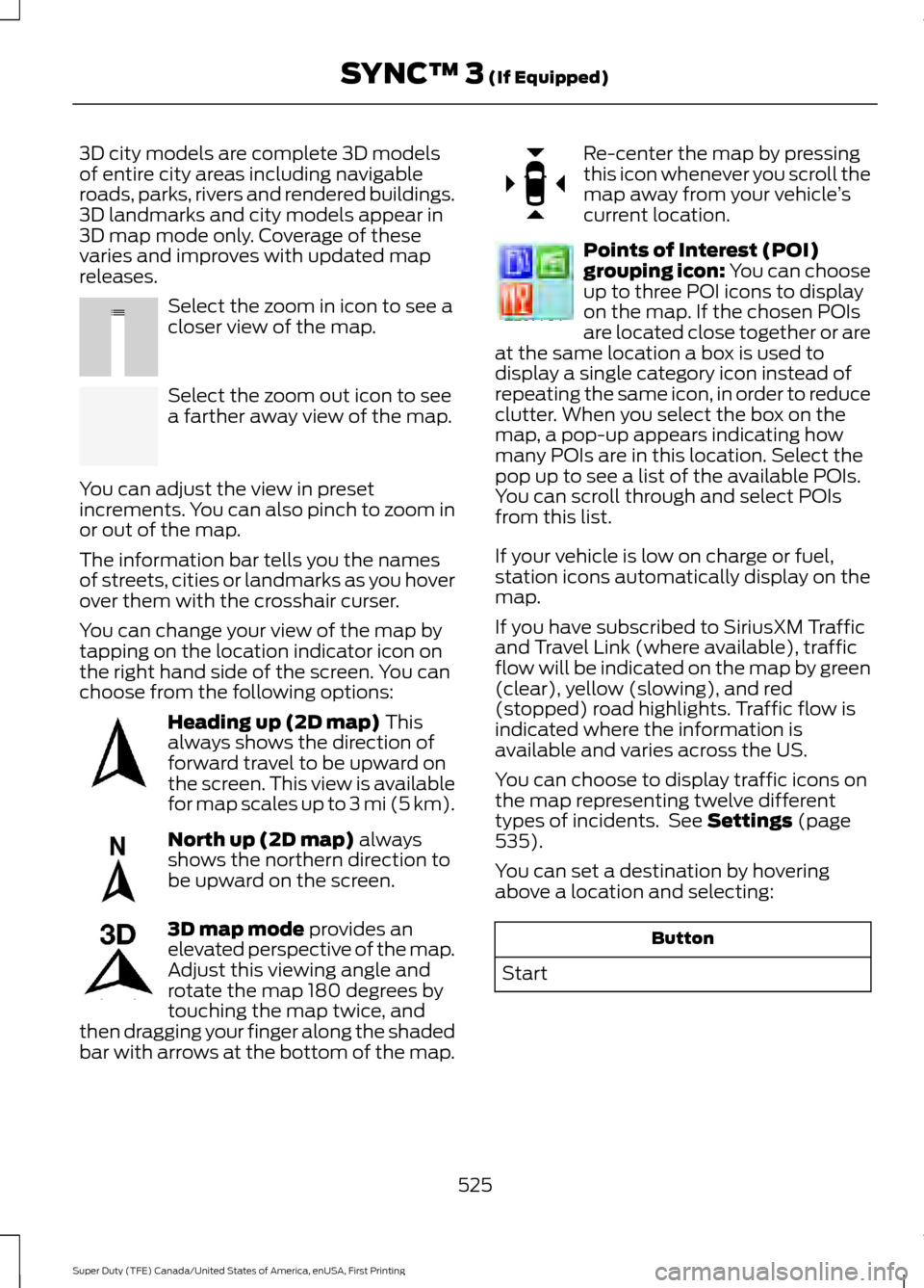
Select the zoom in icon to see a
closer view of the map.
Select the zoom out icon to see
a farther away view of the map.
You can adjust the view in preset
increments. You can also pinch to zoom in
or out of the map.
The information bar tells you the names
of streets, cities or landmarks as you hover
over them with the crosshair curser.
You can change your view of the map by
tapping on the location indicator icon on
the right hand side of the screen. You can
choose from the following options: Heading up (2D map) This
always shows the direction of
forward travel to be upward on
the screen. This view is available
for map scales up to
3 mi (5 km). North up (2D map)
always
shows the northern direction to
be upward on the screen. 3D map mode
provides an
elevated perspective of the map.
Adjust this viewing angle and
rotate the map 180 degrees by
touching the map twice, and
then dragging your finger along the shaded
bar with arrows at the bottom of the map. Re-center the map by pressing
this icon whenever you scroll the
map away from your vehicle
’s
current location. Points of Interest (POI)
grouping icon: You can choose
up to three POI icons to display
on the map. If the chosen POIs
are located close together or are
at the same location a box is used to
display a single category icon instead of
repeating the same icon, in order to reduce
clutter. When you select the box on the
map, a pop-up appears indicating how
many POIs are in this location. Select the
pop up to see a list of the available POIs.
You can scroll through and select POIs
from this list.
If your vehicle is low on charge or fuel,
station icons automatically display on the
map.
If you have subscribed to SiriusXM Traffic
and Travel Link (where available), traffic
flow will be indicated on the map by green
(clear), yellow (slowing), and red
(stopped) road highlights. Traffic flow is
indicated where the information is
available and varies across the US.
You can choose to display traffic icons on
the map representing twelve different
types of incidents. See
Settings (page
535).
You can set a destination by hovering
above a location and selecting: Button
Start
525
Super Duty (TFE) Canada/United States of America, enUSA, First Printing SYNC™ 3
(If Equipped)E207752 E207753 E207750 E207749 E207748 E207751 E207754