2017 FORD SUPER DUTY warning
[x] Cancel search: warningPage 400 of 636
12.
Turn the ignition off. If two short horn
beeps are heard, the reset procedure
was unsuccessful and you must
repeat it. If after repeating the
procedure and two short beeps are
heard when the ignition is turned to
off, seek assistance from your
authorized dealer.
13. Set all four tires to the recommended
air pressure as indicated on the
Safety Compliance Certification
Label (affixed to either the door hinge
pillar, door-latch post, or the door
edge that meets the door-latch post,
next to the driver's seating position)
or Tire Label located on the B-Pillar
or the edge of the driver's door.
Trailer Tire Pressure Monitoring
System (If Equipped)
Note: Additional equipment may be
required for your vehicle to support trailer
tire pressure monitoring. See your authorized
dealer for more information.
Note: The trailer tire pressure monitoring
system is not a substitute for proper tire
maintenance. It is your responsibility to
maintain correct tire pressures at all times.
Note: If a trailer tire is repaired, replaced or
broken down for service, the screw and valve
on the trailer tire pressure sensor should be
replaced. See your authorized dealer for
details. The trailer tire pressure monitoring system
is an added safety feature that allows you
to view your trailer tire pressures through
the information display. See
General
Information (page 111). Tire pressure
sensors are mounted into each tire on your
trailer. The sensors send a message to your
vehicle indicating the current trailer tire
pressure.
If the trailer tire pressure monitoring
system detects that a tire is low, a warning
message appears in the information
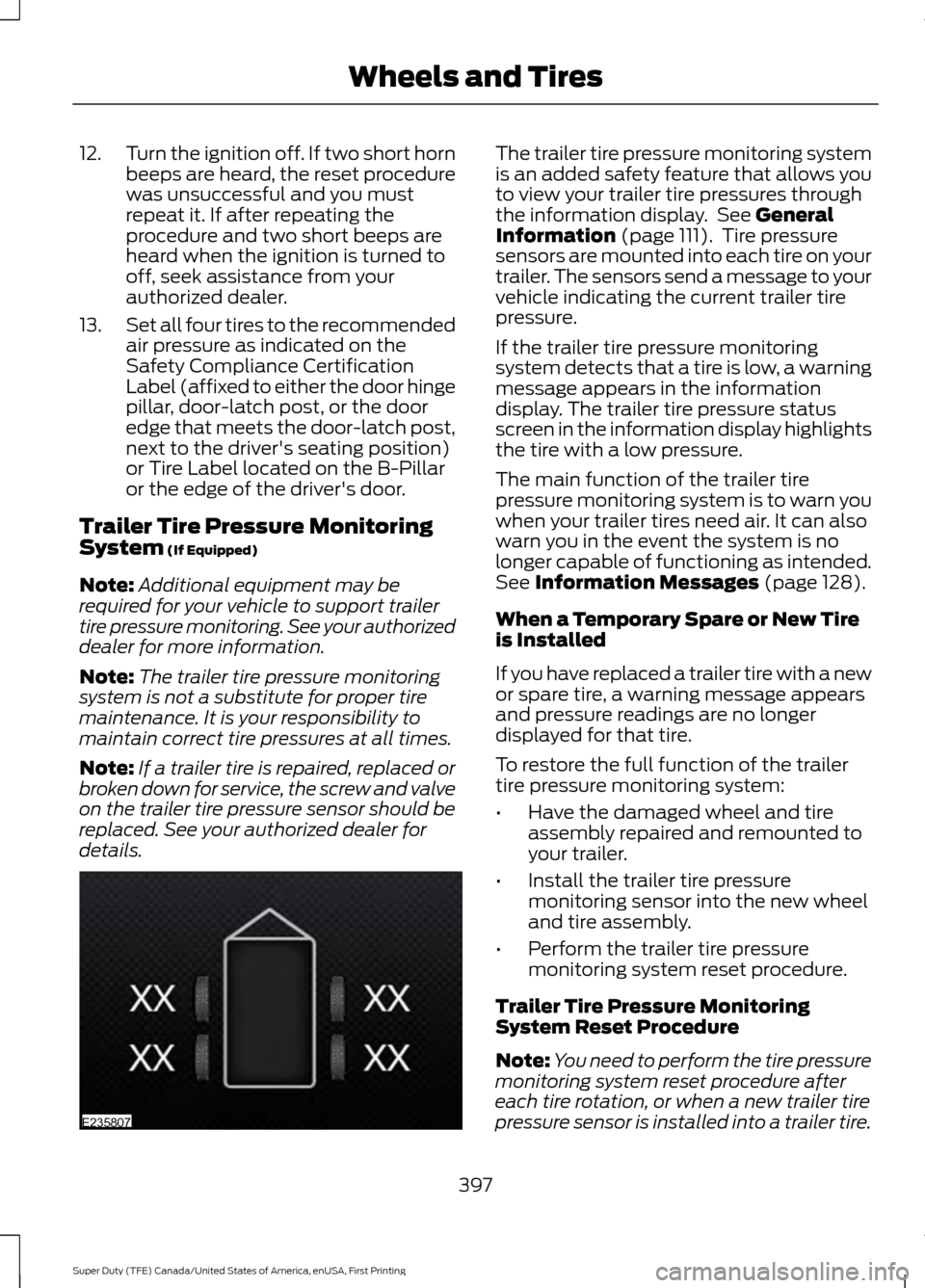
display. The trailer tire pressure status
screen in the information display highlights
the tire with a low pressure.
The main function of the trailer tire
pressure monitoring system is to warn you
when your trailer tires need air. It can also
warn you in the event the system is no
longer capable of functioning as intended.
See
Information Messages (page 128).
When a Temporary Spare or New Tire
is Installed
If you have replaced a trailer tire with a new
or spare tire, a warning message appears
and pressure readings are no longer
displayed for that tire.
To restore the full function of the trailer
tire pressure monitoring system:
• Have the damaged wheel and tire
assembly repaired and remounted to
your trailer.
• Install the trailer tire pressure
monitoring sensor into the new wheel
and tire assembly.
• Perform the trailer tire pressure
monitoring system reset procedure.
Trailer Tire Pressure Monitoring
System Reset Procedure
Note: You need to perform the tire pressure
monitoring system reset procedure after
each tire rotation, or when a new trailer tire
pressure sensor is installed into a trailer tire.
397
Super Duty (TFE) Canada/United States of America, enUSA, First Printing Wheels and TiresE235807
Page 401 of 636
The trailer tire pressure monitoring system
can be reset through the menu in the
information display. See General
Information (page 111). Performing the
trailer setup process also resets the trailer
tire pressure monitoring system.
CHANGING A ROAD WHEEL WARNINGS
The use of tire sealant may damage
your tire pressure monitoring system
and should only be used in roadside
emergencies. If you must use a sealant, the
Ford Tire Mobility Kit sealant should be
used. The tire pressure monitoring system
sensor and valve stem on the wheel must
be replaced by an authorized dealer after
use of the sealant. If the tire pressure monitor sensor
becomes damaged, it will no longer
function. See
Tire Pressure
Monitoring System (page 390). Note:
If your vehicle is equipped with the
tire pressure monitoring system, the
indicator light will illuminate when the spare
tire is in use. To restore the full function of
the monitoring system, all road wheels
equipped with tire pressure monitoring
sensors must be mounted on the vehicle.
If you get a flat tire while driving, do not
apply the brake heavily. Instead, gradually
decrease your speed. Hold the steering
wheel firmly and slowly move to a safe
place on the side of the road. If your vehicle is equipped with the tire
pressure monitoring system, have a flat
serviced by an authorized dealer in order
to prevent damage to the system sensors.
See
Tire Pressure Monitoring System
(page 390). Replace the spare tire with a
road tire as soon as possible. During
repairing or replacing of the flat tire, have
the authorized dealer inspect the system
sensor for damage.
Dissimilar Spare Wheel and Tire
Assembly Information WARNING
Failure to follow these guidelines
could result in an increased risk of
loss of vehicle control, injury or death.
If you have a dissimilar spare wheel and
tire, then it is intended for temporary use
only. This means that if you need to use it,
you should replace it as soon as possible
with a road wheel and tire assembly that
is the same size and type as the road tires
and wheels that were originally provided
by Ford. If the dissimilar spare tire or wheel
is damaged, it should be replaced rather
than repaired.
A dissimilar spare wheel and tire assembly
is defined as a spare wheel and tire
assembly that is different in brand, size or
appearance from the road tires and wheels
and can be one of three types:
1.
T-type mini-spare:
This spare tire
begins with the letter T for tire size and
may have Temporary Use Only molded in
the sidewall.
2. Full-size dissimilar spare with label
on wheel:
This spare tire has a label on
the wheel that states: THIS WHEEL AND
TIRE ASSEMBLY FOR TEMPORARY USE
ONLY
When driving with one of the dissimilar
spare tires listed above, do not:
398
Super Duty (TFE) Canada/United States of America, enUSA, First Printing Wheels and Tires
Page 404 of 636
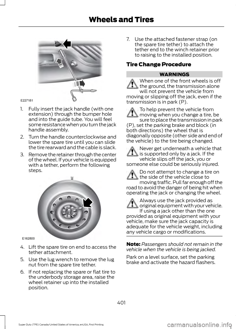
1. Fully insert the jack handle (with one
extension) through the bumper hole
and into the guide tube. You will feel
some resistance when you turn the jack
handle assembly.
2. Turn the handle counterclockwise and
lower the spare tire until you can slide
the tire rearward and the cable is slack.
3. Remove the retainer through the center
of the wheel. If your vehicle is equipped
with a tether, perform the following
steps. 4.
Lift the spare tire on end to access the
tether attachment.
5. Use the lug wrench to remove the lug nut from the spare tire tether.
6. If not replacing the spare or flat tire to the underbody storage area, raise the
wheel retainer up into the installed
position. 7. Use the attached fastener strap (on
the spare tire tether) to attach the
tether end to the winch retainer prior
to raising to the installed position.
Tire Change Procedure WARNINGS
When one of the front wheels is off
the ground, the transmission alone
will not prevent the vehicle from
moving or slipping off the jack, even if the
transmission is in park (P). To help prevent the vehicle from
moving when you change a tire, be
sure to place the transmission in park
(P), set the parking brake and block (in
both directions) the wheel that is
diagonally opposite (other side and end of
the vehicle) to the tire being changed. Never get underneath a vehicle that
is supported only by a jack. If the
vehicle slips off the jack, you or
someone else could be seriously injured. Do not attempt to change a tire on
the side of the vehicle close to
moving traffic. Pull far enough off the
road to avoid the danger of being hit when
operating the jack or changing the wheel. Always use the jack provided as
original equipment with your vehicle.
If using a jack other than the one
provided as original equipment with your
vehicle, make sure the jack capacity is
adequate for the vehicle weight, including
any vehicle cargo or modifications. Note:
Passengers should not remain in the
vehicle when the vehicle is being jacked.
Park on a level surface, set the parking
brake and activate the hazard flashers.
401
Super Duty (TFE) Canada/United States of America, enUSA, First Printing Wheels and TiresE227181 E162800
Page 412 of 636
7.
Repeat this tightness check procedure
when servicing the spare tire pressure
(every six months, per scheduled
maintenance information), or at any
time that the spare tire is disturbed through service of other components.
8. If removed, install the spare tire lock into the bumper drive tube with the
spare tire lock key and jack handle.
TECHNICAL SPECIFICATIONS
Wheel Lug Nut Torque Specifications WARNING
When a wheel is installed, always remove any corrosion, dirt or foreign materials
present on the mounting surfaces of the wheel or the surface of the wheel hub,
brake drum or brake disc that contacts the wheel. Make sure that any fasteners
that attach the rotor to the hub are secured so they do not interfere with the mounting
surfaces of the wheel. Installing wheels without correct metal-to-metal contact at the
wheel mounting surfaces can cause the wheel nuts to loosen and the wheel to come off
while the vehicle is in motion, resulting in loss of control. lb.ft (Nm)
Bolt size
165 lb.ft (224 Nm)
M14 x 1.5
* Torque specifications are for nut and bolt threads free of dirt and rust. Use only Ford
recommended replacement fasteners.
On vehicles equipped with single rear wheels, retighten the lug nuts to the specified torque
at 100 miles (160 kilometers) after any wheel disturbance (such as tire rotation, changing
a flat tire, wheel removal).
On vehicles equipped with dual rear wheels, retighten the wheel lug nuts to the specified
torque at 100 miles (160 kilometers), and again at 500 miles (800 kilometers) of new
vehicle operation and after any wheel disturbance (such as tire rotation, changing a flat
tire, wheel removal).
It is important to follow the proper wheel mounting and lug nut torque procedures.
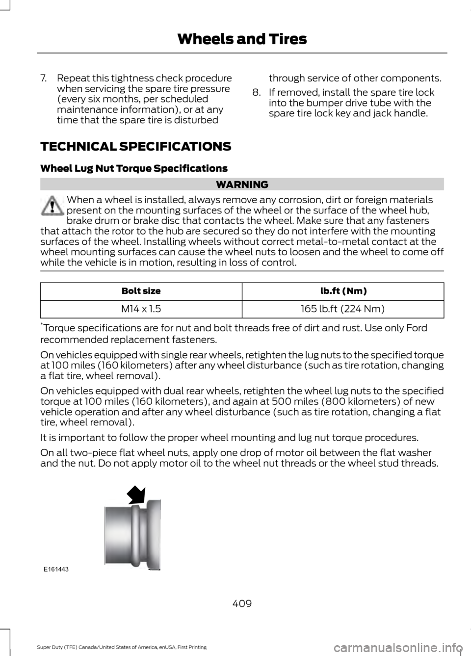
On all two-piece flat wheel nuts, apply one drop of motor oil between the flat washer
and the nut. Do not apply motor oil to the wheel nut threads or the wheel stud threads. 409
Super Duty (TFE) Canada/United States of America, enUSA, First Printing Wheels and TiresE161443
Page 421 of 636
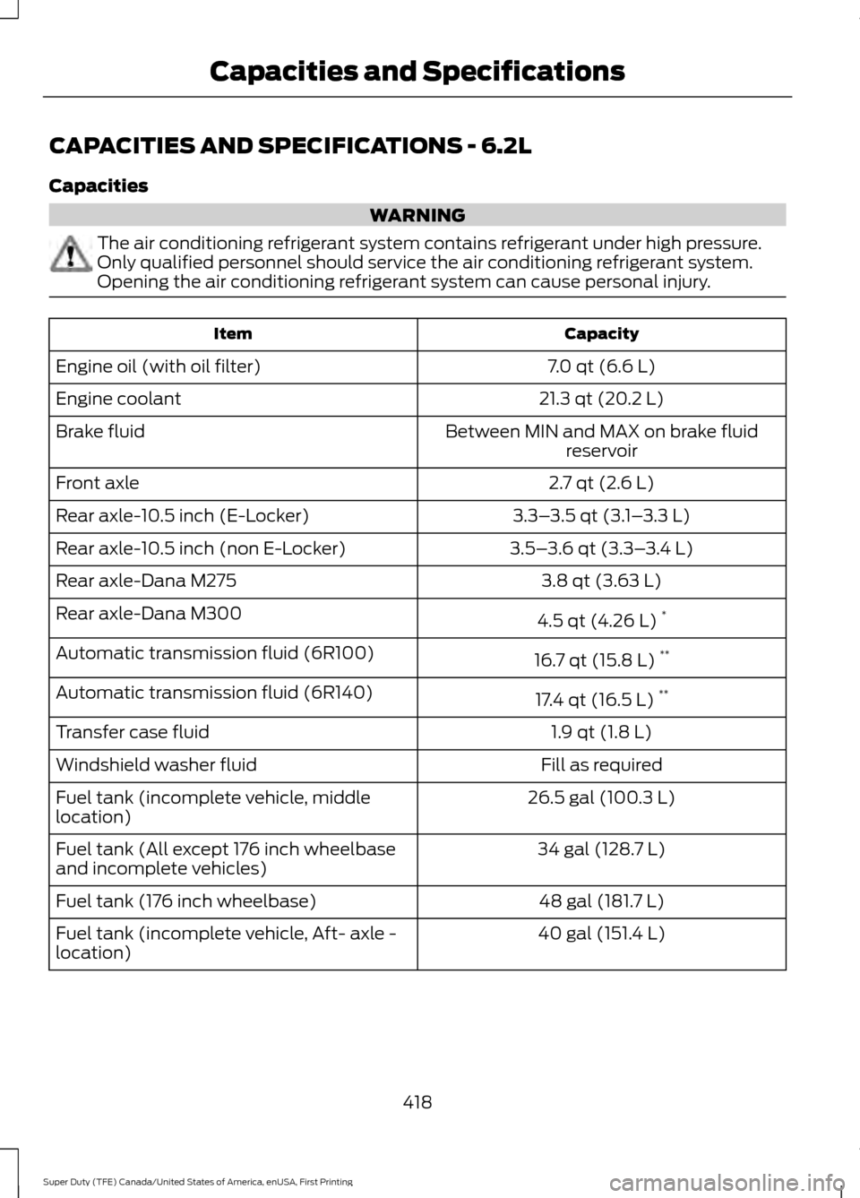
CAPACITIES AND SPECIFICATIONS - 6.2L
Capacities
WARNING
The air conditioning refrigerant system contains refrigerant under high pressure.
Only qualified personnel should service the air conditioning refrigerant system.
Opening the air conditioning refrigerant system can cause personal injury.
Capacity
Item
7.0 qt (6.6 L)
Engine oil (with oil filter)
21.3 qt (20.2 L)
Engine coolant
Between MIN and MAX on brake fluidreservoir
Brake fluid
2.7 qt (2.6 L)
Front axle
3.3–3.5 qt (3.1– 3.3 L)
Rear axle-10.5 inch (E-Locker)
3.5–3.6 qt (3.3– 3.4 L)
Rear axle-10.5 inch (non E-Locker)
3.8 qt (3.63 L)
Rear axle-Dana M275
4.5 qt (4.26 L)*
Rear axle-Dana M300
16.7 qt (15.8 L)**
Automatic transmission fluid (6R100)
17.4 qt (16.5 L)**
Automatic transmission fluid (6R140)
1.9 qt (1.8 L)
Transfer case fluid
Fill as required
Windshield washer fluid
26.5 gal (100.3 L)
Fuel tank (incomplete vehicle, middle
location)
34 gal (128.7 L)
Fuel tank (All except 176 inch wheelbase
and incomplete vehicles)
48 gal (181.7 L)
Fuel tank (176 inch wheelbase)
40 gal (151.4 L)
Fuel tank (incomplete vehicle, Aft- axle -
location)
418
Super Duty (TFE) Canada/United States of America, enUSA, First Printing Capacities and Specifications
Page 425 of 636
If you use oil and fluids that do not meet
the defined specification and viscosity
grade, this may lead to:
•
Component damage which is not
covered by the vehicle warranty.
• Longer engine cranking periods.
• Increased emission levels.
• Reduced engine performance.
• Reduced fuel economy.
• Degraded brake performance.
We recommend Motorcraft® motor oil for
your vehicle. If Motorcraft® oil is not
available, use motor oils of the
recommended viscosity grade that meet
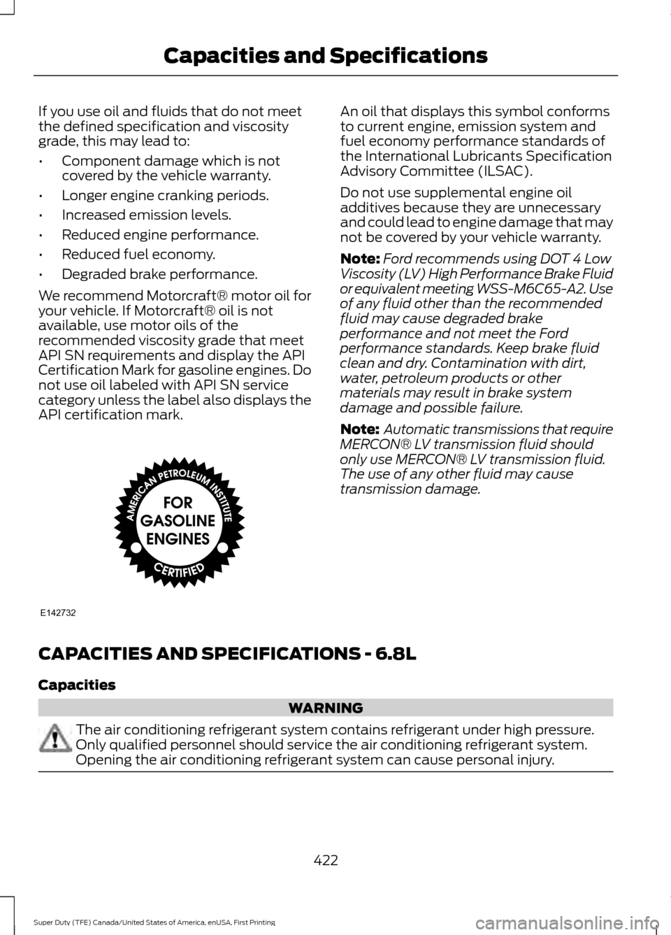
API SN requirements and display the API
Certification Mark for gasoline engines. Do
not use oil labeled with API SN service
category unless the label also displays the
API certification mark. An oil that displays this symbol conforms
to current engine, emission system and
fuel economy performance standards of
the International Lubricants Specification
Advisory Committee (ILSAC).
Do not use supplemental engine oil
additives because they are unnecessary
and could lead to engine damage that may
not be covered by your vehicle warranty.
Note:
Ford recommends using DOT 4 Low
Viscosity (LV) High Performance Brake Fluid
or equivalent meeting WSS-M6C65-A2. Use
of any fluid other than the recommended
fluid may cause degraded brake
performance and not meet the Ford
performance standards. Keep brake fluid
clean and dry. Contamination with dirt,
water, petroleum products or other
materials may result in brake system
damage and possible failure.
Note: Automatic transmissions that require
MERCON® LV transmission fluid should
only use MERCON® LV transmission fluid.
The use of any other fluid may cause
transmission damage.
CAPACITIES AND SPECIFICATIONS - 6.8L
Capacities WARNING
The air conditioning refrigerant system contains refrigerant under high pressure.
Only qualified personnel should service the air conditioning refrigerant system.
Opening the air conditioning refrigerant system can cause personal injury.
422
Super Duty (TFE) Canada/United States of America, enUSA, First Printing Capacities and SpecificationsE142732
Page 431 of 636
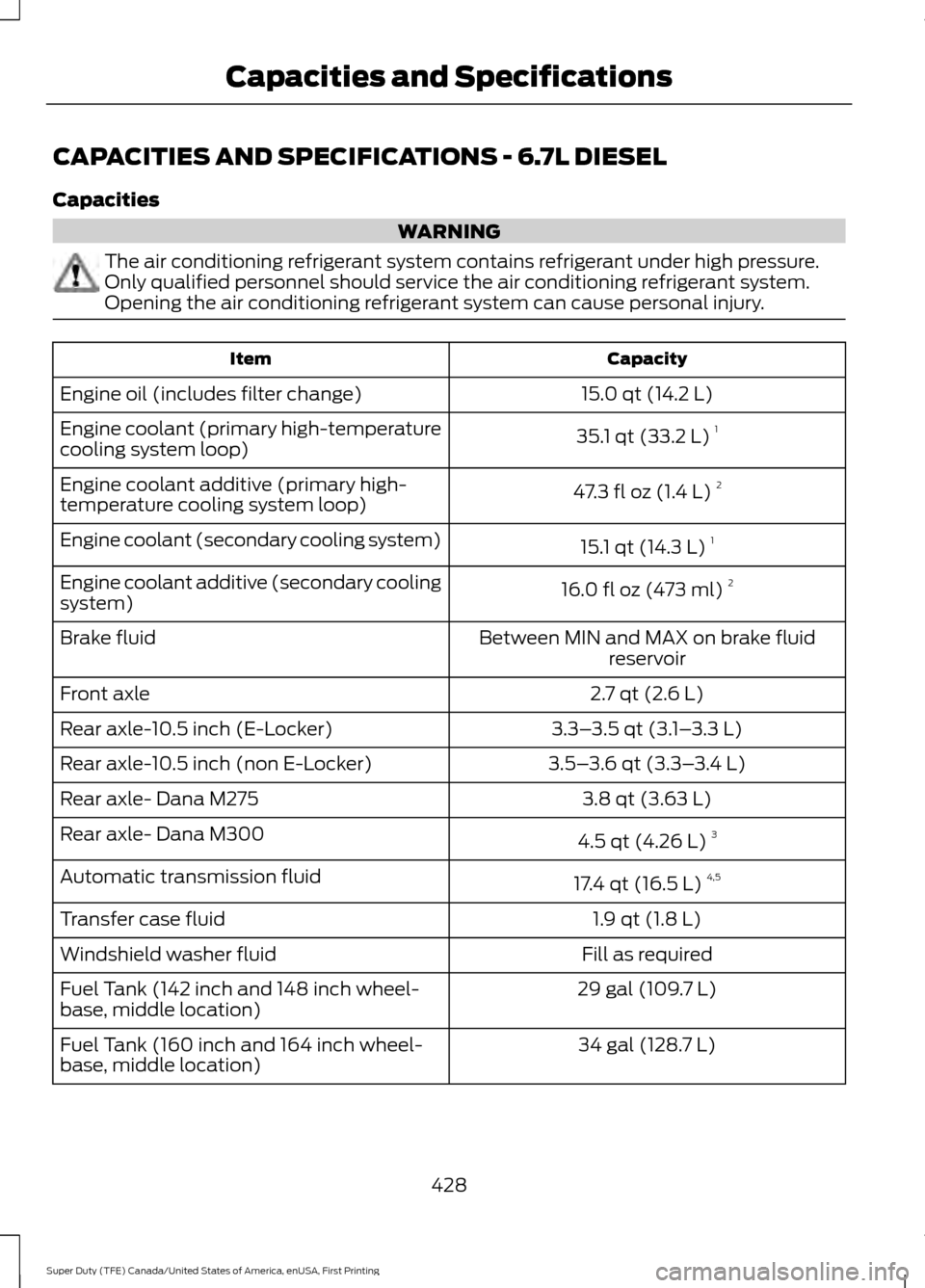
CAPACITIES AND SPECIFICATIONS - 6.7L DIESEL
Capacities
WARNING
The air conditioning refrigerant system contains refrigerant under high pressure.
Only qualified personnel should service the air conditioning refrigerant system.
Opening the air conditioning refrigerant system can cause personal injury.
Capacity
Item
15.0 qt (14.2 L)
Engine oil (includes filter change)
35.1 qt (33.2 L)1
Engine coolant (primary high-temperature
cooling system loop)
47.3 fl oz (1.4 L)2
Engine coolant additive (primary high-
temperature cooling system loop)
15.1 qt (14.3 L)1
Engine coolant (secondary cooling system)
16.0 fl oz (473 ml)2
Engine coolant additive (secondary cooling
system)
Between MIN and MAX on brake fluidreservoir
Brake fluid
2.7 qt (2.6 L)
Front axle
3.3–3.5 qt (3.1– 3.3 L)
Rear axle-10.5 inch (E-Locker)
3.5–3.6 qt (3.3– 3.4 L)
Rear axle-10.5 inch (non E-Locker)
3.8 qt (3.63 L)
Rear axle- Dana M275
4.5 qt (4.26 L)3
Rear axle- Dana M300
17.4 qt (16.5 L)4,5
Automatic transmission fluid
1.9 qt (1.8 L)
Transfer case fluid
Fill as required
Windshield washer fluid
29 gal (109.7 L)
Fuel Tank (142 inch and 148 inch wheel-
base, middle location)
34 gal (128.7 L)
Fuel Tank (160 inch and 164 inch wheel-
base, middle location)
428
Super Duty (TFE) Canada/United States of America, enUSA, First Printing Capacities and Specifications
Page 439 of 636
•
MP3 and WMA folder mode represents
a folder structure consisting of one
level of folders. The CD player numbers
all MP3 and WMA tracks on the disc
(noted by the MP3 or WMA file
extension) and all folders containing
MP3 and WMA files, from F001 (folder)
T001 (track) to F253 T255.
• Creating discs with only one level of
folders helps with navigation through
the disc files.
If you are burning your own MP3 and WMA
discs, it is important to understand how
the system reads the structures you create.
While various files may be present (files
with extensions other than MP3 and
WMA), only files with the MP3 and WMA
extension are played; other files are
ignored by the system. This enables you to
use the same MP3 and WMA disc for a
variety of tasks on your work computer,
home computer and your in-vehicle
system. In track mode, the system displays and
plays the structure as if it were only one
level deep (all MP3 and WMA files play,
regardless of being in a specific folder). In
folder mode, the system only plays the
MP3 and WMA files in the current folder.
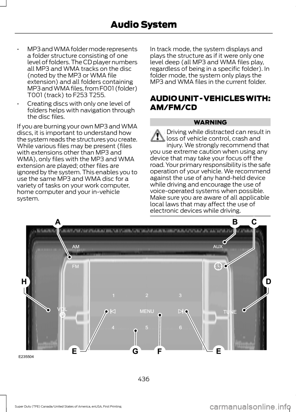
AUDIO UNIT - VEHICLES WITH:
AM/FM/CD WARNING
Driving while distracted can result in
loss of vehicle control, crash and
injury. We strongly recommend that
you use extreme caution when using any
device that may take your focus off the
road. Your primary responsibility is the safe
operation of your vehicle. We recommend
against the use of any hand-held device
while driving and encourage the use of
voice-operated systems when possible.
Make sure you are aware of all applicable
local laws that may affect the use of
electronic devices while driving. 436
Super Duty (TFE) Canada/United States of America, enUSA, First Printing Audio SystemE235504