Page 217 of 382

CHANGING THE ENGINE-
MOUNTED AND DIESEL FUEL
CONDITIONER MODULE FUEL
FILTERS
WARNING
Do not dispose of fuel in the
household refuse or the public
sewage system. Use an authorized
waste disposal facility. Your vehicle has two fuel filters. The first
filter mounts on top of the engine on the
left-hand side. The second filter is inside
the diesel fuel conditioner module. The
module is mounted between the outboard
side of the fuel tank and the frame rail.
Note:
The module is at the front of the fuel
tank or at the front of the aft-axle fuel tank
on some models.
Regular fuel filter changes are an
important part of engine maintenance;
failing to keep with the scheduled
maintenance could lead to engine
performance issues and fuel injection
system damage. See Scheduled
Maintenance (page 316).
Use only recommended service parts
conforming to specifications. See
Motorcraft Parts
(page 255).
Note: Using fuel that has high levels of
impurities may require more frequent filter
replacements than the service interval
specifies.
Diesel Fuel Conditioner Module
Filter
Removal
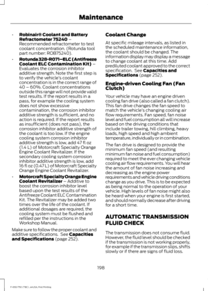
1. Access the underside of your vehicle. 2. The diesel fuel conditioner module is
on the left-hand frame rail.
214
F-650/750 (TBC) , enUSA, First Printing MaintenanceE226475
2
Page 218 of 382
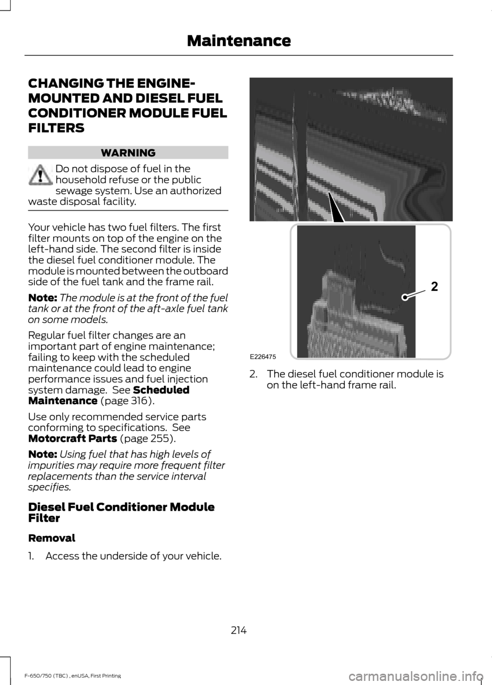
3. Drain the diesel fuel conditioner
module. Turn the drain plug
counterclockwise until it stops. Do not
use any tools to loosen the drain plug.
Drain the filter, approximately 0.5 gal
(2 L), into an appropriate container. Do
not re-use the fuel drained from the
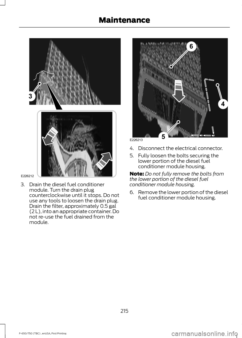
module. 4. Disconnect the electrical connector.
5. Fully loosen the bolts securing the
lower portion of the diesel fuel
conditioner module housing.
Note: Do not fully remove the bolts from
the lower portion of the diesel fuel
conditioner module housing.
6. Remove the lower portion of the diesel
fuel conditioner module housing.
215
F-650/750 (TBC) , enUSA, First Printing Maintenance3
E226212 4
5
6
E226213
Page 219 of 382

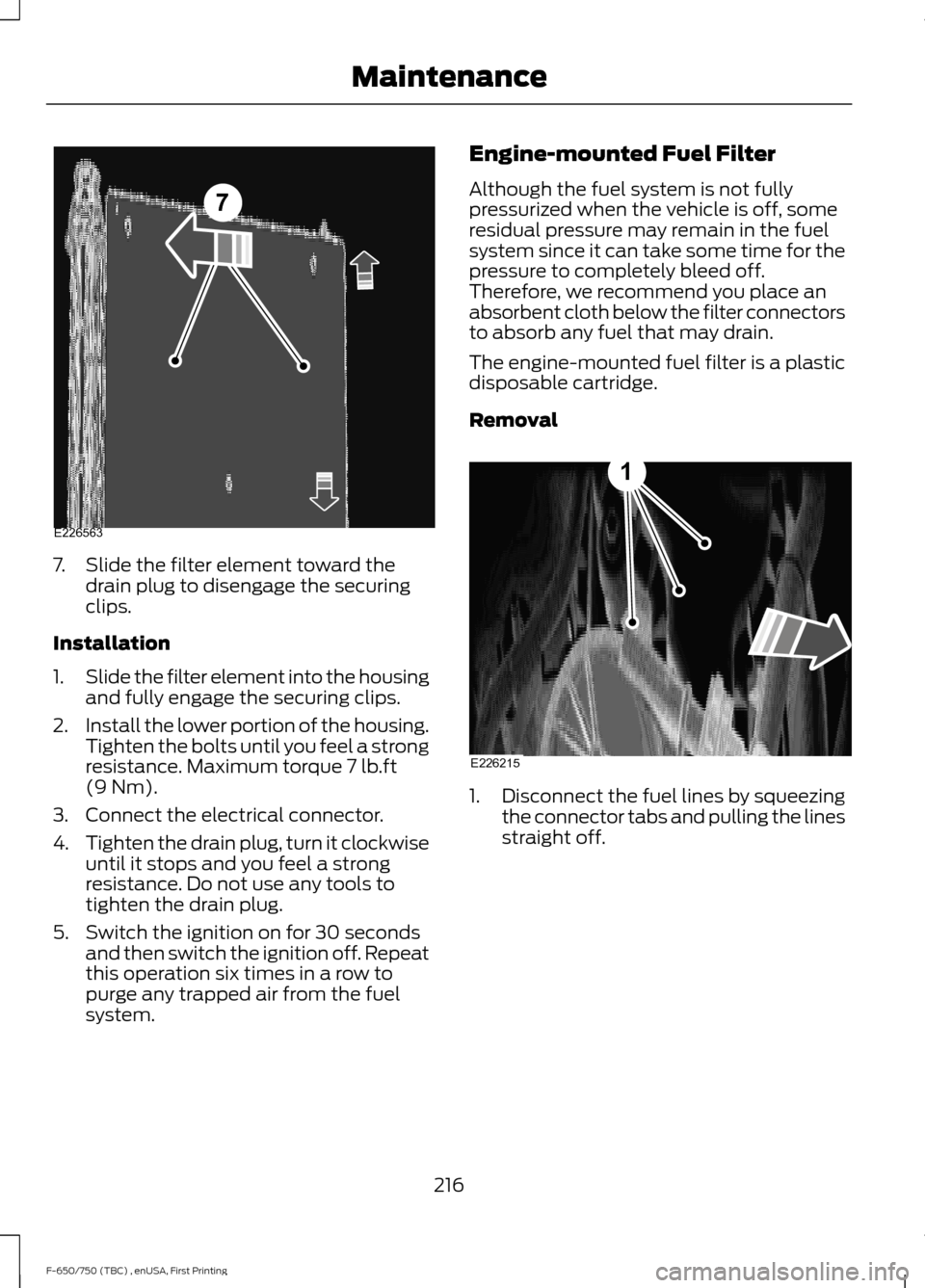
7. Slide the filter element toward the
drain plug to disengage the securing
clips.
Installation
1. Slide the filter element into the housing
and fully engage the securing clips.
2. Install the lower portion of the housing.
Tighten the bolts until you feel a strong
resistance. Maximum torque 7 lb.ft
(9 Nm).
3. Connect the electrical connector.
4. Tighten the drain plug, turn it clockwise
until it stops and you feel a strong
resistance. Do not use any tools to
tighten the drain plug.
5. Switch the ignition on for 30 seconds and then switch the ignition off. Repeat
this operation six times in a row to
purge any trapped air from the fuel
system. Engine-mounted Fuel Filter
Although the fuel system is not fully
pressurized when the vehicle is off, some
residual pressure may remain in the fuel
system since it can take some time for the
pressure to completely bleed off.
Therefore, we recommend you place an
absorbent cloth below the filter connectors
to absorb any fuel that may drain.
The engine-mounted fuel filter is a plastic
disposable cartridge.
Removal
1.
Disconnect the fuel lines by squeezing
the connector tabs and pulling the lines
straight off.
216
F-650/750 (TBC) , enUSA, First Printing Maintenance7
E226563 E226215
1
Page 220 of 382

2.
Rotate the filter fully counterclockwise
until the peg is at the far end of the slot.
3. Pull the filter straight up from the bracket and discard the filter.
Installation
1. Install the new filter into the filter bracket. Turn the filter clockwise to
lock it in place.
2. Reconnect the fuel lines.
3. Switch the ignition on for 30 seconds and then switch the ignition off. Repeat
this operation six times in a row to
purge any trapped air from the fuel
system.
ELECTRICAL SYSTEM
INSPECTION
Periodically inspect electrical connectors
on the outside of the cab and on the engine
and frame for corrosion and tightness.
Exposed terminals, such as the fuel sender,
cranking motor, alternator and
feed-through studs, should be cleaned and re-coated with a lubricant sealing grease
such as Motorcraft Silicone Brake Caliper
Grease and Dielectric Compound XG-3, or
equivalent. This should include the ground
cable connector for batteries, engine and
cab as well as the jump-starting stud.
Accessory Feed Connections
Vehicle electrical systems are complex and
often include powertrain components,
such as engine and transmission controls,
instrument panels and ABS. While most
systems operate on battery voltage (12
volts), some systems can be as high as 90
volts or as low as five volts. See the
Electrical Circuit Diagram Manuals,
available from your vehicle
’s manufacturer,
to make sure that any extra body lights and
accessory connections to circuits are both
appropriate and not overloaded. Do not
make modifications to any vehicle control
system without first contacting an
authorized dealer.
AIR INDUCTION SYSTEM
INSPECTION WARNING
When performing maintenance to
any turbocharged engine with engine
air inlet piping disconnected, keep
loose clothing, jewelry and long hair away
from the engine air inlet piping. A
turbocharger compressor air inlet
protective shield should be installed over
the turbocharger air inlet to reduce the risk
of personal injury or death. Perform a complete inspection of the air
induction system annually.
217
F-650/750 (TBC) , enUSA, First Printing MaintenanceE226214
2
3
Page 221 of 382

In areas where road salt is used,
disassemble the joints of each aluminum
component and inspect for salt build-up
and presence of chlorine that can cause
aluminum particles to flake off and enter
the engine combustion chambers. If
evidence of corrosion is found (usually at
the pipe connections), use a wire brush to
clean the inside of the pipes and inside the
rubber hoses.
If pitting is evident at the joint ends of the
intake pipes, use Motorcraft Silicone
Gasket and Sealant TA-30 to seal the
joints. Make sure no excess material, which
can pull into the engine, is on the inside of
the pipes. If the service condition of the
pipes, hoses or clamps is questionable,
replace the defective part(s).
Make sure to clean all dust and debris out
of the pipes and couplings with a clean,
damp rag before reassembly.
Chassis-mounted Charge Air
Cooler
Visually inspect the core assembly for
debris and clogging of external fins with
the engine off.
Before engine operation, remove any debris
blocking the core.
•
Turbocharger-to-charge air cooler.
• Charge air cooler-to-intake manifold
pipe.
• Mounting bracket.
• Chassis-mounted charge air cooler
core.
Inspect air intake piping:
• Check for accumulation of salt
deposits (where applicable). If present,
disassemble and clean the complete
air intake piping system. If pitting is
evident on the intake piping, use
Motorcraft Silicone Gasket and Sealant
TA-30 to seal joints against leakage.
• Check for loose hoses and clamps. •
Check for ruptured or collapsed hoses.
• Check air cleaner housing for cracks.
EXHAUST SYSTEM
INSPECTION
Note: If your vehicle is equipped with a
catalytic converter or muffler, do not blend
waste oil with diesel fuel. Operate only on
ultra-low sulfur (less than 15 parts per
million sulfur) diesel fuel with a cetane
value of 45 or higher.
If your diesel engine is equipped with a
catalytic converter, it is important to review
the maintenance schedule to make sure
proper functioning of the catalytic
converter. Also, take precautions not to
damage the catalytic converter when
servicing your engine or storing your
vehicle.
218
F-650/750 (TBC) , enUSA, First Printing Maintenance
Page 222 of 382

BRAKE SYSTEM INSPECTION
WARNING
Always wear a respirator approved
by the National Institute of
Occupational Studies of Health
(NIOSH) or Mine Safety and Appliance
(MSA) during all brake service procedures.
Wear the respirator from removal of the
wheels through assembly.
Never use compressed air or dry brushing
to clean brake parts or assemblies.
Clean brake parts and assemblies in open
air. During assembly, carefully place all
parts on the floor to avoid getting dust in
the air. Use an industrial vacuum cleaner
with a HEPA filter system to clean dust
from the brake drums, backing plates and
other brake parts. After using the vacuum,
remove any remaining dust with a rag
soaked in water and wrung until nearly dry.
Never use compressed air or dry sweeping
to clean the work area. Use an industrial
vacuum cleaner with a HEPA filter system
and rags soaked in water and wrung until
nearly dry. Dispose of used rags with care
to avoid getting dust in the air. Use an
approved respirator when emptying
vacuum cleaners and handling used rags.
Worker clean-up: Wash your hands before
eating, drinking or smoking. Vacuum your
work clothes after use and then launder
them separately, without shaking them, to
prevent fiber dust getting into the air. Your vehicle is equipped with
non-asbestos brake linings. However,
exposure to excessive amounts of brake
material (whether asbestos or
non-asbestos, fiberglass, mineral wool,
aramid or carbon) may be a serious health
hazard. Air Brakes WARNING
Do not manually adjust the
automatic slack adjusters to correct
excessive push rod stroke as it may
result in reduced brake effectiveness and
a vehicle crash. Excessive push rod stroke
indicates that a problem exists with the
automatic adjuster, with the installation
of the adjuster, or with foundation brake
components that manual adjustment does
not remedy. Seek service from a qualified
facility for excessive push rod stroke. Inspection and Adjustment
Establish a regular schedule for periodic
cleaning, lubrication and adjustment
inspection based on vehicle use. Exact
maintenance intervals are difficult to
predetermine due to vehicle applications
and operating conditions. If you are
uncertain of the proper schedule for your
vehicle, contact an authorized dealer.
Regular inspections should include:
•
Periodic checking (every service
interval) of push rod travel or brake
adjustment. This is essential for
effective braking. Brake chamber push
rods on original equipment chambers
now incorporate an orange paint
marker near the base of the push rod
219
F-650/750 (TBC) , enUSA, First Printing Maintenance
Page 223 of 382

as a stroke indicator to aid in
adjustment checks. If the push rod is
clean and the brakes are out of
adjustment, you can see the orange
marker protruding from the chamber
when the brakes are applied.
• Checking the brake lining (every service
interval). When brake linings or blocks
wear within 0.063 in (1.6 mm) they
must be replaced.
• Periodic checking (every service
interval) of the air compressor filter.
Check the filter minder and when the
indicator is near or on the red line
marked
Service, replace the filter and
reset the service filter minder.
Do not back off or disconnect the front
brakes so that they are less effective,
letting the rear brakes do all the stopping
of your vehicle. Do not overlook the brakes
on the trailer either. Brake condition on the
trailer is just as important as the tractor.
Proper brake balance on trucks and
tractor-trailers is essential for effective
braking.
Once a year, inspect the entire brake
system:
• Rubber components for deterioration.
A qualified technician should inspect
these components and replace them
as necessary. Replacement intervals
vary according to the severity and
length of vehicle service.
• Condition of brake drums, brake
chambers and slack adjusters.
• System for air leaks.
• Hose or pipes for rust, damage and
deterioration.
• Operation of service and parking
brakes.
Periodically inspect parts such as air brake
chamber diaphragm, air compressor and
air cleaner. Replace any parts if you can
consider them unserviceable. Air Dryer
Climactic conditions affect performance
of desiccant or after-cooler type air dryers.
You must establish a maintenance
schedule for each specific operation.
The use of an air dryer on a vehicle does
not eliminate the need to drain the air
reservoirs periodically.
Inspect for moisture in the air system by
opening reservoirs, draincocks or valves
and checking for presence of water. The
presence of small amounts of water due
to condensation is normal and is not an
indication that the dryer is not functioning
properly.
Replace or rebuild the desiccant cartridge
when you determine that the desiccant is
contaminated and does not have adequate
water absorption capacity. The desiccant
change interval may vary. A general
recommendation is to replace the
desiccant every 12 months (yearly). If
experience has shown that extended or
shortened life has resulted for a particular
installation, then the yearly interval can be
increased or decreased accordingly.
Draining the Air Brake Reservoir
WARNING
Failure to drain air brake reservoirs
can result in a reduction or loss of
braking ability due to fluid
accumulation in the reservoir and/or
possible freeze-up during cold weather. Completely drain all the air brake reservoirs
daily by opening the draincock at the ends
of the tanks. (Where accessible.
Pull-chains are used when the drains are
undercab or otherwise inaccessible.) Close
the draincock after draining. Manually drain
220
F-650/750 (TBC) , enUSA, First Printing Maintenance
Page 224 of 382

any air tanks equipped with automatic
moisture ejector valves, as required, to
maintain a dry air system. Contact an
authorized dealer if you are unsure of the
air reservoir locations or the draining
procedure.
Hydraulic Brakes
Establish a regular schedule for periodic
cleaning, lubrication and adjustment
inspection based on vehicle use. Exact
maintenance intervals are difficult to
predetermine due to vehicle applications
and operating conditions. If you are
uncertain of the proper schedule for your
vehicle, contact an authorized dealer.
Regular inspections should include:
•
Checking the brake lining (every service
interval). Establish inspection intervals
that provide for lining replacement
before damage to the disc occurs.
Excessive lining wear may expose the
backing plate to the disc causing
scoring of the disc faces. A qualified
technician should perform this inspection and keep to instructions
provided by the service manual.
Hydraulic brake systems are
power-assisted. There is a great
reduction in braking capabilities
without engine assist.
• Proper fluid level. The level should be
at the bottom edge of the ring on each
reservoir fill port. Do not fill the master
cylinder to the top of the reservoir. If
fluid level requires attention to
maintain a proper master cylinder level,
this is an indication of either severe
operation (pad wear) or fluid leakage.
A more frequent and thorough brake
inspection is required.
• Brake lines, hoses and fittings. Repair
or replace brake line tubes, hoses or
fittings as required. Inspect these
components every 4,000 mi
(6,000 km) for the following.
• Lines for kinks, dents, corrosion or
rupture.
• Hoses for abrasions, kinks, soft
spots or rupture, collapse, cracks,
twists or loose frame supports.
When replacing a hose, be sure
there is adequate clearance to the
hose to avoid an abrasion to the
new hose.
• All connections for leaks.
Driveline Parking Brake WARNING
Use wheel chocks and exercise
caution when inspecting under the
vehicle. A vehicle roll-away could
result in property damage, personal injury
or death. A qualified technician should adjust the
parking brake and keep to the instructions
in the service manual.
221
F-650/750 (TBC) , enUSA, First Printing Maintenance