2017 FORD F750 fuel
[x] Cancel search: fuelPage 214 of 382

The restriction gauge, located on the upper
housing of the air filter assembly, measures
the vacuum inside the air filter. The more
the air filter is restricted (dirty, clogged),
the higher the vacuum reading.
Check the air filter restriction gauge
whenever you open the hood to perform
general engine maintenance or at least
every 7,500 miles (12,000 km). If you
operate your vehicle in extremely dusty
conditions, check and reset the gauge at
least every 500 miles (800 km), or two
weeks, whichever comes first. Change the
air filter when the restriction gauge reads
near the change filter line and the gauge
is yellow. If you allow the restriction gauge
to reach maximum restriction you can
affect your engine performance and fuel
economy.
Note:
Do not blow out the air filter element
with compressed air since the compressed
air could damage the filter paper.
Note: Do not rely on filter appearance
alone. A filter which appears to be dirty may
actually have several thousand miles
(kilometers) of life remaining. After installation of the new filter element,
reset the gauge by pressing the reset
button on top of the gauge.
The following actions are recommend after
operating the vehicle up to 200 miles (320
km) in heavy snowfall or extreme rain:
•
Snow: At the earliest opportunity, open
the hood and clear all the snow and ice
from the air filter housing inlet (do NOT
remove the foam filter) and reset the
air filter restriction gauge.
• Extreme rain: The air filter will dry after
about 15– 30 minutes at highway
speeds. At the earliest opportunity,
open the hood and reset the air filter
restriction gauge.
Air Filter Replacement
When replacing the air filter element, use
a Motorcraft® air filter element. See
Motorcraft Parts (page 255).
Note: Failure to use the correct air filter
element may result in severe engine
damage.
211
F-650/750 (TBC) , enUSA, First Printing MaintenanceE163372 E163373
Page 217 of 382
CHANGING THE ENGINE-
MOUNTED AND DIESEL FUEL
CONDITIONER MODULE FUEL
FILTERS
WARNING
Do not dispose of fuel in the
household refuse or the public
sewage system. Use an authorized
waste disposal facility. Your vehicle has two fuel filters. The first
filter mounts on top of the engine on the
left-hand side. The second filter is inside
the diesel fuel conditioner module. The
module is mounted between the outboard
side of the fuel tank and the frame rail.
Note:
The module is at the front of the fuel
tank or at the front of the aft-axle fuel tank
on some models.
Regular fuel filter changes are an
important part of engine maintenance;
failing to keep with the scheduled
maintenance could lead to engine
performance issues and fuel injection
system damage. See Scheduled
Maintenance (page 316).
Use only recommended service parts
conforming to specifications. See
Motorcraft Parts
(page 255).
Note: Using fuel that has high levels of
impurities may require more frequent filter
replacements than the service interval
specifies.
Diesel Fuel Conditioner Module
Filter
Removal
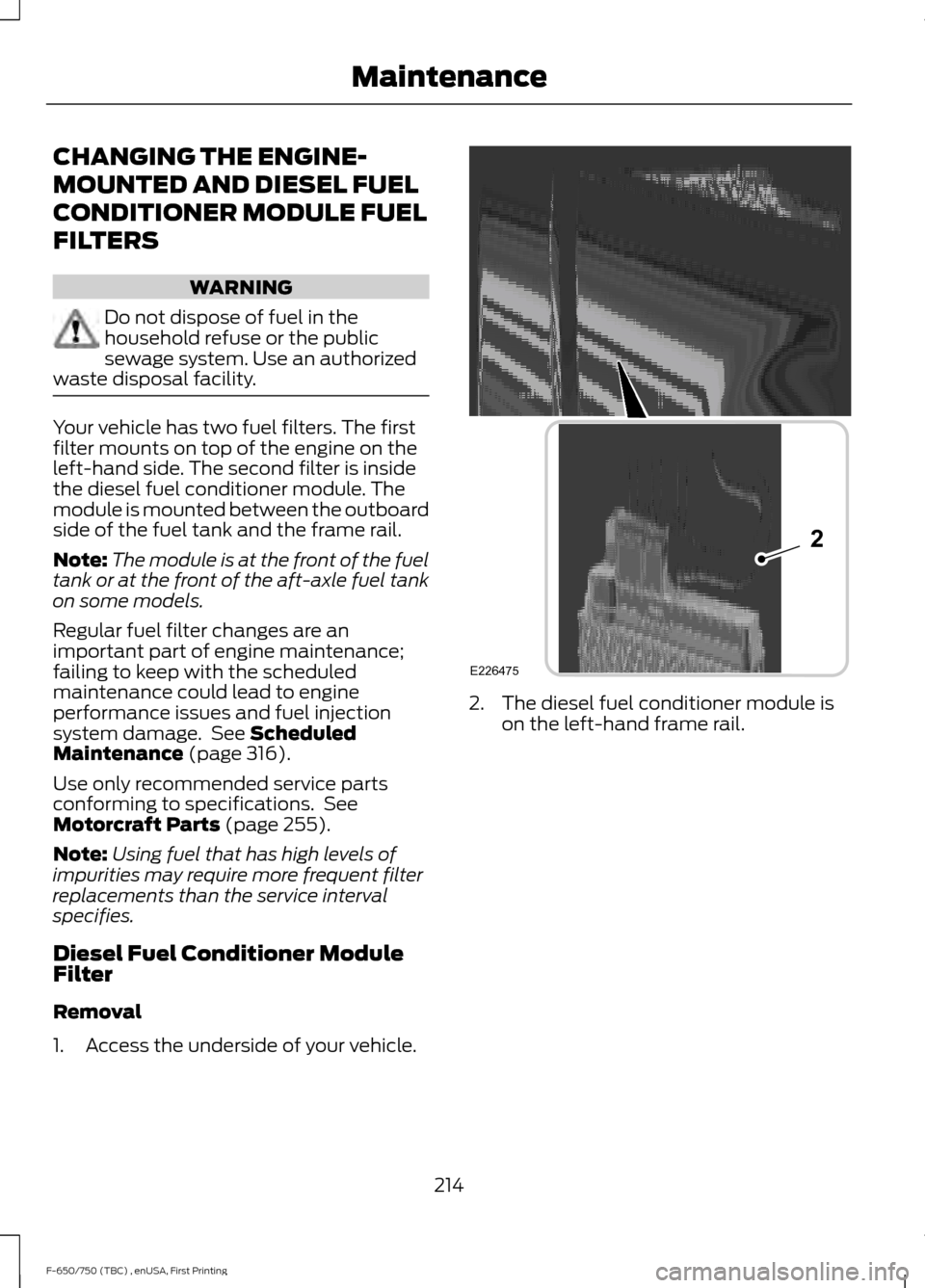
1. Access the underside of your vehicle. 2. The diesel fuel conditioner module is
on the left-hand frame rail.
214
F-650/750 (TBC) , enUSA, First Printing MaintenanceE226475
2
Page 218 of 382
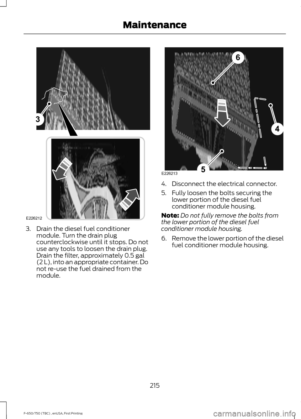
3. Drain the diesel fuel conditioner
module. Turn the drain plug
counterclockwise until it stops. Do not
use any tools to loosen the drain plug.
Drain the filter, approximately 0.5 gal
(2 L), into an appropriate container. Do
not re-use the fuel drained from the
module. 4. Disconnect the electrical connector.
5. Fully loosen the bolts securing the
lower portion of the diesel fuel
conditioner module housing.
Note: Do not fully remove the bolts from
the lower portion of the diesel fuel
conditioner module housing.
6. Remove the lower portion of the diesel
fuel conditioner module housing.
215
F-650/750 (TBC) , enUSA, First Printing Maintenance3
E226212 4
5
6
E226213
Page 219 of 382
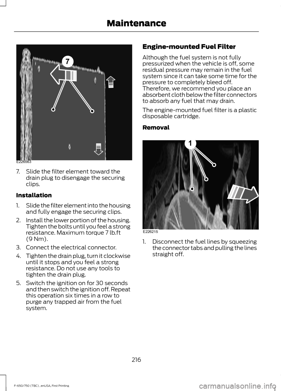
7. Slide the filter element toward the
drain plug to disengage the securing
clips.
Installation
1. Slide the filter element into the housing
and fully engage the securing clips.
2. Install the lower portion of the housing.
Tighten the bolts until you feel a strong
resistance. Maximum torque 7 lb.ft
(9 Nm).
3. Connect the electrical connector.
4. Tighten the drain plug, turn it clockwise
until it stops and you feel a strong
resistance. Do not use any tools to
tighten the drain plug.
5. Switch the ignition on for 30 seconds and then switch the ignition off. Repeat
this operation six times in a row to
purge any trapped air from the fuel
system. Engine-mounted Fuel Filter
Although the fuel system is not fully
pressurized when the vehicle is off, some
residual pressure may remain in the fuel
system since it can take some time for the
pressure to completely bleed off.
Therefore, we recommend you place an
absorbent cloth below the filter connectors
to absorb any fuel that may drain.
The engine-mounted fuel filter is a plastic
disposable cartridge.
Removal
1.
Disconnect the fuel lines by squeezing
the connector tabs and pulling the lines
straight off.
216
F-650/750 (TBC) , enUSA, First Printing Maintenance7
E226563 E226215
1
Page 220 of 382

2.
Rotate the filter fully counterclockwise
until the peg is at the far end of the slot.
3. Pull the filter straight up from the bracket and discard the filter.
Installation
1. Install the new filter into the filter bracket. Turn the filter clockwise to
lock it in place.
2. Reconnect the fuel lines.
3. Switch the ignition on for 30 seconds and then switch the ignition off. Repeat
this operation six times in a row to
purge any trapped air from the fuel
system.
ELECTRICAL SYSTEM
INSPECTION
Periodically inspect electrical connectors
on the outside of the cab and on the engine
and frame for corrosion and tightness.
Exposed terminals, such as the fuel sender,
cranking motor, alternator and
feed-through studs, should be cleaned and re-coated with a lubricant sealing grease
such as Motorcraft Silicone Brake Caliper
Grease and Dielectric Compound XG-3, or
equivalent. This should include the ground
cable connector for batteries, engine and
cab as well as the jump-starting stud.
Accessory Feed Connections
Vehicle electrical systems are complex and
often include powertrain components,
such as engine and transmission controls,
instrument panels and ABS. While most
systems operate on battery voltage (12
volts), some systems can be as high as 90
volts or as low as five volts. See the
Electrical Circuit Diagram Manuals,
available from your vehicle
’s manufacturer,
to make sure that any extra body lights and
accessory connections to circuits are both
appropriate and not overloaded. Do not
make modifications to any vehicle control
system without first contacting an
authorized dealer.
AIR INDUCTION SYSTEM
INSPECTION WARNING
When performing maintenance to
any turbocharged engine with engine
air inlet piping disconnected, keep
loose clothing, jewelry and long hair away
from the engine air inlet piping. A
turbocharger compressor air inlet
protective shield should be installed over
the turbocharger air inlet to reduce the risk
of personal injury or death. Perform a complete inspection of the air
induction system annually.
217
F-650/750 (TBC) , enUSA, First Printing MaintenanceE226214
2
3
Page 221 of 382

In areas where road salt is used,
disassemble the joints of each aluminum
component and inspect for salt build-up
and presence of chlorine that can cause
aluminum particles to flake off and enter
the engine combustion chambers. If
evidence of corrosion is found (usually at
the pipe connections), use a wire brush to
clean the inside of the pipes and inside the
rubber hoses.
If pitting is evident at the joint ends of the
intake pipes, use Motorcraft Silicone
Gasket and Sealant TA-30 to seal the
joints. Make sure no excess material, which
can pull into the engine, is on the inside of
the pipes. If the service condition of the
pipes, hoses or clamps is questionable,
replace the defective part(s).
Make sure to clean all dust and debris out
of the pipes and couplings with a clean,
damp rag before reassembly.
Chassis-mounted Charge Air
Cooler
Visually inspect the core assembly for
debris and clogging of external fins with
the engine off.
Before engine operation, remove any debris
blocking the core.
•
Turbocharger-to-charge air cooler.
• Charge air cooler-to-intake manifold
pipe.
• Mounting bracket.
• Chassis-mounted charge air cooler
core.
Inspect air intake piping:
• Check for accumulation of salt
deposits (where applicable). If present,
disassemble and clean the complete
air intake piping system. If pitting is
evident on the intake piping, use
Motorcraft Silicone Gasket and Sealant
TA-30 to seal joints against leakage.
• Check for loose hoses and clamps. •
Check for ruptured or collapsed hoses.
• Check air cleaner housing for cracks.
EXHAUST SYSTEM
INSPECTION
Note: If your vehicle is equipped with a
catalytic converter or muffler, do not blend
waste oil with diesel fuel. Operate only on
ultra-low sulfur (less than 15 parts per
million sulfur) diesel fuel with a cetane
value of 45 or higher.
If your diesel engine is equipped with a
catalytic converter, it is important to review
the maintenance schedule to make sure
proper functioning of the catalytic
converter. Also, take precautions not to
damage the catalytic converter when
servicing your engine or storing your
vehicle.
218
F-650/750 (TBC) , enUSA, First Printing Maintenance
Page 229 of 382
Specification
Name
Nettoyant pour roues et pneus Motorcraft® (Canada)
ZC-37-A (U.S. & Canada)
CLEANING THE EXTERIOR
Wash your vehicle regularly with cool or
lukewarm water and a neutral pH
shampoo, we recommend Motorcraft
Detail Wash.
• Never use strong household detergents
or soap, for example dish washing or
laundry liquid. These products can
discolor and spot painted surfaces.
• Never wash your vehicle when it is hot
to the touch, or during strong or direct
sunlight.
• Dry your vehicle with a chamois or soft
terry cloth towel to eliminate water
spotting.
• Immediately remove fuel spillages, bird
droppings, insect deposits and road tar.
These may cause damage to your
vehicle ’s paintwork or trim over time.
We recommend Motorcraft Bug and
Tar Remover.
• Remove any exterior accessories, for
example antennas, before entering a
car wash.
Note: Suntan lotions and insect repellents
can damage painted surfaces. If these
substances come in contact with your
vehicle, wash the affected area as soon as
possible. Exterior Chrome Parts
•
Apply a high quality-cleaning product
to bumpers and other chrome parts.
Follow the manufacturer ’s instructions.
We recommend Motorcraft Custom
Bright Metal Cleaner.
• Do not apply the cleaning product to
hot surfaces. Do not leave the cleaning
product on chrome surfaces longer
than the time recommended.
• Using other non-recommended
cleaners can result in severe and
permanent cosmetic damage.
Note: Never use abrasive materials, for
example steel wool or plastic pads as they
can scratch the chrome surface.
Note: Do not use chrome cleaner, metal
cleaner or polish on wheels or wheel covers.
Exterior Plastic Parts
For routine cleaning we recommend
Motorcraft Detail Wash. If tar or grease
spots are present, we recommend
Motorcraft Bug and Tar Remover.
Stripes or Graphics
(If Equipped)
Hand washing your vehicle is preferred
however, pressure washing may be used
under the following conditions:
• Do not use water pressure higher than
2,000 psi (14,000 kPa)
.
• Do not use water hotter than
179°F
(82°C).
• Use a spray with a
40° wide spray
angle pattern.
• Keep the nozzle at a
12 in (305 mm)
distance and 90° angle to your
vehicle's surface.
226
F-650/750 (TBC) , enUSA, First Printing Vehicle Care
Page 233 of 382
CLEANING THE ALLOY
WHEELS (If Equipped)
Note: Do not apply a cleaning chemical to
warm or hot wheel rims and covers.
Note: Some automatic car washes may
cause damage to the finish on your wheel
rims and covers.
Note: Industrial-strength or heavy-duty
cleaners in combination with brush agitation
to remove brake dust and dirt, could wear
away the clear coat finish over a period time.
Note: Do not use hydrofluoric acid-based
or high caustic-based wheel cleaners, steel
wool, fuels or strong household detergents.
Note: If you intend parking your vehicle for
an extended period after cleaning the
wheels with a wheel cleaner, drive your
vehicle for a few minutes before doing so.
This will reduce the risk of increased
corrosion of the brake discs.
Alloy wheels and wheel covers are coated
with a clear coat paint finish. To maintain
their condition we recommend that you:
• Clean the wheels weekly using
Motorcraft Wheel and Tire Cleaner.
Apply using manufacturer's
instructions.
• Use a sponge to remove heavy
deposits of dirt and brake dust
accumulation.
• Rinse thoroughly with a strong stream
of water when you have completed the
cleaning process.
• To remove tar and grease, use
Motorcraft Bug and Tar Remover. VEHICLE STORAGE
If you plan on storing your vehicle for 30
days or more, read the following
maintenance recommendations to make
sure your vehicle stays in good operating
condition.
We engineer and test all motor vehicles
and their components for reliable, regular
driving. Under various conditions,
long-term storage may lead to degraded
engine performance or failure unless you
use specific precautions to preserve engine
components.
General
•
Store all vehicles in a dry, ventilated
place.
• Protect from sunlight, if possible.
• If vehicles are stored outside, they
require regular maintenance to protect
against rust and damage.
Body
• Wash your vehicle thoroughly to
remove dirt, grease, oil, tar or mud from
exterior surfaces, rear-wheel housing
and the underside of front fenders.
• Periodically wash your vehicle if it is
stored in exposed locations.
• Touch-up exposed or primed metal to
prevent rust.
• Cover chrome and stainless steel parts
with a thick coat of auto wax to prevent
discoloration. Re-wax as necessary
when you wash your vehicle.
• Lubricate all hood, door and luggage
compartment hinges and latches with
a light grade oil.
• Cover interior trim to prevent fading.
• Keep all rubber parts free from oil and
solvents.
230
F-650/750 (TBC) , enUSA, First Printing Vehicle Care