2017 FORD EXPEDITION EL tow
[x] Cancel search: towPage 234 of 500
Obtaining a French Owner’sManual
French Owner’s Manual can be obtainedfrom your authorized dealer or bycontacting Helm, Incorporated using thecontact information listed previously in thissection.
REPORTING SAFETY DEFECTS
(U.S. ONLY)
If you believe that your vehicle hasa defect which could cause acrash or could cause injury ordeath, you should immediatelyinform the National HighwayTraffic Safety Administration(NHTSA) in addition to notifyingFord Motor Company.
If NHTSA receives similarcomplaints, it may open aninvestigation, and if it finds that asafety defect exists in a group ofvehicles, it may order a recall andremedy campaign. However,NHTSA cannot become involvedin individual problems betweenyou, your dealer, or Ford MotorCompany.
To contact NHTSA, you may callthe Vehicle Safety Hotlinetoll-free at 1-888-327-4236 (TTY:1-800-424-9153); go towww.safercar.gov; or write to:
Administrator
1200 New Jersey Avenue,Southeast
Washington, D.C. 20590
You can also obtain otherinformation about motor vehiclesafety from www.safercar.gov.
REPORTING SAFETY DEFECTS
(CANADA ONLY)
If you believe that your vehicle has a defectwhich could cause a crash or could causeinjury or death, you should immediatelyinform Transport Canada and Ford ofCanada.
Transport Canada Contact Information
www.tc.gc.ca/eng/motorvehiclesafety/safevehicles-defectinvestigations-index-76.htm (English)Website
www.tc.gc.ca/fra/securiteautomobile/VehiculesSecuritaires-Enquetes-index-76.htm (French)Website
1–800–333–0510Phone
231
Expedition (TB7) Canada/United States of America, enUSA, Edition date: 03/2016, First Printing
Customer AssistanceE142557
Page 237 of 500

Protected componentsFuse amp ratingFuse or relay number
Electronic cooling fan.Relay6
Rear window defroster.Relay7Heated mirror relay.
Electronic cooling fan.Relay8
Run/start relay.Relay9
Power distribution box relay.Relay10
Power running boards.40A*11Heated seats.
Run/start relay.40A*12
Starter relay.30A*13
Electronic cooling fan.50A*14
Not used.—15
Electronic fan.50A*16
Not used.—17
Trailer brake.30A*18
Power point (console).20A*19
4x4 module HAT 2.20A*20
Trailer tow module.30A*21
Passenger power seat.30A*22
Air conditioner clutch relay.Relay23
Trailer tow park lamp relay.Relay24
Not used.—25
ALT sensor.10A**26
4x4 module HAT 1.20A**27
Trailer tow park lamp relay.25A**28
Integrated wheel end solenoid.10A**29
Air conditioner clutch relay.10A**30
Trailer tow back up lamp.15A**31
234
Expedition (TB7) Canada/United States of America, enUSA, Edition date: 03/2016, First Printing
Fuses
Page 238 of 500
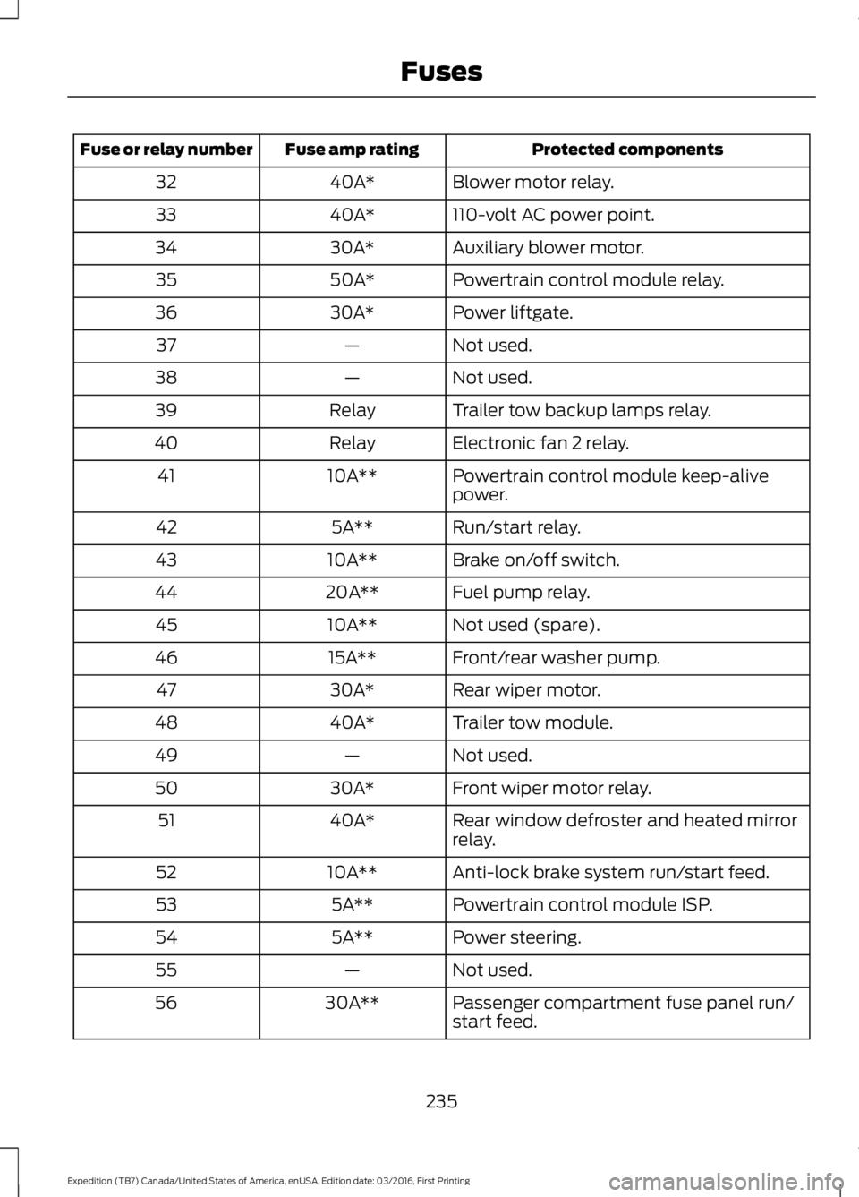
Protected componentsFuse amp ratingFuse or relay number
Blower motor relay.40A*32
110-volt AC power point.40A*33
Auxiliary blower motor.30A*34
Powertrain control module relay.50A*35
Power liftgate.30A*36
Not used.—37
Not used.—38
Trailer tow backup lamps relay.Relay39
Electronic fan 2 relay.Relay40
Powertrain control module keep-alivepower.10A**41
Run/start relay.5A**42
Brake on/off switch.10A**43
Fuel pump relay.20A**44
Not used (spare).10A**45
Front/rear washer pump.15A**46
Rear wiper motor.30A*47
Trailer tow module.40A*48
Not used.—49
Front wiper motor relay.30A*50
Rear window defroster and heated mirrorrelay.40A*51
Anti-lock brake system run/start feed.10A**52
Powertrain control module ISP.5A**53
Power steering.5A**54
Not used.—55
Passenger compartment fuse panel run/start feed.30A**56
235
Expedition (TB7) Canada/United States of America, enUSA, Edition date: 03/2016, First Printing
Fuses
Page 240 of 500

Protected componentsFuse amp ratingFuse or relay number
Not used.—81
Rain sensor.5A**82
Not used.—83
Not used.—84
Wiper motor relay.Relay85
*Cartridge fuses.
**Mini fuses.
Passenger Compartment FusePanel
The fuse panel is located under theright-hand side of the instrument panel.
To remove the trim panel for access to thefuse box, pull the panel toward you andswing it out away from the side andremove it. To reinstall it, line up the tabswith the grooves on the panel, then pushit shut.
237
Expedition (TB7) Canada/United States of America, enUSA, Edition date: 03/2016, First Printing
FusesE205347
Page 252 of 500
Severe Climates
If you drive in extremely cold climates:
•It may be necessary to increase thecoolant concentration above 50%.
•A coolant concentration of 60%provides improved freeze pointprotection. Coolant concentrationsabove 60% decrease the overheatprotection characteristics of thecoolant and may cause enginedamage.
If you drive in extremely hot climates:
•You can decrease the coolantconcentration to 40%.
•Coolant concentrations below 40%decrease the freeze and corrosionprotection characteristics of thecoolant and may cause enginedamage.
Vehicles driven year-round in non-extremeclimates should use prediluted coolant foroptimum cooling system and engineprotection.
Coolant Change
At specific mileage intervals, as listed inthe scheduled maintenance information,the coolant should be changed. Addprediluted coolant approved to the correctspecification. See Capacities andSpecifications (page 304).
Fail-Safe Cooling
Fail-safe cooling allows you to temporarilydrive your vehicle before any incrementalcomponent damage occurs. The fail-safedistance depends on ambienttemperature, vehicle load and terrain.
How Fail-Safe Cooling Works
If the engine begins to overheat, thecoolant temperature gauge moves towardthe red zone:
A warning lamp illuminates anda message may appear in theinformation display.
If the engine reaches a presetover-temperature condition, the engineautomatically switches to alternatingcylinder operation. Each disabled cylinderacts as an air pump and cools the engine.
When this occurs, your vehicle stilloperates, however:
•Engine power is limited.
•The air conditioning system turns off.
Continued operation increases the enginetemperature, causing the engine tocompletely shut down. Your steering andbraking effort increases in this situation.
When the engine temperature cools, youcan re-start the engine. Have your vehiclechecked as soon as possible to minimizeengine damage.
When Fail-Safe Mode Is Activated
WARNINGS
Fail-safe mode is for use duringemergencies only. Operate yourvehicle in fail-safe mode only as longas necessary to bring your vehicle to restin a safe location and seek immediaterepairs. When in fail-safe mode, yourvehicle will have limited power, will not beable to maintain high-speed operation, andmay completely shut down withoutwarning, potentially losing engine power,power steering assist, and power brakeassist, which may increase the possibilityof a crash resulting in serious injury.
Never remove the coolant reservoircap while the engine is running or hot.
249
Expedition (TB7) Canada/United States of America, enUSA, Edition date: 03/2016, First Printing
Maintenance
Page 253 of 500
Your vehicle has limited engine powerwhen in the fail-safe mode, drive yourvehicle with caution. Your vehicle does notmaintain high-speed operation and theengine may operate poorly.
Remember that the engine is capable ofautomatically shutting down to preventengine damage. In this situation:
1. Pull off the road as soon as safelypossible and switch the engine off.
2. If you are a member of a roadsideassistance program, we recommendthat you contact your roadsideassistance service provider.
3. If this is not possible, wait a shortperiod for the engine to cool.
4. Check the coolant level. If the coolantlevel is at or below the minimum mark,add prediluted coolant immediately.
5. When the engine temperature cools,you can re-start the engine. Have yourvehicle checked as soon as possible tominimize engine damage.
Note:Driving your vehicle without repairincreases the chance of engine damage.
Engine Coolant TemperatureManagement (If Equipped)
WARNING
To reduce the risk of crash and injury,be prepared that the vehicle speedmay reduce and the vehicle may notbe able to accelerate with full power untilthe coolant temperature reduces.
If you tow a trailer with your vehicle, theengine may temporarily reach higher atemperature during severe operatingconditions, for example ascending a longor steep grade in high ambienttemperatures.
At this time, you may notice the coolanttemperature gauge moves toward the redzone and a message may appear in theinformation display.
You may notice a reduction in vehiclespeed caused by reduced engine power.In order to manage the engine coolanttemperature. Your vehicle may enter thismode if certain high-temperature andhigh-load conditions take place. Theamount of speed reduction depends onvehicle loading, grade and ambienttemperature. If this occurs, there is no needto pull off the road. You can continue todrive your vehicle.
The air conditioning may automaticallyturn on and off during severe operatingconditions to protect the engine fromoverheating. When the coolanttemperature decreases to the normaloperating temperature, the air conditioningturns on.
If the coolant temperature gauge movesfully into the red zone, or if the coolanttemperature warning or service enginesoon messages appear in your informationdisplay, do the following:
1. Pull off the road as soon as safelypossible and shift the transmission intopark (P).
2. Leave the engine running until thecoolant temperature gauge needlereturns to the normal position. Afterseveral minutes, if the temperaturedoes not drop, follow the remainingsteps.
3.Switch the engine off and wait for it tocool. Check the coolant level.
4. If the coolant level is at or below theminimum mark, add prediluted coolantimmediately.
5. If the coolant level is normal, restartthe engine and continue.
250
Expedition (TB7) Canada/United States of America, enUSA, Edition date: 03/2016, First Printing
Maintenance
Page 259 of 500
3. Press the wiper blade secondarylocking clip.
4. Remove the wiper blade.
Note:Make sure that the wiper arm doesnot spring back against the glass when thewiper blade is not attached.
5. Install in the reverse order.
Note:Make sure that the wiper blade locksinto place.
ADJUSTING THE HEADLAMPS
Vertical Aim Adjustment
The headlamps on your vehicle areproperly aimed at the assembly plant. Ifyour vehicle has been in an accident,contact an authorized dealer to check andrealign your headlamps.
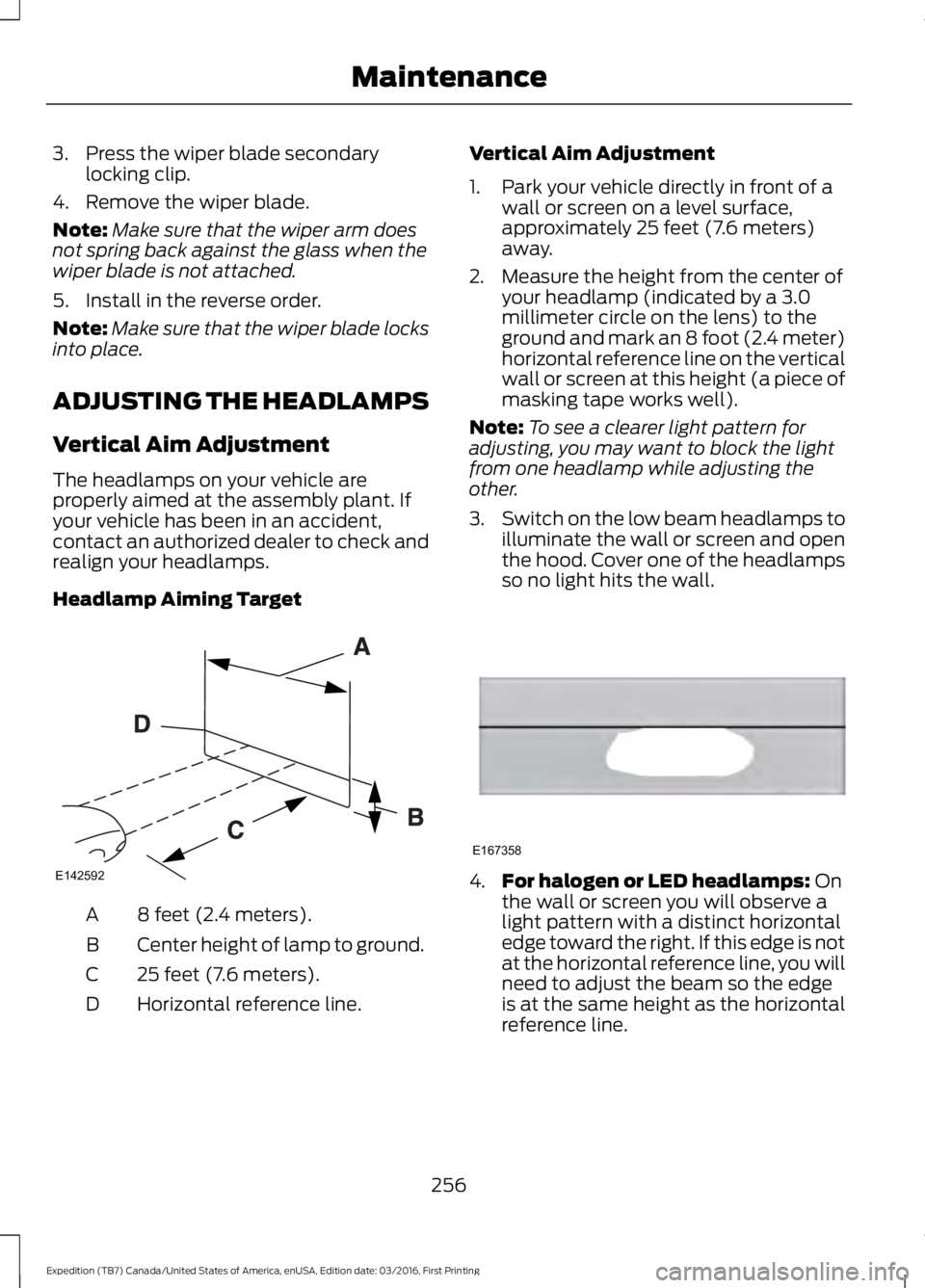
Headlamp Aiming Target
8 feet (2.4 meters).A
Center height of lamp to ground.B
25 feet (7.6 meters).C
Horizontal reference line.D
Vertical Aim Adjustment
1. Park your vehicle directly in front of awall or screen on a level surface,approximately 25 feet (7.6 meters)away.
2. Measure the height from the center ofyour headlamp (indicated by a 3.0millimeter circle on the lens) to theground and mark an 8 foot (2.4 meter)horizontal reference line on the verticalwall or screen at this height (a piece ofmasking tape works well).
Note:To see a clearer light pattern foradjusting, you may want to block the lightfrom one headlamp while adjusting theother.
3.Switch on the low beam headlamps toilluminate the wall or screen and openthe hood. Cover one of the headlampsso no light hits the wall.
4.For halogen or LED headlamps: Onthe wall or screen you will observe alight pattern with a distinct horizontaledge toward the right. If this edge is notat the horizontal reference line, you willneed to adjust the beam so the edgeis at the same height as the horizontalreference line.
256
Expedition (TB7) Canada/United States of America, enUSA, Edition date: 03/2016, First Printing
MaintenanceE142592 E167358
Page 266 of 500

5. Release the three clamps that securethe cover to the air filter housing. Pushthe air filter cover toward the center ofthe vehicle and up slightly to release it.
6.Remove the air filter element from theair filter housing.
7. Install the new air filter element.
8.Replace the air filter housing cover andsecure all the clamps. Be careful notto crimp the filter element edgesbetween the air filter housing and coverand ensure that you properly align thetabs on the edge into the slots.
9. Slip the air tube onto the air filterhousing and tighten the air-tube clampbolt snugly. Do not over tightenair-tube clamp bolt.
10. Reconnect the mass air flow sensorelectrical connector to the outlettube. Make sure the locking tab onthe connector is in the locked position(connector shown from below forclarity).
263
Expedition (TB7) Canada/United States of America, enUSA, Edition date: 03/2016, First Printing
MaintenanceE163758 E163759 E163760