2017 FORD EXPEDITION EL brake light
[x] Cancel search: brake lightPage 211 of 500
Integrated Hitch Rating
WARNING
Towing trailers beyond the maximumtongue weight exceeds the limit ofthe towing system and could resultin vehicle structural damage, loss of vehiclecontrol and personal injury.
The standard integrated hitch has tworatings depending on mode of operation:
•Weight-carrying mode requires a drawbar and hitch ball. The draw barsupports all the vertical tongue load ofthe trailer.
•Weight-distributing mode requires anaftermarket weight-distributingsystem, which includes draw bar, hitchball, spring bars and snap-up brackets.This system distributes the verticaltongue load of the trailer between thetruck and the trailer.
Maximum Tongue WeightMaximum Trailer WeightMode
600 lb (272 kg)6000 lb (2721 kg)Weight carrying
920 lb (417 kg)9200 lb (4173 kg)Weight distributing
Note:These are hitch ratings only. Actualvehicle ratings are dependent on engine,transmission and axle combinations.
Weight-distributing Hitch - Vehicleswithout Automatic LevelingSuspension
WARNING
Do not adjust a weight-distributinghitch to any position where the rearbumper of the vehicle is higher thanit was before attaching the trailer. Doingso will defeat the function of theweight-distributing hitch, which may causeunpredictable handling, and could resultin serious personal injury.
When hooking-up a trailer using aweight-distributing hitch, always use thefollowing procedure:
1. Park the loaded vehicle, without thetrailer, on a level surface.
2. Measure the height to the top of yourvehicle's front wheel opening on thefender. This is H1.
3.Attach the loaded trailer to your vehiclewithout the weight-distributing barsconnected.
4. Measure the height to the top of yourvehicle's front wheel opening on thefender a second time. This is H2.
5. Install and adjust the tension in theweight-distributing bars so that theheight of your vehicle's front wheelopening on the fender is approximatelyhalf the way down from H2, toward H1.
6.Check that the trailer is level or slightlynose down toward your vehicle. If not,adjust the ball height accordingly andrepeat Steps 2-6.
When the trailer is level or slightly nosedown toward the vehicle:
•Lock the bar tension adjuster in place.
•Check that the trailer tongue securelyattaches and locks onto the hitch.
•Install safety chains, lighting, and trailerbrake controls as required by law or thetrailer manufacturer.
208
Expedition (TB7) Canada/United States of America, enUSA, Edition date: 03/2016, First Printing
Towing
Page 212 of 500
Weight-distributing Hitch - Vehicleswith Automatic Leveling Suspension
WARNING
Do not adjust a weight-distributinghitch to any position where the rearbumper of the vehicle is higher thanit was before attaching the trailer. Doingso will defeat the function of theweight-distributing hitch, which may causeunpredictable handling, and could resultin serious personal injury.
Note:If you do not move the loaded vehiclefor approximately 12 hours, the levelingsystem may bleed down to a lower height.This can be especially apparent if you leavea trailer attached to the parked vehicle forlong periods. You must drive your vehicle inorder to re-level the suspension.
When hooking-up a trailer using aweight-distributing hitch, always use thefollowing procedure:
1. Load the interior of the vehicle to aweight similar to that which you intendto carry when towing. This includesthings such as passenger weight andcargo.
2. Drive the vehicle for approximately 2miles (3 kilometers) to re-level thesuspension.
3. Park the loaded vehicle, without thetrailer, on a level surface.
4. Measure the height to the top of yourvehicle's front wheel opening on thefender. This is H1.
5.Attach the loaded trailer to your vehiclewithout the weight-distributing barsconnected.
6.Make sure you securely attach and lockthe trailer tongue to the hitch.
7.Install safety chains, lighting, and trailerbrake controls as required by law or thetrailer manufacturer.
8. Drive the vehicle and trailer at 20–25mph (32–40 km/h) for approximately2 miles (3 kilometers) to re-level thesuspension.
9. Park your vehicle and trailer on a levelsurface.
10.Measure the height to the top of yourvehicle's front wheel opening on thefender a second time. This is H2.
11. Install and adjust the tension in theweight-distributing bars so that theheight of your vehicle's front wheelopening on the fender isapproximately half the way downfrom H2, toward H1.
12. Check that the trailer is level orslightly nose down toward yourvehicle. If not, remove the trailer,adjust the ball height accordingly andrepeat Steps 5-11.
When the trailer is level or slightly nosedown toward the vehicle:
•Lock the bar tension adjuster in place.
•Check that the trailer tongue securelyattaches and locks onto the hitch.
•Install safety chains, lighting, and trailerbrake controls as required by law or thetrailer manufacturer.
Safety Chains
Note:Do not attach safety chains to thebumper.
Always connect the safety chains to theframe or hook retainers of your vehiclehitch.
To connect the safety chains, cross thechains under the trailer tongue and allowenough slack for turning tight corners. Donot allow the chains to drag on the ground.
209
Expedition (TB7) Canada/United States of America, enUSA, Edition date: 03/2016, First Printing
Towing
Page 216 of 500
•Your vehicle's brake system and thetrailer brake system workindependently of each other. Changingthe gain setting on the controller doesnot affect the operation of yourvehicle's brakes whether you attach atrailer or not.
•When you switch the engine off, thecontroller output is disabled and thedisplay and module shut down. Thecontroller module and display turn onwhen you switch the ignition on.
•The trailer brake controller is only afactory-installed or dealer-installeditem. Ford is not responsible forwarranty or performance of thecontroller due to misuse or customerinstallation.
Trailer Lamps
WARNING
Never connect any trailer lamp wiringto the vehicle's tail lamp wiring; thismay damage the electrical systemresulting in fire. Contact your authorizeddealer as soon as possible for assistancein proper trailer tow wiring installation.Additional electrical equipment may berequired.
Trailer lamps are required on most towedvehicles. Make sure all running lights, brakelights, turn signals and hazard lights areworking.
Before Towing a Trailer
Practice turning, stopping and backing upto get the feel of your vehicle-trailercombination before starting on a trip.When turning, make wider turns so thetrailer wheels clear curbs and otherobstacles.
When Towing a Trailer
•Do not drive faster than 70 mph (113km/h) during the first 500 miles (800kilometers).
•Do not make full-throttle starts.
•Check your hitch, electrical connectionsand trailer wheel lug nuts thoroughlyafter you have traveled 50 miles (80kilometers).
•When stopped in congested or heavytraffic during hot weather, place thegearshift in position P to aid engine andtransmission cooling and to help A/Cperformance.
•Turn off the speed control with heavyloads or in hilly terrain. The speedcontrol may turn off automaticallywhen you are towing on long, steepgrades.
•Shift to a lower gear when driving downa long or steep hill. Do not apply thebrakes continuously, as they mayoverheat and become less effective.
•If your transmission is equipped with aGrade Assist or Tow/Haul feature, usethis feature when towing. This providesengine braking and helps eliminateexcessive transmission shifting foroptimum fuel economy andtransmission cooling.
•If your vehicle is equipped withAdvanceTrac with RSC, this systemmay turn on during typical corneringmaneuvers with a heavily loaded trailer.This is normal. Turning the corner at aslower speed while towing may reducethis tendency.
•If you are towing a trailer frequently inhot weather, hilly conditions, at thegross combined weight rating (or anycombination of these factors), considerrefilling your rear axle with syntheticgear lubricant (if the axle is not alreadyfilled with it). See Capacities andSpecifications (page 304).
213
Expedition (TB7) Canada/United States of America, enUSA, Edition date: 03/2016, First Printing
Towing
Page 220 of 500
Exiting Four-wheel-down Towing
To exit four-wheel-down towing and returnthe transfer case to its 2H position:
1.With your vehicle still properly securedto the tow vehicle, put the ignition inthe on position, but do not start theengine. If your vehicle has an ignitionkey, turn the key to on. If your vehiclehas intelligent access, press the engineSTART/STOP button twice withoutpressing the brake pedal.
2. Press and hold the brake pedal.
3.Shift the transmission out of N and intoany gear.
4. Release the brake pedal.
Note:If completed successfully, theinstrument cluster displays 4X2, andNEUTRAL TOW DISABLED.
Note:If the indicator light and message donot display, you must perform the procedureagain from the beginning.
Note:You may hear an audible noise as thetransfer case shifts out of its neutralposition. This is normal.
Note:If SHIFT DELAY PULL FORWARDdisplays in the instrument cluster, transfercase gear tooth blockage is present. See theinstructions after this section.
5. Apply the parking brake, and thendisconnect the vehicle from the towvehicle.
6. Release the parking brake, start theengine, and shift the transmission toposition D to make sure the transfercase is out of position N.
7. If the transfer case does notsuccessfully shift out of position N, setthe parking brake until you can haveyour vehicle serviced.
Resolving the SHIFT DELAY PULLFORWARD Message
If the instrument cluster displays SHIFTDELAY PULL FORWARD perform thefollowing:
1. Press and hold the brake pedal.
2. Put the transmission into position N,and then start the engine.
3. With the engine running, shift thetransmission to position D and let thevehicle roll forward, up to 3 feet (1meter). You may hear an audible noiseas the transfer case shifts out of itsneutral position. This is normal.
4. Make sure the instrument clusterdisplays NEUTRAL TOW DISABLED.
217
Expedition (TB7) Canada/United States of America, enUSA, Edition date: 03/2016, First Printing
Towing
Page 222 of 500

•Avoid using speed control in hillyterrain.
•Do not rest your foot on the brakepedal while driving.
•Avoid carrying unnecessary weight.
•Avoid adding particular accessories toyour vehicle (e.g. bug deflectors,rollbars/light bars, running boards, skiracks).
•Avoid driving with the wheels out ofalignment.
DRIVING THROUGH WATER
WARNING
Do not drive through flowing or deepwater as you may lose control of yourvehicle.
Note:Driving through standing water cancause vehicle damage.
Note:Engine damage can occur if waterenters the air filter.
Before driving through standing water,check the depth. Never drive through waterthat is higher than the bottom of the wheelhubs.
When driving through standing water, drivevery slowly and do not stop your vehicle.Your brake performance and traction maybe limited. After driving through water andas soon as it is safe to do so:
•Lightly press the brake pedal to dry thebrakes and to check that they work.
•Check that the horn works.
•Check that the exterior lights work.
•Turn the steering wheel to check thatthe steering power assist works.
FLOOR MATS (If Equipped)
WARNINGS
Always use floor mats that aredesigned to fit the foot well of yourvehicle. Only use floor mats thatleave the pedal area unobstructed. Onlyuse floor mats that are firmly secured toretention posts so that they cannot slip outof position and interfere with the pedalsor impair safe operation of your vehicle inother ways.
Pedals that cannot move freely cancause loss of vehicle control andincrease the risk of serious personalinjury.
Always make sure that the floormats are properly attached to theretention posts in the carpet that aresupplied with your vehicle. Floor mats mustbe properly secured to both retention poststo make sure mats do not shift out ofposition.
Never place floor mats or any othercovering in the vehicle foot well thatcannot be properly secured toprevent them from moving and interferingwith the pedals or the ability to control thevehicle.
219
Expedition (TB7) Canada/United States of America, enUSA, Edition date: 03/2016, First Printing
Driving HintsE176913
Page 239 of 500
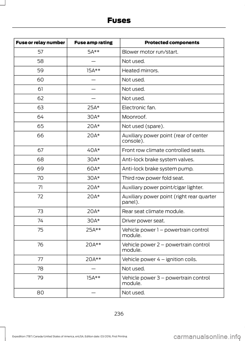
Protected componentsFuse amp ratingFuse or relay number
Blower motor run/start.5A**57
Not used.—58
Heated mirrors.15A**59
Not used.—60
Not used.—61
Not used.—62
Electronic fan.25A*63
Moonroof.30A*64
Not used (spare).20A*65
Auxiliary power point (rear of centerconsole).20A*66
Front row climate controlled seats.40A*67
Anti-lock brake system valves.30A*68
Anti-lock brake system pump.60A*69
Third row power fold seat.30A*70
Auxiliary power point/cigar lighter.20A*71
Auxiliary power point (right rear quarterpanel).20A*72
Rear seat climate module.20A*73
Driver power seat.30A*74
Vehicle power 1 – powertrain controlmodule.25A**75
Vehicle power 2 – powertrain controlmodule.20A**76
Vehicle power 4 – ignition coils.20A**77
Not used.—78
Vehicle power 3 – powertrain controlmodule.15A**79
Not used.—80
236
Expedition (TB7) Canada/United States of America, enUSA, Edition date: 03/2016, First Printing
Fuses
Page 242 of 500
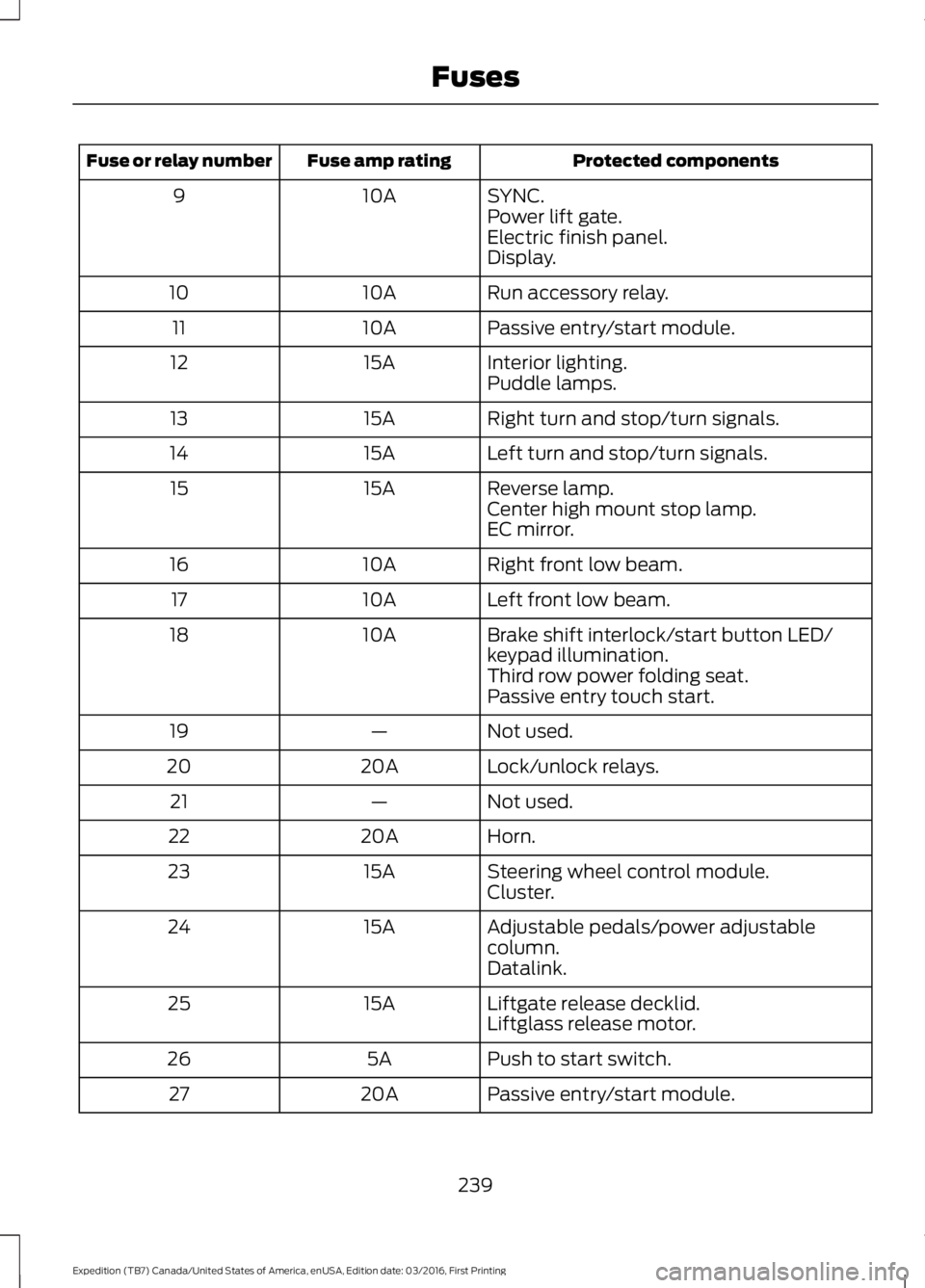
Protected componentsFuse amp ratingFuse or relay number
SYNC.10A9Power lift gate.Electric finish panel.Display.
Run accessory relay.10A10
Passive entry/start module.10A11
Interior lighting.15A12Puddle lamps.
Right turn and stop/turn signals.15A13
Left turn and stop/turn signals.15A14
Reverse lamp.15A15Center high mount stop lamp.EC mirror.
Right front low beam.10A16
Left front low beam.10A17
Brake shift interlock/start button LED/keypad illumination.10A18
Third row power folding seat.Passive entry touch start.
Not used.—19
Lock/unlock relays.20A20
Not used.—21
Horn.20A22
Steering wheel control module.15A23Cluster.
Adjustable pedals/power adjustablecolumn.15A24
Datalink.
Liftgate release decklid.15A25Liftglass release motor.
Push to start switch.5A26
Passive entry/start module.20A27
239
Expedition (TB7) Canada/United States of America, enUSA, Edition date: 03/2016, First Printing
Fuses
Page 263 of 500

LED Rear Lamp, Brake Lamp, RearDirection Indicator and ReverseLamp Bulbs (If Equipped)
These lamps have LED bulbs. Contact anauthorized dealer.
Central High-mounted Brake LampBulb
1.Switch all of the lamps and the ignitionoff.
2. Remove the retaining bolts from thelamp assembly.
3. Remove the lamp and unclip the bulbholder.
4. Remove the bulb by pulling it straightout.
LED Central High-mounted BrakeLamp Bulb (If Equipped)
These lamps have LED bulbs. Contact anauthorized dealer.
License Plate Lamp Bulb
1. Use a suitable tool, for example ascrewdriver, to carefully remove thelamp.
2.Turn the bulb holder counterclockwiseand remove it.
3. Remove the bulb by pulling it straightout.
Side Direction Indicator Bulb
These lamps have LED bulbs. Contact anauthorized dealer.
BULB SPECIFICATION CHART
Replacement bulbs are specified in thechart below. Headlamp bulbs must bemarked with an authorized D.O.T. markingfor North America to make sure they havethe proper lamp performance, lightbrightness, light pattern and safe visibility.The correct bulbs will not damage thelamp assembly or void the lamp assemblywarranty and will provide quality bulbillumination time.
260
Expedition (TB7) Canada/United States of America, enUSA, Edition date: 03/2016, First Printing
MaintenanceE205572 E205573 E205571