2017 FORD EXPEDITION EL brake
[x] Cancel search: brakePage 275 of 500
•Check tire pressures and set tireinflation per the Tire Label.
•Check brake pedal operation. Driveyour vehicle 15 ft (4.5 m) back andforth to remove rust build-up.
•Check fluid levels (including coolant,oil and gas) to make sure there are noleaks, and fluids are at recommendedlevels.
•If you remove the battery, clean thebattery cable ends and check fordamage.
Contact an authorized dealer if you haveany concerns or issues.
272
Expedition (TB7) Canada/United States of America, enUSA, Edition date: 03/2016, First Printing
Vehicle Care
Page 287 of 500
Tire Label (affixed to either thedoor hinge pillar, door-latch post,or the door edge that meets thedoor-latch post, next to thedriver's seating position), or TireLabel located on the B-pillar orthe edge of the driver's door.Failure to follow the tire pressurerecommendations can causeuneven treadwear patterns andadversely affect the way yourvehicle handles.
Note:Do not reduce tire pressureto change the ride characteristicsof the vehicle. If you do notmaintain the inflation pressure atthe levels specified by Ford, yourvehicle may experience a conditionknown as shimmy. Shimmy is asevere vibration and oscillation inthe steering wheel after the vehicletravels over a bump or dip in theroad that does not dampen out byitself. Shimmy may result fromsignificant under-inflation of thetires, improper tires (load range,size, or type), or vehiclemodifications such as lift-kits. Inthe event that your vehicleexperiences shimmy, you shouldslowly reduce speed by either liftingoff the accelerator pedal or lightlyapplying the brakes. The shimmywill cease as the vehicle speeddecreases.
Maximum Inflation Pressure isthe tire manufacturer's maximumpermissible pressure and thepressure at which the maximum
load can be carried by the tire. Thispressure is normally higher than
the manufacturer’s recommendedcold inflation pressure which canbe found on the SafetyCompliance Certification Label(affixed to either the door hingepillar, door-latch post, or the dooredge that meets the door-latchpost, next to the driver's seatingposition), or Tire Label located onthe B-pillar or the edge of thedriver's door. The cold inflationpressure should never be set lowerthan the recommended pressureon the Safety ComplianceCertification Label or Tire Label.
When weather temperaturechanges occur, tire inflationpressures also change. A 10°F(6°C) temperature drop cancause a corresponding drop of 1psi (7 kPa) in inflation pressure.Check your tire pressuresfrequently and adjust them to theproper pressure which can befound on the Safety ComplianceCertification Label or Tire Label.
To check the pressure in yourtire(s):
1. Make sure the tires are cool,meaning they are not hot fromdriving even a mile.
284
Expedition (TB7) Canada/United States of America, enUSA, Edition date: 03/2016, First Printing
Wheels and Tires
Page 294 of 500

USING SNOW CHAINS
WARNING
Snow tires must be the same size,load index and speed rating as thoseoriginally provided by Ford. Use ofany tire or wheel not recommended byFord can affect the safety andperformance of your vehicle, which couldresult in an increased risk of loss of control,vehicle rollover, personal injury and death.Additionally, the use of non-recommendedtires and wheels can cause steering,suspension, axle, transfer case or powertransfer unit failure. Follow the Fordrecommended tire inflation pressure foundon the Safety Compliance CertificationLabel (on the door hinge pillar, door latchpost or the door edge that meets the doorlatch post, next to the driver seat), or TireLabel on the B-Pillar or the edge of thedriver door. Failure to follow the tirepressure recommendations can causeuneven treadwear patterns and adverselyaffect the way your vehicle handles.
Note:The suspension insulation andbumpers will help prevent vehicle damage.Do not remove these components from yourvehicle when using snow tires and chains.
The tires on your vehicle have all-weathertreads to provide traction in rain and snow.However, in some climates, you may needto use snow tires and cables. If you needto use cables, it is recommended that steelwheels (of the same size andspecifications) be used, as cables may chipaluminum wheels.
Follow these guidelines when using snowtires and chains:
•If possible, avoid fully loading yourvehicle.
•Use only cable type chains or chainsoffered by Ford/Lincoln as anaccessory or equivalent. Otherconventional link type chains maycontact and cause damage to thevehicle's wheel house and/or body.
•Do not install chains on the front tiresas this may interfere with suspensioncomponents.
•Only certain snow cables or chainshave been approved by Ford/Lincolnas safe for use on your vehicle with thefollowing tires: 265/70R17 and275/65R18.
•You should install snow cables orchains that have been rated as SAEClass S.
•Install chains securely, verifying thatthe chains do not touch any wiring,brake lines, or fuel lines.
•Do not exceed 31 mph (50 km/h) orless if recommended by the chainmanufacturer while using snow chains.
•Drive cautiously. If you hear the chainsrub or bang against your vehicle, stopand retighten the chains. If this doesnot work, remove the chains to preventdamage to your vehicle.
•Remove the tire chains when they areno longer needed. Do not use tirechains on dry roads.
•Purchase chains or cables from amanufacturer that clearly labels bodyto tire dimension restrictions. The snowchains or cables must be mounted inpairs on the rear tires only.
If you have any questions regarding snowchains or cables, please contact yourauthorized dealer.
291
Expedition (TB7) Canada/United States of America, enUSA, Edition date: 03/2016, First Printing
Wheels and Tires
Page 300 of 500

11.Set all four tires to the recommendedair pressure as indicated on theSafety Compliance CertificationLabel (affixed to either the door hingepillar, door-latch post, or the dooredge that meets the door-latch post,next to the driver's seating position)or Tire Label located on the B-Pillaror the edge of the driver's door.
CHANGING A ROAD WHEEL
WARNINGS
The use of tire sealant may damageyour tire pressure monitoring systemand should only be used in roadsideemergencies. If you must use a sealant, theFord Tire Mobility Kit sealant should beused. The tire pressure monitoring systemsensor and valve stem on the wheel mustbe replaced by an authorized dealer afteruse of the sealant.
If the tire pressure monitor sensorbecomes damaged, it will no longerfunction. See Tire PressureMonitoring System (page 292).
Note:The tire pressure monitoring systemindicator light will illuminate when the sparetire is in use. To restore the full function ofthe monitoring system, all road wheelsequipped with tire pressure monitoringsensors must be mounted on this vehicle.
If you get a flat tire while driving, do notapply the brake heavily. Instead, graduallydecrease your speed. Hold the steeringwheel firmly and slowly move to a safeplace on the side of the road.
Have a flat serviced by an authorizeddealer in order to prevent damage to thesystem sensors See Tire PressureMonitoring System (page 292). Replacethe spare tire with a road tire as soon aspossible. During repairing or replacing ofthe flat tire, have the authorized dealerinspect the system sensor for damage.
Dissimilar Spare Wheel and TireAssembly Information
WARNING
Failure to follow these guidelinescould result in an increased risk ofloss of vehicle control, injury or death.
If you have a dissimilar spare wheel andtire, then it is intended for temporary useonly. This means that if you need to use it,you should replace it as soon as possiblewith a road wheel and tire assembly thatis the same size and type as the road tiresand wheels that were originally providedby Ford. If the dissimilar spare tire or wheelis damaged, it should be replaced ratherthan repaired.
A dissimilar spare wheel and tire assemblyis defined as a spare wheel and tireassembly that is different in brand, size orappearance from the road tires and wheelsand can be one of three types:
1.T-type mini-spare: This spare tirebegins with the letter T for tire size andmay have Temporary Use Only molded inthe sidewall.
2.Full-size dissimilar spare with labelon wheel: This spare tire has a label onthe wheel that states: THIS WHEEL ANDTIRE ASSEMBLY FOR TEMPORARY USEONLY
297
Expedition (TB7) Canada/United States of America, enUSA, Edition date: 03/2016, First Printing
Wheels and Tires
Page 302 of 500

Tire Change Procedure
WARNINGS
Only use replacement tires andwheels that are the same size, loadindex, speed rating and type (suchas P-metric versus LT-metric or all-seasonversus all-terrain) as those originallyprovided by Ford. The recommended tireand wheel size may be found on either theSafety Compliance Certification Label(affixed to either the door hinge pillar,door-latch post, or the door edge thatmeets the door-latch post, next to thedriver’s seating position) or the Tire Labelwhich is located on the B-Pillar or edge ofthe driver’s door. If this information is notfound on these labels then you shouldcontact your authorized dealer as soon aspossible. Use of any tire or wheel notrecommended by Ford can affect thesafety and performance of your vehicle,which could result in an increased risk ofloss of vehicle control, vehicle rollover,personal injury and death. Additionally theuse of non-recommended tires and wheelscould cause steering, suspension, axle,transfer case or power transfer unit failure.If you have questions regarding tirereplacement, contact your authorizeddealer as soon as possible.
When one of the front wheels is offthe ground, the transmission alonewill not prevent the vehicle frommoving or slipping off the jack.
To help prevent the vehicle frommoving when you change a tire, besure to place the transmission in park(P), set the parking brake and block (inboth directions) the wheel that isdiagonally opposite (other side and end ofthe vehicle) to the tire being changed.
Never get underneath a vehicle thatis supported only by a jack. If thevehicle slips off the jack, you orsomeone else could be seriously injured.
WARNINGS
Do not attempt to change a tire onthe side of the vehicle close tomoving traffic. Pull far enough off theroad to avoid the danger of being hit whenoperating the jack or changing the wheel.
Always use the jack provided asoriginal equipment with your vehicle.If using a jack other than the oneprovided as original equipment with yourvehicle, make sure the jack capacity isadequate for the vehicle weight, includingany vehicle cargo or modifications.
Disable the power running boardsbefore jacking, lifting, or placing anyobject under the vehicle. Never placeyour hand between the power runningboard and the vehicle as extended powerrunning boards will retract when the doorsare closed. Failure to follow theseinstructions may result in personal injury.
Failure to follow these instructionswhen using the spare tire carriercould cause loss of the wheel andtire and lead to personal injury: Only usethe spare tire carrier to stow the tire andwheel combination specified on the TireLabel or Safety Compliance CertificationLabel on the B-Pillar or the edge of thedriver door. Other tire and wheelcombinations could cause the carrier tofail if it does not fit securely or is too heavy.Do not use impact tools or power toolsoperating over 200 RPM, which may causewinch malfunction and prevent a securefit. Override the winch at least three times(there will be an audible click each time)to ensure a tight secure fit of the wheel andtire.
Note:Passengers should not remain in thevehicle when the vehicle is being jacked.
299
Expedition (TB7) Canada/United States of America, enUSA, Edition date: 03/2016, First Printing
Wheels and Tires
Page 303 of 500
Park on a level surface, activate the hazardflashers and set the parking brake. Then,place the transmission in park (P) and turnthe engine off.
Removing the Jack and Tools
Note:Pay close attention to the orientationof the bag, because it will have to bereinstalled after changing the tire.
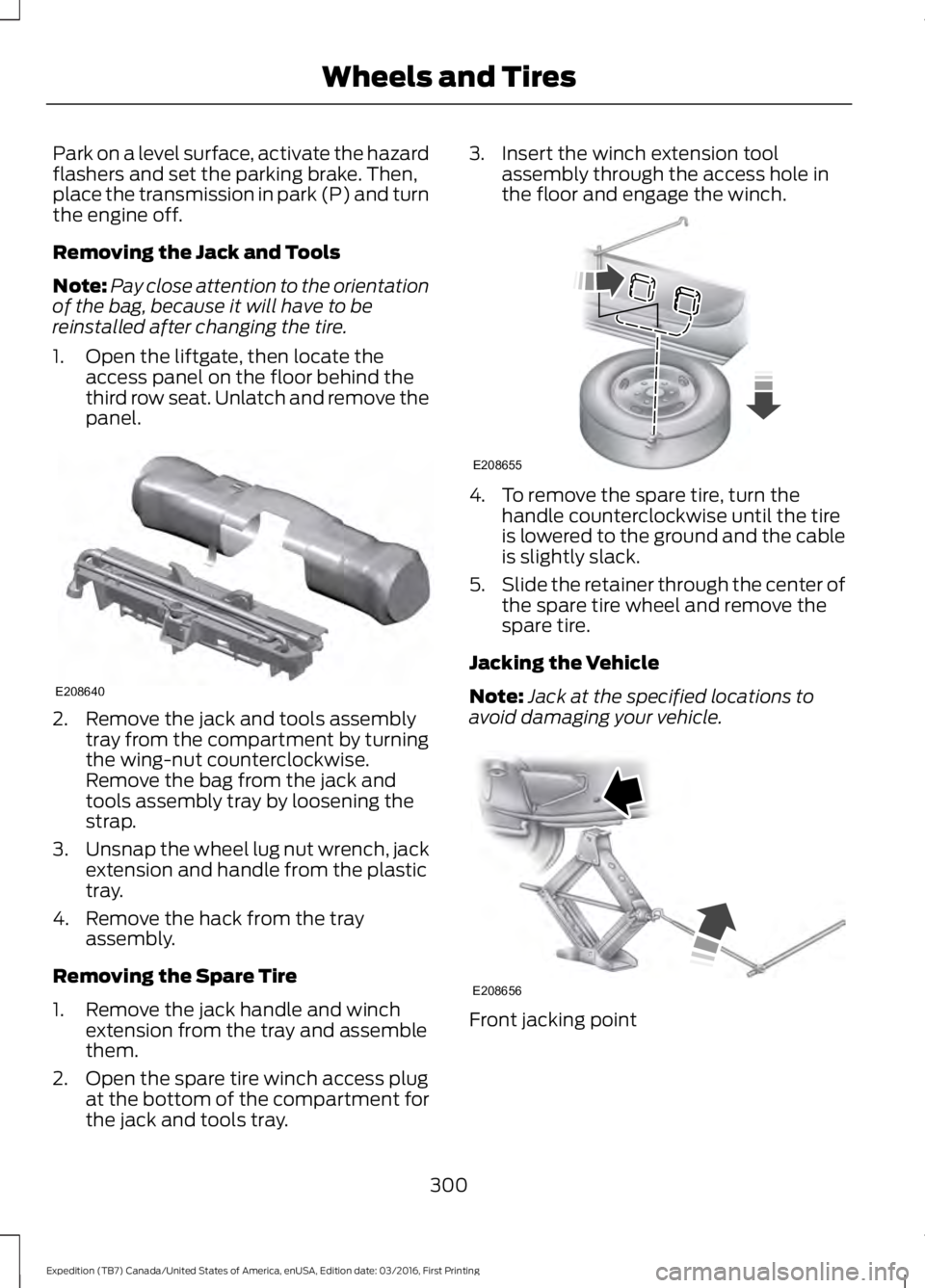
1. Open the liftgate, then locate theaccess panel on the floor behind thethird row seat. Unlatch and remove thepanel.
2. Remove the jack and tools assemblytray from the compartment by turningthe wing-nut counterclockwise.Remove the bag from the jack andtools assembly tray by loosening thestrap.
3.Unsnap the wheel lug nut wrench, jackextension and handle from the plastictray.
4. Remove the hack from the trayassembly.
Removing the Spare Tire
1. Remove the jack handle and winchextension from the tray and assemblethem.
2. Open the spare tire winch access plugat the bottom of the compartment forthe jack and tools tray.
3. Insert the winch extension toolassembly through the access hole inthe floor and engage the winch.
4. To remove the spare tire, turn thehandle counterclockwise until the tireis lowered to the ground and the cableis slightly slack.
5.Slide the retainer through the center ofthe spare tire wheel and remove thespare tire.
Jacking the Vehicle
Note:Jack at the specified locations toavoid damaging your vehicle.
Front jacking point
300
Expedition (TB7) Canada/United States of America, enUSA, Edition date: 03/2016, First Printing
Wheels and TiresE208640 E208655 E208656
Page 305 of 500
5. Remove the jack and fully tighten thelug nuts in the order shown. SeeTechnical Specifications (page 302).
Stowing the Flat or Spare Tire
1.Lay the tire on the ground, near the rearof the vehicle, with the valve stem sidefacing up.
2. Slide the wheel partially under thevehicle and install the retainer throughthe wheel center. If equipped, you mayhave to remove the wheel center capprior to pushing the retainer throughthe center of the wheel. To remove thecenter cap, press it off with the jacktool from the inner side of the wheel.Pull on the cable to align thecomponents at the end of the cable.
3. Assemble the jack handle and winchextension, then insert the winchextension through the access holebehind the third row seat and engagethe winch.
4. Turn the jack handle clockwise untilthe tire is raised to its stowed positionunderneath the vehicle. The wrenchwill become harder to turn and thespare tire winch will rachet or slip whenthe tire is raised to maximum tightness.A clicking sound will be heard from thewinch indicating that the tire is properlystowed.
5. Disassembly the jack tool and winchextension and snap them back into thetool tray.
6. Reinstall the jack bag properly aroundthe jack and tool assembly tray, makingsure the strap is fastened.
7. Close the access hole with the rubberplug.
8. Reinstall the tray into the vehicle andsecure it with the wing nut.
TECHNICAL SPECIFICATIONS
Wheel Lug Nut Torque Specifications
WARNING
When you install a wheel, always remove any corrosion, dirt or foreign materialspresent on the mounting surfaces of the wheel or the surface of the wheel hub,brake drum or brake disc that contacts the wheel. Make sure to secure any fastenersthat attach the rotor to the hub so they do not interfere with the mounting surfaces ofthe wheel. Installing wheels without correct metal-to-metal contact at the wheel mountingsurfaces can cause the wheel nuts to loosen and the wheel to come off while your vehicleis in motion, resulting in loss of vehicle control, personal injury or death.
lb.ft (Nm)Bolt size
150 lb.ft (204 Nm)M14 x 1.5
*Torque specifications are for nut and bolt threads free of dirt and rust. Use only Fordrecommended replacement fasteners.
Retighten the lug nuts to the specified torque within 100 miles (160 kilometers) after anywheel disturbance (such as tire rotation, changing a flat tire, wheel removal).
302
Expedition (TB7) Canada/United States of America, enUSA, Edition date: 03/2016, First Printing
Wheels and Tires
Page 309 of 500
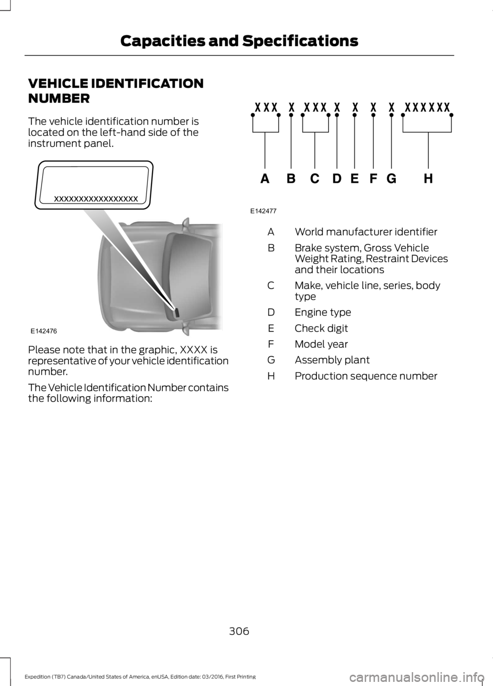
VEHICLE IDENTIFICATION
NUMBER
The vehicle identification number islocated on the left-hand side of theinstrument panel.
Please note that in the graphic, XXXX isrepresentative of your vehicle identificationnumber.
The Vehicle Identification Number containsthe following information:
World manufacturer identifierA
Brake system, Gross VehicleWeight Rating, Restraint Devicesand their locations
B
Make, vehicle line, series, bodytypeC
Engine typeD
Check digitE
Model yearF
Assembly plantG
Production sequence numberH
306
Expedition (TB7) Canada/United States of America, enUSA, Edition date: 03/2016, First Printing
Capacities and SpecificationsE142476 E142477