2017 FIAT TIPO 4DOORS engine
[x] Cancel search: enginePage 111 of 240
IMPORTANT
41)Before moving the gear lever from
position P (Park), bring the ignition device
to position MAR and press the brake pedal.
Otherwise, the gear lever may get
damaged.
42)Engage reverse only with the car
stationary, engine at idling speed and
accelerator fully released.
STOP/START
SYSTEM
(where provided)
The Stop/Start system automatically
stops the engine each time the vehicle
is stationary and starts it again when
the driver wants to move off.
In this way, the vehicle efficiency is
increased, by reducing consumption,
dangerous gas emissions and sound
pollution.
116)
43)
OPERATING MODE
Stopping the engine
Versions with mechanical gearbox
With the vehicle stopped, the engine
stops with gearbox in neutral and clutch
pedal released.
Versions with automatic
transmission
With vehicle at a standstill and brake
pedal pressed, the engine switches off
if the gear lever is in a position other
than R.
The system does not operate when the
gear lever is in R, for making parking
manoeuvres easier.In the event of stops uphill, engine
switching off is disabled to make the
"Hill Hold Control" function available
(works only with running engine).
NOTE the engine can only be
automatically stopped after exceeding a
speed of 10 km/h.
The
warning light on the instrument
panel switches on to signal that the
engine was stopped.
Restarting the engine
Versions with mechanical gearbox
To restart the engine, press the clutch
pedal or the accelerator pedal.
If the vehicle does not start when the
clutch is pressed, place the gear lever
in neutral and repeat the procedure. If
the problem persists, contact a Fiat
Dealership.
Versions with automatic
transmission
To restart the engine, release the brake
pedal.
With brake pressed, if the gear lever is
in automatic mode - D (Drive) - the
engine can be restarted by moving the
lever to R (Reverse) or "AutoStick".
With brake pressed, if the gear lever is
in "AutoStick" mode, the engine can be
restarted by moving the lever to R
(Reverse).
109
Page 112 of 240
When the engine has been stopped
automatically, keeping the brake pedal
pressed, the brake can be released
keeping the engine off by quickly
shifting the gear lever to P (Park).
To restart the engine, just move the
lever out of position P.
SYSTEM MANUAL
ACTIVATION/
DEACTIVATION
To activate/deactivate the system
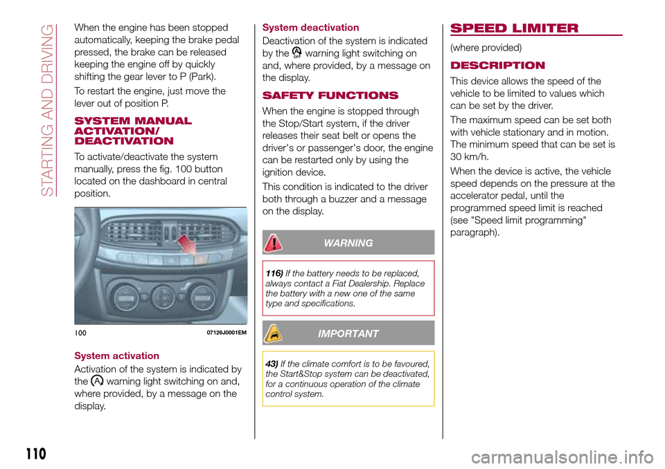
manually, press the fig. 100 button
located on the dashboard in central
position.
System activation
Activation of the system is indicated by
the
warning light switching on and,
where provided, by a message on the
display.System deactivation
Deactivation of the system is indicated
by the
warning light switching on
and, where provided, by a message on
the display.
SAFETY FUNCTIONS
When the engine is stopped through
the Stop/Start system, if the driver
releases their seat belt or opens the
driver's or passenger's door, the engine
can be restarted only by using the
ignition device.
This condition is indicated to the driver
both through a buzzer and a message
on the display.
WARNING
116)If the battery needs to be replaced,
always contact a Fiat Dealership. Replace
the battery with a new one of the same
type and specifications.
IMPORTANT
43)If the climate comfort is to be favoured,
the Start&Stop system can be deactivated,
for a continuous operation of the climate
control system.
SPEED LIMITER
(where provided)
DESCRIPTION
This device allows the speed of the
vehicle to be limited to values which
can be set by the driver.
The maximum speed can be set both
with vehicle stationary and in motion.
The minimum speed that can be set is
30 km/h.
When the device is active, the vehicle
speed depends on the pressure at the
accelerator pedal, until the
programmed speed limit is reached
(see "Speed limit programming"
paragraph).
10007126J0001EM
110
STARTING AND DRIVING
Page 119 of 240
TOWING TRAILERS
IMPORTANT NOTES
122) 123)
For towing caravans or trailers the
vehicle must be fitted with an approved
tow hook and an adequate electrical
system. Should aftermarket installation
be requested, this must be carried out
by specialists.
Install any specific and/or additional
door mirrors as specified by the
Highway Code.
Remember that, when towing a trailer,
steep hills are harder to climb, braking
distances increase and overtaking takes
longer depending on the overall weight
of the trailer.
Engage a low gear when driving
downhill, rather than constantly using
the brake.
The weight the trailer exerts on the
vehicle tow hook reduces the vehicle's
loading capacity by the same amount.
To make sure that the maximum
towable weight is not exceeded (given
in the vehicle registration document)
account should be taken of the fully
laden trailer, including accessories and
luggage.Do not exceed the speed limits specific
to each country you are driving in, in the
case of vehicles towing trailers. In any
case, the top speed must not exceed
100 km/h.
Any electric brake must be powered
directly by the battery through a cable
with a cross-section of no less than
2.5 mm
2.
In addition to the electrical branches,
the vehicle electrical system can only be
connected to the supply cable for an
electric brake and to the cable for an
internal light for the trailer, not
exceeding 15 W. For connections, use
the preset control unit with a battery
cable with section not less than 2.5 mm
2.
IMPORTANT The use of auxiliary loads
other than external lights (e.g. electric
brake) must take place with engine
running.
INSTALLING A TOW
HOOK
The towing device should be fastened
to the body by specialised personnel
according to any additional and/or
integrative information supplied by the
Manufacturer of the device.The towing device must meet current
regulations with reference to Directive
94/20/EC and subsequent
amendments.
For any version the towing device used
must be right for the towable weight of
the vehicle on which it is to be installed.
For the electrical connection a standard
connector should be used which is
generally placed on a special bracket
normally fastened to the towing device,
and a special ECU for external trailer
light control must be installed on the
vehicle.
Seven or thirteen pin 12 V DC
connections should be used
(CUNA/UNI and ISO/DIN Standards).
Follow any instructions provided by the
vehicle manufacturer and/or the towing
device manufacturer.
WARNING
122)The ABS with which the car is
equipped will not control the braking
system of the trailer. Particular caution is
required on slippery roads.
123)Never modify the braking system of
the vehicle to control the trailer brake. The
trailer braking system must be fully
independent of the car’s hydraulic system.
117
Page 120 of 240
REFUELLING THE
VEHICLE
124) 125) 126)
PETROL ENGINES
Only use 95 R.O.N. unleaded petrol (EN
228 specifications).
DIESEL ENGINES
48)
Only use Diesel for motor vehicles
(EN590 specification).
When using or parking the vehicle for a
long time in the mountains or cold
areas, it is advisable to refuel using
locally available Diesel. In this case, it is
also advisable to keep the tank over
50% full.
REFUELLING
PROCEDURE
Diesel and petrol versions
"Capless Fuel" is a device at the
opening for the fuel tank which opens
and recloses automatically when the
fuel supply gun is introduced/removed.
The "Capless Fuel" device is provided
with an inhibitor which prevents
refuelling with incorrect fuel.Opening the flap
To refuel proceed as follows:
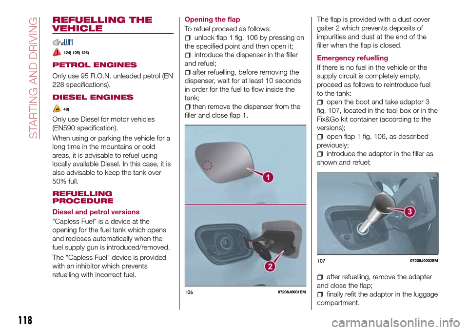
unlock flap 1 fig. 106 by pressing on
the specified point and then open it;
introduce the dispenser in the filler
and refuel;
after refuelling, before removing the
dispenser, wait for at least 10 seconds
in order for the fuel to flow inside the
tank;
then remove the dispenser from the
filler and close flap 1.The flap is provided with a dust cover
gaiter 2 which prevents deposits of
impurities and dust at the end of the
filler when the flap is closed.
Emergency refuelling
If there is no fuel in the vehicle or the
supply circuit is completely empty,
proceed as follows to reintroduce fuel
to the tank:open the boot and take adaptor 3
fig. 107, located in the tool box or in the
Fix&Go kit container (according to the
versions);
open flap 1 fig. 106, as described
previously;
introduce the adaptor in the filler as
shown and refuel;
after refuelling, remove the adapter
and close the flap;
finally refit the adaptor in the luggage
compartment.10607206J0001EM
10707206J0002EM
118
STARTING AND DRIVING
Page 121 of 240
Versions with LPG system
(where provided)
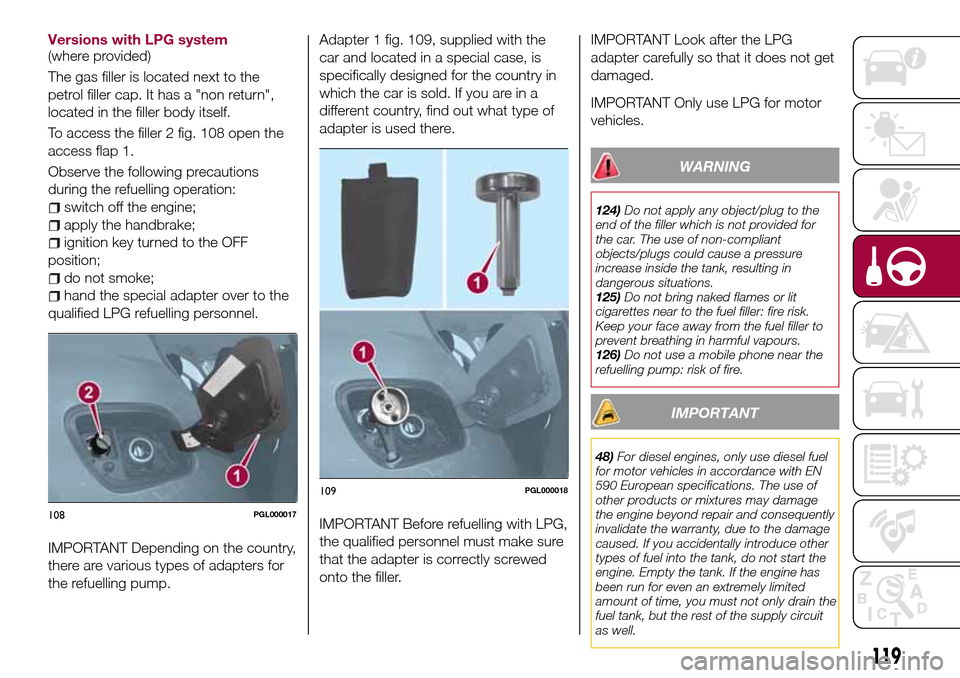
The gas filler is located next to the
petrol filler cap. It has a "non return",
located in the filler body itself.
To access the filler 2 fig. 108 open the
access flap 1.
Observe the following precautions
during the refuelling operation:
switch off the engine;
apply the handbrake;
ignition key turned to the OFF
position;
do not smoke;
hand the special adapter over to the
qualified LPG refuelling personnel.
IMPORTANT Depending on the country,
there are various types of adapters for
the refuelling pump.Adapter 1 fig. 109, supplied with the
car and located in a special case, is
specifically designed for the country in
which the car is sold. If you are in a
different country, find out what type of
adapter is used there.
IMPORTANT Before refuelling with LPG,
the qualified personnel must make sure
that the adapter is correctly screwed
onto the filler.IMPORTANT Look after the LPG
adapter carefully so that it does not get
damaged.
IMPORTANT Only use LPG for motor
vehicles.
WARNING
124)Do not apply any object/plug to the
end of the filler which is not provided for
the car. The use of non-compliant
objects/plugs could cause a pressure
increase inside the tank, resulting in
dangerous situations.
125)Do not bring naked flames or lit
cigarettes near to the fuel filler: fire risk.
Keep your face away from the fuel filler to
prevent breathing in harmful vapours.
126)Do not use a mobile phone near the
refuelling pump: risk of fire.
IMPORTANT
48)For diesel engines, only use diesel fuel
for motor vehicles in accordance with EN
590 European specifications. The use of
other products or mixtures may damage
the engine beyond repair and consequently
invalidate the warranty, due to the damage
caused. If you accidentally introduce other
types of fuel into the tank, do not start the
engine. Empty the tank. If the engine has
been run for even an extremely limited
amount of time, you must not only drain the
fuel tank, but the rest of the supply circuit
as well.
108PGL000017
109PGL000018
119
Page 126 of 240

REPLACING AN
EXTERNAL BULB
Front bulb position
1. Dipped beam headlights
2. Fog lights
3. Main beam headlights/Daytime
running lights (DRL)
4. Direction indicator.Main beam headlights/Daytime
running lights (DRL)
To replace the bulb 3 fig. 111, proceed
as follows:
working from inside the engine
compartment, remove rubber cap 1
fig. 112;
rotate the bulb-bulb holder assembly
anticlockwise and extract it;
disconnect the electrical connector
and replace the bulb-bulb holder
assembly 2;
reconnect the electrical connector to
the new assembly;
then insert the assembly in its
housing and turn it clockwise, making
sure that it is locked correctly;
refit the rubber cap 1.
IMPORTANT Only replace the bulb
when the engine is off. Also ensure that
the engine is cold, to prevent the risk of
burns.
Dipped headlights
Right headlight
To replace the bulb 1 fig. 111, proceed
as follows:
steer the vehicle wheels completely
inwards;
undo screw 1 fig. 113 using the
screwdriver provided and remove
inspection flap 2;
remove the rubber plug
disconnect the electrical connector;
extract the bulb, releasing it from the
retaining springs;
replace the new bulb and carry out
the procedure described previously in
reverse.
11108026J0002EM
11208026J0025EM
113P08026J004
124
IN AN EMERGENCY
Page 127 of 240

Left headlight
working from inside the engine
compartment, remove the rubber cap
from the dipped beam headlight bulb 1
fig. 111;
extract the bulb, releasing it from the
retaining springs;
disconnect the electrical connector
and replace the bulb 1 fig. 111;
reconnect the electrical connector to
the new bulb;
reposition the assembly in the seat;
refit the rubber cap.
IMPORTANT Only replace the bulb
when the engine is off. Also ensure that
the engine is cold, to prevent the risk of
burns.
Front direction indicators
To replace the bulb 4 fig. 111, proceed
as follows:
using the screwdriver provided with
the car, remove the indicated fasteners
and remove the cover 1 fig. 114;
rotate the bulb-bulb holder assembly
anticlockwise;
replace the "bayonet-fitted" bulb;
then insert the bulb-bulb holder
assembly in its housing and turn it
clockwise, making sure that it is locked
correctly;
refit the cover and block it by placing
the fasteners back in position.Front fog lights
To replace the bulbs, proceed as
follows:
steer the vehicle wheels completely
inwards;
undo screw 1 fig. 115 using the
screwdriver provided and remove
inspection flap 2;
11408026J0011EM
115P08026J0012
11608026J0016EM
125
Page 130 of 240
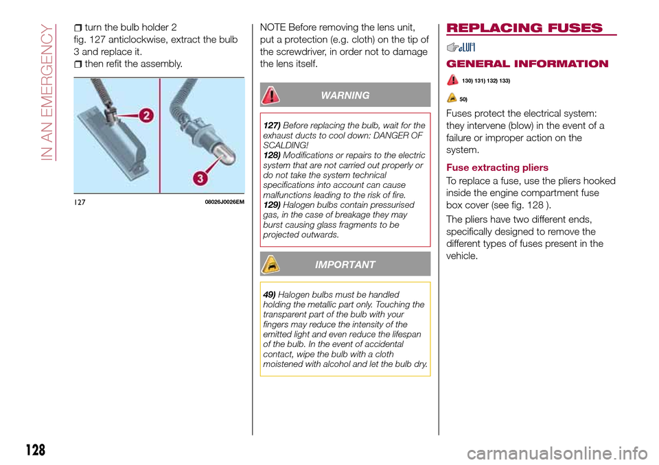
turn the bulb holder 2
fig. 127 anticlockwise, extract the bulb
3 and replace it.
then refit the assembly.NOTE Before removing the lens unit,
put a protection (e.g. cloth) on the tip of
the screwdriver, in order not to damage
the lens itself.
WARNING
127)Before replacing the bulb, wait for the
exhaust ducts to cool down: DANGER OF
SCALDING!
128)Modifications or repairs to the electric
system that are not carried out properly or
do not take the system technical
specifications into account can cause
malfunctions leading to the risk of fire.
129)Halogen bulbs contain pressurised
gas, in the case of breakage they may
burst causing glass fragments to be
projected outwards.
IMPORTANT
49)Halogen bulbs must be handled
holding the metallic part only. Touching the
transparent part of the bulb with your
fingers may reduce the intensity of the
emitted light and even reduce the lifespan
of the bulb. In the event of accidental
contact, wipe the bulb with a cloth
moistened with alcohol and let the bulb dry.
REPLACING FUSES
GENERAL INFORMATION
130) 131) 132) 133)
50)
Fuses protect the electrical system:
they intervene (blow) in the event of a
failure or improper action on the
system.
Fuse extracting pliers
To replace a fuse, use the pliers hooked
inside the engine compartment fuse
box cover (see fig. 128 ).
The pliers have two different ends,
specifically designed to remove the
different types of fuses present in the
vehicle.
12708026J0026EM
128
IN AN EMERGENCY