2017 FIAT QUBO sensor
[x] Cancel search: sensorPage 90 of 260

WARNING
The ultimate responsibility when
parking and carrying out other
dangerous manoeuvres still rests with the
driver.When parking, make sure that no-one is
standing in the area, especially children or
animals. Parking sensors are designed to assist
drivers; however, you must always concentrate
fully during potentially dangerous manoeuvres,
even if carried out at low speeds.
START&STOP SYSTEM
(for versions/markets, where provided)
INTRODUCTION
The Start&Stop device automatically stops the engine
each time the vehicle is stationary and starts it
again when the driver wants to move off. This
improves the efficiency of the vehicle by reducing fuel
consumption, the emission of harmful gases and
noise pollution.
OPERATING MODES
Engine stopping mode
WITH MANUAL GEARBOX
With the vehicle stationary, the engine stops with
the gearbox in neutral and the clutch pedal released.
WITH ROBOTISED GEARBOX
The engine cuts out if the vehicle stops with the
brake pedal pressed.
This condition can be maintained even if the brake
pedal is not depressed, if the gear lever is in position
N.
NoteThe engine can only be stopped automatically
after a speed of about 10 km/h is reached, to prevent
the engine from being repeatedly stopped when
driving at walking pace.
The engine being stopped is signalled by the icon
fig. 95 on the display, depending on the trim level.
86
KNOWING YOUR
VEHICLE
SAFETY
STARTING AND
DRIVING
WARNING LIGHTS
AND MESSAGES
IN AN EMERGENCY
SERVICING AND
CARE
TECHNICAL DATA
INDEX
Page 93 of 260

IRREGULAR OPERATION
In the event of malfunctions the Start&Stop system is
disabled. The driver is informed of the problem by
the switching on of the general failure fig. 97 warning
light A, where provided, an information message
and the system failure fig. 97 icon B on the control
panel.
In this case, contact a Fiat Dealership.
VEHICLE INACTIVITY
In cases of car inactivity, special attention must be
paid due to the disconnection of the battery power
supply. Proceed as follows: disconnect connector
A fig. 98(by pressing button B) from the sensor C for
monitoring the status of the battery installed on
the negative pole D of the battery itself. This sensor
should never be disconnected from the pole except
if the battery is replaced.IMPORTANT After turning the ignition key to STOP,
wait at least 1 minute before disconnecting the
electrical supply to the battery.
WARNING
If the batter y needs to be replaced,
always contact a Fiat Dealership.
Replace the battery with a new one of the
same type and specifications.
EMERGENCY STARTING
In the event of emergency starting fig. 99 with a
booster battery, never connect the negative lead (-)
of the booster battery to the negative pole C of
the vehicle's battery, but rather to an engine/gearbox
earth point (follow the lead connection procedure
described in the "Jump starting" paragraph in the
chapter "In an emergency").
fig. 97F0T0427fig. 98F0T0428
89
KNOWING YOUR
VEHICLE
SAFETY
STARTING AND
DRIVING
WARNING LIGHTS
AND MESSAGES
IN AN EMERGENCY
SERVICING AND
CARE
TECHNICAL DATA
INDEX
Page 100 of 260

PROTECTING THE ENVIRONMENT
The devices for reducing petrol engine emissions are
the following:
three-way catalytic converter
Lambda sensors
anti-evaporation system.
In addition, do not let the engine run, even for a test,
with one or more spark plugs disconnected.
The following devices are used for reducing diesel
fuel engine emissions:
oxidising catalytic converter
exhaust gas recirculation system (EGR)
diesel particulate filter (DPF) (for versions/
markets, where provided).
DIESEL PARTICULATE FILTER (DPF)
(for versions/markets, where provided)
The Diesel Particulate Filter is a mechanical filter,
integral to the exhaust system, that physically traps
carbon particulates present in the exhaust gases
of diesel engines.
It is needed to eliminate almost all particulates in
compliance with current/future legislation. During
normal use of the vehicle, the engine control unit
records a set of data (e.g.: travel time, type of route,
temperatures, etc.) and it will then calculate how
much particulate has been trapped by the filter.Since this filter physically traps particulate, it should
be regenerated (cleaned) at regular intervals by
burning the carbon particles. The regeneration
procedure is controlled automatically by the engine
management control unit according to the filter
conditions and vehicle use conditions.
During regeneration, the following may occur: a
limited increase in the engine speed, activation of the
fan, a limited increase in fumes and high
temperatures at the exhaust.
These are not faults; they do not impair vehicle
performance or damage the environment. If
the dedicated message is displayed, refer to the
“Warning lights and messages” section.
96
KNOWING YOUR
VEHICLE
SAFETY
STARTING AND
DRIVING
WARNING LIGHTS
AND MESSAGES
IN AN EMERGENCY
SERVICING AND
CARE
TECHNICAL DATA
INDEX
Page 146 of 260

GENERIC FAILURE INDICATION
(amber)
The warning light turns on in the following
circumstances:
Engine oil pressure sensor failure
The warning light turns on when an engine oil
pressure sensor failure is detected.
Go to a Fiat Dealership to have the fault fixed as
soon as possible.
Exterior lights fault
The warning light comes on (on some versions)
when a failure is detected in one of the following
lights:
side/tail lights
brake lights
rear fog lights
direction indicators
number plate lights.
The failure relating to these lights could be: one or
more blown bulbs, a blown protection fuse or a
break in the electrical connection.
A specific message is displayed on certain versions.Fuel cut-off inertia switch tripped
The warning light switches on when the fuel cut-off
inertia switch is triggered.
The display will show a dedicated message.
Parking sensor failure
(for versions/markets, where provided)
See parking sensor warning light section.
Start&Stop fault
(for versions/markets, where provided)
The warning light comes on when a Start&Stop
system fault is detected.
Warning light failure
The warning lightturns on and flashes to indicate a
failure of the warning light
. In this case, the
warning light may not indicate a fault in the
restraint systems.
Before continuing, contact a Fiat Dealership
immediately to have the system checked.
142
KNOWING YOUR
VEHICLE
SAFETY
STARTING AND
DRIVING
WARNING LIGHTS
AND MESSAGES
IN AN EMERGENCY
SERVICING AND
CARE
TECHNICAL DATA
INDEX
Page 147 of 260

TPMS (amber)
TPMS failure
The warning light switches on and blinks for approx.
75 seconds, then it stays on constantly, when a
fault is detected in the TPMS.
In this case, contact a Fiat Dealership as soon as
possible.
Tyre pressure low
The warning light switches on to indicate that the
tyre pressure is lower than the recommended value
and/or that a pressure loss is occurring. In these
circumstances, optimal tyre duration and fuel
consumption may not be guaranteed.
BRAKE PAD WEAR (amber)
The warning light goes on if the front brake pads are
worn. In this case replace them as soon as possible.
A specific message is displayed on certain versions.
PARKING SENSOR FAULT (yellow)
(for versions/markets, where provided)
The warning light turns on when a parking sensor
fault is detected.
On certain versions warning light
comes on
instead.
In this case, contact a Fiat Dealership.
A specific message is displayed on certain versions.
ASR SYSTEM DEACTIVATED
(amber)
The ASR system can be turned off by pressing the
button ASR OFF.
The warning light switches on to warn the driver
that the system is off.
If the ASR OFF button is pressed again, the warning
light will switch off to inform the driver that the
system is on again.
143
KNOWING YOUR
VEHICLE
SAFETY
STARTING AND
DRIVING
WARNING LIGHTS
AND MESSAGES
IN AN EMERGENCY
SERVICING AND
CARE
TECHNICAL DATA
INDEX
Page 178 of 260

PROTECTED DEVICE - fig. 173 FUSE AMPS
Air conditioner compressor F19 7.5
Heated rear window, mirror defrosters F20 30
Fuel pump F21 15
Fog lights F08 15
Cigar lighter/Passenger compartment socket/Heated seats F85 30
+15 reverse lights/air flow meter/water in fuel sensor/relay coils T02, T05,
T14, T17 and T19 (1.4 versions)F87 7,5
IBS battery charge sensor for Start&Stop system (1.3 Multijet with
Start&Stop)F87 5
174
KNOWING YOUR
VEHICLE
SAFETY
STARTING AND
DRIVING
WARNING LIGHTS
AND MESSAGES
IN AN
EMERGENCY
SERVICING AND
CARE
TECHNICAL DATA
INDEX
Page 180 of 260

PROTECTED DEVICE - fig. 175 FUSE AMPS
Dipped headlight (passenger side)
F12
(*)7,5
Dipped headlight (driver side)/Headlight alignment corrector F13
7,5/5
(*)
INT/A SCM relay coils F31 5
Timed interior lighting
F32
(*)7,5
Radio
Bluetoothfisystem node/Blue&Me™ node/EOBD diagnostic socket/
Volumetric alarm ECU/Alarm siren ECUF36 10
Instrument panel node/Stop light control (NO) F37 5
Door/luggage compartment lock actuators
(*)F38 20
Windshield washer/rear window washer bidirectional pump F43 15
Front electric window (driver side)
(*)F47 20
Front electric window (passenger side)
(*)F48 20
Control lights/Parking sensors ECU/Electric wing mirrors/Volumetric alarm
ECUF49 5
INT Radio node/
Bluetoothfisystem ECU/Blue&Me™ node/Electric wing
mirrors movement/Clutch switch/
Brake light control (NC)F51 7.5
Instrument panel node F53 5
External mirror defrosters F41 7.5
SpareF45 -
SpareF46 -
SpareF90 -
(*)For versions/markets, where provided
176
KNOWING YOUR
VEHICLE
SAFETY
STARTING AND
DRIVING
WARNING LIGHTS
AND MESSAGES
IN AN
EMERGENCY
SERVICING AND
CARE
TECHNICAL DATA
INDEX
Page 182 of 260

RECHARGING THE BATTERY
IMPORTANT The battery recharging procedure is
provided for information purposes only. You are
recommended to go to a Fiat Dealership to have this
operation performed.
We recommend recharging the battery slowly for
approximately 24 hours at low amperage. A
prolonged recharge might damage the battery.
Charge the battery as follows:
without Start&Stop system:
disconnect battery negative terminal;
connect the charger cables to the battery
terminals, observing the polarity;
turn on the charger;
when you have finished, turn the charger off
before disconnecting it from the battery;
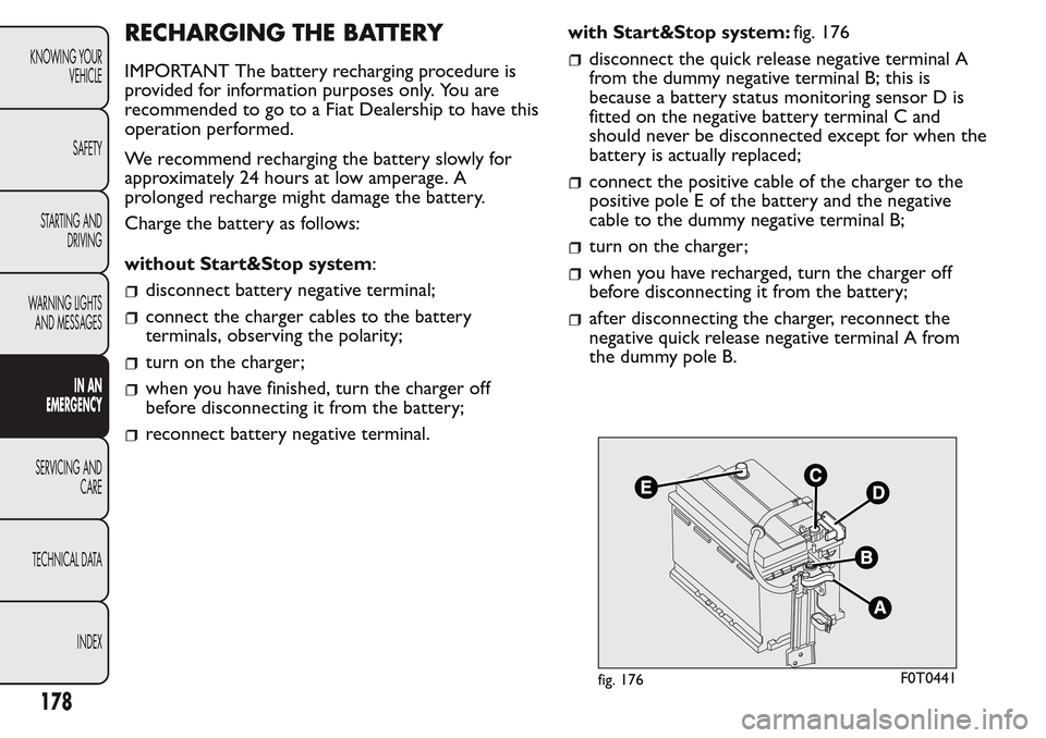
reconnect battery negative terminal.with Start&Stop system:fig. 176
disconnect the quick release negative terminal A
from the dummy negative terminal B; this is
because a battery status monitoring sensor D is
fitted on the negative battery terminal C and
should never be disconnected except for when the
battery is actually replaced;
connect the positive cable of the charger to the
positive pole E of the battery and the negative
cable to the dummy negative terminal B;
turn on the charger;
when you have recharged, turn the charger off
before disconnecting it from the battery;
after disconnecting the charger, reconnect the
negative quick release negative terminal A from
the dummy pole B.
fig. 176F0T0441
178
KNOWING YOUR
VEHICLE
SAFETY
STARTING AND
DRIVING
WARNING LIGHTS
AND MESSAGES
IN AN
EMERGENCY
SERVICING AND
CARE
TECHNICAL DATA
INDEX