2017 FIAT FIORINO key
[x] Cancel search: keyPage 19 of 272

IGNITION SWITCH
The key can be turned to 3 different positions fig. 11:
STOP: engine off, key extractable, steering
locked. Some electrical devices (e.g. car radio,
central door locking system, alarm, etc.) can work.
MAR: driving position. All electrical devices can
work.
AVV: starting the engine. The ignition switch is
fitted with an electronic safety system that
requires the ignition key to be turned back to
STOP if the engine does not start, before the
starting operation can be repeated.
STEERING LOCK
Engagement
When the key is at STOP, remove the key and turn
the steering wheel until it locks.Disengagement
Move the steering wheel slightly as you turn the
ignition key to MAR.
WARNING
Never extract the key while the vehicle
is moving.The steering wheel should lock
automatically as soon as it is turned.This also
applies to cases in which the vehicle is towed. It
is absolutely forbidden to carr y out any
after-market operation involving steering
system or steering column modifications (e.g.
installation of anti-theft device) that could
badly affect performance and safety, invalidate
the warranty and also result in the car failing
to comply with regulations.
fig. 11F0T0039
15
KNOWING YOUR
VEHICLE
SAFETY
STARTING AND
DRIVING
WARNING LIGHTS
AND MESSAGES
IN AN EMERGENCY
SERVICING AND
CARE
TECHNICAL DATA
INDEX
Page 22 of 272

DIGITAL DISPLAY
STANDARD SCREEN
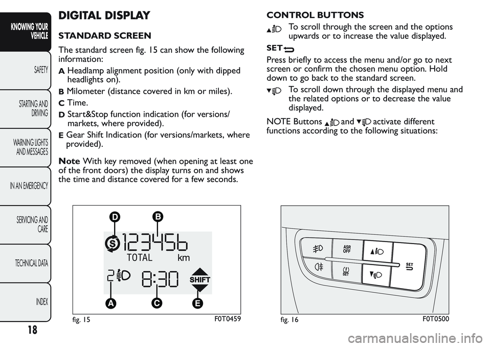
The standard screen fig. 15 can show the following
information:
AHeadlamp alignment position (only with dipped
headlights on).
BMilometer (distance covered in km or miles).
CTime.
DStart&Stop function indication (for versions/
markets, where provided).
EGear Shift Indication (for versions/markets, where
provided).
NoteWith key removed (when opening at least one
of the front doors) the display turns on and shows
the time and distance covered for a few seconds.CONTROL BUTTONS
To scroll through the screen and the options
upwards or to increase the value displayed.
SET
Press briefly to access the menu and/or go to next
screen or confirm the chosen menu option. Hold
down to go back to the standard screen.
To scroll down through the displayed menu and
the related options or to decrease the value
displayed.
NOTE Buttons
andactivate different
functions according to the following situations:
fig. 15F0T0459fig. 16F0T0500
18
KNOWING YOUR
VEHICLE
SAFETY
STARTING AND
DRIVING
WARNING LIGHTS
AND MESSAGES
IN AN EMERGENCY
SERVICING AND
CARE
TECHNICAL DATA
INDEX
Page 36 of 272

To set the desired volume, proceed as follows:
- briefly press theSET
button, the previously set
volume “level” will flash on the display;
- press the
orbutton to adjust;
- press theSET
button briefly to go back to the
menu screen or hold the button down to go back
to the standard screen without saving.
Reactivation of buzzer for S.B.R. signal (Belt
buzzer)
This function can be displayed only after a Fiat
Dealership has deactivated the SBR system (see "SBR
system" in the "Safety" section).
Scheduled Servicing (Service)
Using this function you can display information about
the mileage intervals for vehicle servicing.
To consult the information, proceed as follows:
- press theSET
button briefly: the display will
show when servicing is due in km or mi according to
the previous setting (see paragraph "Units of
measurement");
- briefly press theSET
button to go back to the
menu screen or hold the button down to go back
to the standard screen.NoteThe "Scheduled Servicing Plan" includes vehicle
maintenance at fixed intervals, refer to the
"Maintenance and care" chapter. The indication of
the "Service" function will appear automatically, with
the key in MAR position, starting from 2,000 km
(or 1,240 mi) and will be displayed every 200 km (or
124 mi).
Below 200 km servicing indications are more
frequent. The display will be in km or miles according
to the unit of measurement set. When the next
service is close, when the ignition is turned ON the
word "Service" appears in the display followed by
the remaining number of kilometres/miles. Go to a
Fiat Dealership, where the "Scheduled Service Plan"
operations will be performed and the message
will be reset.
Passenger airbag and side bag activation/
deactivation (Passenger bag)
(for versions/markets, where provided)
This function allows the passenger side airbag to be
activated/deactivated.
Proceed as follows:- press the SETbutton and, after the display
shows the message (Passenger bag: Off ) (to
deactivate) or the message (Passenger Bag: On)
(to activate) by pressing the
andbuttons,
press the SET
button again;
the confirmation request message will appear on
the display;
32
KNOWING YOUR
VEHICLE
SAFETY
STARTING AND
DRIVING
WARNING LIGHTS
AND MESSAGES
IN AN EMERGENCY
SERVICING AND
CARE
TECHNICAL DATA
INDEX
Page 37 of 272

press buttonsorto select (Yes)
(confirming activation/deactivation) or (No) (to
abort);
press the SETbutton button briefly: a message
confirming the selection will be displayed and you
will return to the menu screen or, pressing the
button for longer, you will return to the standard
screen without saving.
Exit Menu
This is the last function that closes the cycle of
settings listed in the menu screen.
Pressing theSET
button briefly will return the
display to the standard screen without storing.
Press button
to return to the first menu item on
the display (Speed Beep).
TRIP COMPUTER
General features
The Trip computer is used to display information on
vehicle operation when the ignition key is turned
to MAR. This function allows you to define two
separate trips, called "Trip A" and "Trip B", for
monitoring the "complete mission" (journey) of the
vehicle in a reciprocally independent manner. Both
functions can be reset (start of a new journey).
“Trip A” is used to display the values relating to:
Outside temperature (for Natural Power vehicles
equipped with temperature sensor)
Range
Distance travelled
Average consumption
Current consumption
Average speed
Travel time (driving time).
"Trip B", available on multifunction display only, is
used to display the values relating to:
Distance travelled B
Average consumption B
Average speed B
Travel time B (driving time).
33
KNOWING YOUR
VEHICLE
SAFETY
STARTING AND
DRIVING
WARNING LIGHTS
AND MESSAGES
IN AN EMERGENCY
SERVICING AND
CARE
TECHNICAL DATA
INDEX
Page 38 of 272

“Trip B” may be disabled (see “Activating
Trip B”). “Range” and “Instant
consumption" parameters cannot be
reset .
Values displayed
Range (for versions/markets where provided)
This value shows the distance that the car can still
cover before needing fuel, assuming that driving style
is unvaried. “----”will appear on the display in
the following cases:
range is lower than 50 km (or 30 mi)
vehicle is left parked with the engine running for a
long time.
IMPORTANT The range can be affected by several
factors: driving style (see “Driving style” in the
“Starting and driving” section), type of route
(motorway, towns and cities, mountain roads, etc.),
conditions of use (load, tyre pressures, etc.). Trip
planning must therefore take the above into account.
Distance travelled
This value shows the distance covered from the start
of the new journey.
Average consumption
This value shows the approximate average fuel
consumption from the start of the new journey.Current consumption
This value shows the fuel consumption. The value is
constantly updated. The message “----” will appear
on the display if the vehicle is parked with the engine
running.
Average speed
Shows the average speed of the vehicle by using the
overall time elapsed since the start of a new journey.
Journey time
Time elapsed since the start of the new journey.
IMPORTANT If there is no information, the Trip
computer displays "----" in place of the value. When
normal operating conditions are restored, the
counting of the various values is resumed, without
either zeroing the values displayed prior to the
problem, or starting a new journey.
Control TRIP button
The TRIP button is located at the end of the right
stalk fig. 22. With the ignition key turned to
MAR-ON, this button allows you to view the
previously described values and also zero them to
begin a new journey:
press briefly to display the different values;
long push to reset and then start a new journey.
This begins after a reset:
34
KNOWING YOUR
VEHICLE
SAFETY
STARTING AND
DRIVING
WARNING LIGHTS
AND MESSAGES
IN AN EMERGENCY
SERVICING AND
CARE
TECHNICAL DATA
INDEX
Page 39 of 272

“manual” resetting by the user, by pressing the
relevant button;
automatically when the distance travelled reaches
9,999.9 km (miles) or when the journey time
reaches 99.59:59 (99 hours and 59 minutes);
disconnection/reconnection of the battery.
IMPORTANT The reset operation when “Trip A”
details are being displayed only resets the
information associated with this function.
IMPORTANT The reset operation when “Trip B”
details are being displayed resets only the
information associated with this function.
With ignition key at MAR, press and hold the TRIP
button for more than 2 seconds to reset.Exit Trip
The TRIP function ends automatically once all the
values have been displayed or by holding theSET
button down for more than 1 second.
fig. 22F0T0038
35
KNOWING YOUR
VEHICLE
SAFETY
STARTING AND
DRIVING
WARNING LIGHTS
AND MESSAGES
IN AN EMERGENCY
SERVICING AND
CARE
TECHNICAL DATA
INDEX
Page 40 of 272

SEATS
FRONT SEATS
WARNING
All adjustments must be made with the
vehicle stationary.
Lengthwise adjustment
Lift lever A fig. 23and push the seat forwards or
backwards: in the driving position your arms should
rest on the rim of the steering wheel.
WARNING
Once you have released the adjustment
lever, always check that the seat is
locked on the guides by trying to move it back
and forth. If it is not locked, the seat may move
unexpectedly and make you lose control of
the vehicle.
Backrest angle adjustment
Turn knob B fig. 23.
Height adjustment (driver only)
(for versions/markets, where provided)
Operate lever C fig. 23 to lift or lower the rear part
of the cushion to achieve the most comfortable
driving position.
IMPORTANT Adjustment must be carried out only
when seated in the relevant seat.
Driver seat lumbar adjustment
(for versions/markets, where provided)
Turn knob D fig. 23 to adjust the backrest support.
Seat heating
(for versions/markets, where provided)
With the key turned to MAR, press button A fig. 24
to switch the function on/off.
B
D
C
A
fig. 23F0T0153
36
KNOWING YOUR
VEHICLE
SAFETY
STARTING AND
DRIVING
WARNING LIGHTS
AND MESSAGES
IN AN EMERGENCY
SERVICING AND
CARE
TECHNICAL DATA
INDEX
Page 48 of 272

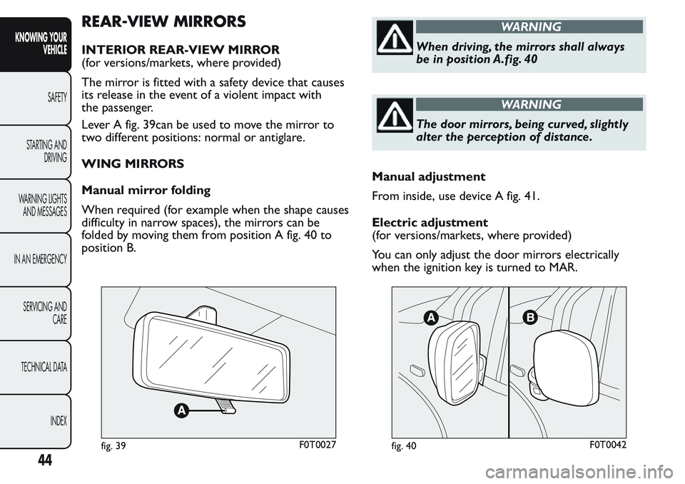
REAR-VIEW MIRRORS
INTERIOR REAR-VIEW MIRROR
(for versions/markets, where provided)
The mirror is fitted with a safety device that causes
its release in the event of a violent impact with
the passenger.
Lever A fig. 39can be used to move the mirror to
two different positions: normal or antiglare.
WING MIRRORS
Manual mirror folding
When required (for example when the shape causes
difficulty in narrow spaces), the mirrors can be
folded by moving them from position A fig. 40 to
position B.
WARNING
When driving, the mirrors shall always
be in position A.fig. 40
WARNING
The door mirrors, being curved, slightly
alter the perception of distance.
Manual adjustment
From inside, use device A fig. 41.
Electric adjustment
(for versions/markets, where provided)
You can only adjust the door mirrors electrically
when the ignition key is turned to MAR.
fig. 39F0T0027fig. 40F0T0042
44
KNOWING YOUR
VEHICLE
SAFETY
STARTING AND
DRIVING
WARNING LIGHTS
AND MESSAGES
IN AN EMERGENCY
SERVICING AND
CARE
TECHNICAL DATA
INDEX