2017 FIAT 500L LIVING buttons
[x] Cancel search: buttonsPage 9 of 240
DASHBOARD
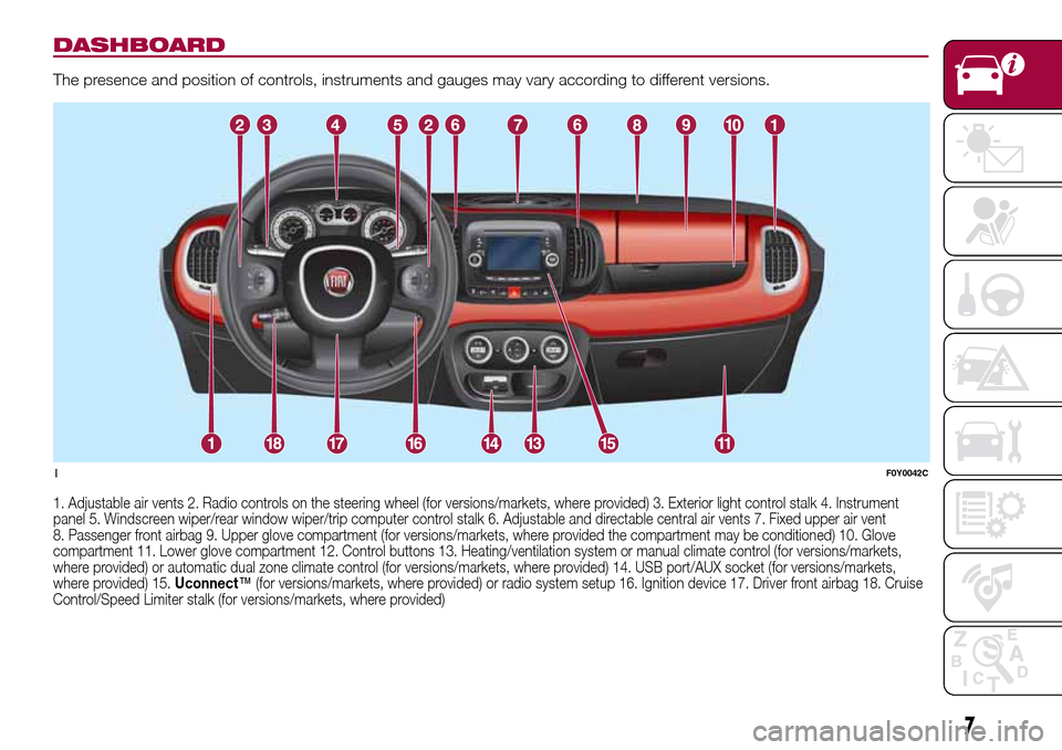
The presence and position of controls, instruments and gauges may vary according to different versions.
1. Adjustable air vents 2. Radio controls on the steering wheel (for versions/markets, where provided) 3. Exterior light control stalk 4. Instrument
panel 5. Windscreen wiper/rear window wiper/trip computer control stalk 6. Adjustable and directable central air vents 7. Fixed upper air vent
8. Passenger front airbag 9. Upper glove compartment (for versions/markets, where provided the compartment may be conditioned) 10. Glove
compartment 11. Lower glove compartment 12. Control buttons 13. Heating/ventilation system or manual climate control (for versions/markets,
where provided) or automatic dual zone climate control (for versions/markets, where provided) 14. USB port/AUX socket (for versions/markets,
where provided) 15.Uconnect™(for versions/markets, where provided) or radio system setup 16. Ignition device 17. Driver front airbag 18. Cruise
Control/Speed Limiter stalk (for versions/markets, where provided)
1F0Y0042C
7
Page 16 of 240
REMOVAL
To remove head restraints, lift them to
the max. height, press buttons A and B
fig. 15 (front head restraints) or A and
B fig. 16 (rear head restraints) at the
side of the two supports, then remove
the head restraints by pulling them
upwards.
IMPORTANT If the rear seats are used,
always set the head restraints in the
"completely raised" position.
WARNING
16)The head restraints must be adjusted
so that the head, rather than the neck,
rests on them. Only in this case can they
protect your head correctly.
STEERING WHEEL
17) 18)
ADJUSTMENTS
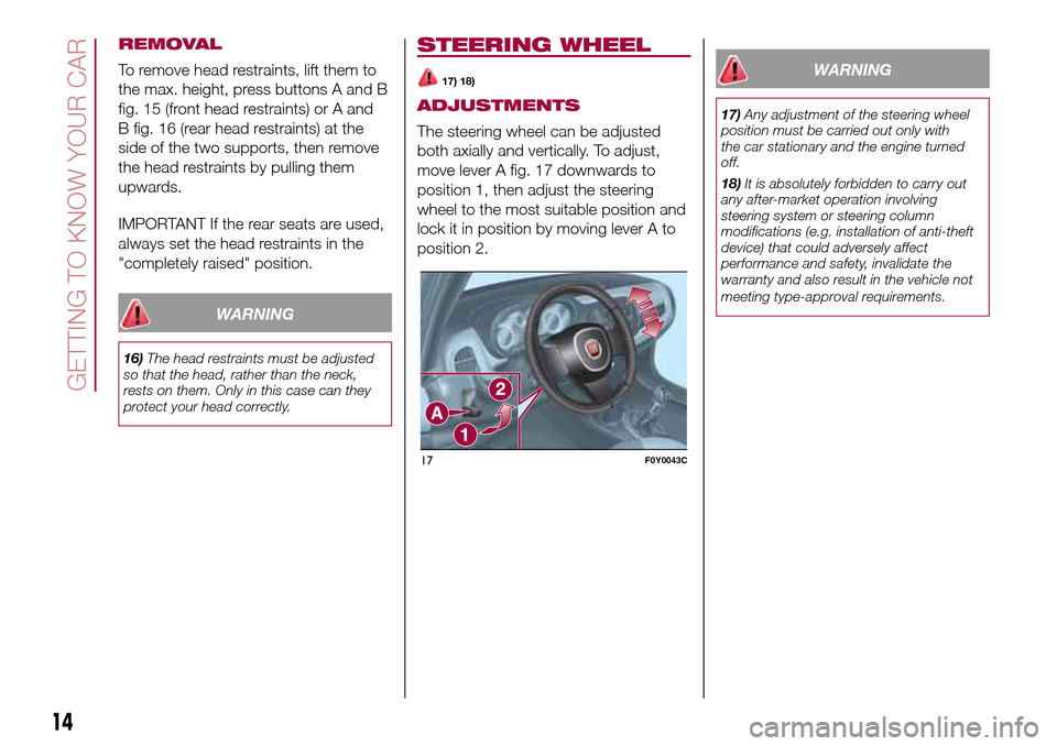
The steering wheel can be adjusted
both axially and vertically. To adjust,
move lever A fig. 17 downwards to
position 1, then adjust the steering
wheel to the most suitable position and
lock it in position by moving lever A to
position 2.
WARNING
17)Any adjustment of the steering wheel
position must be carried out only with
the car stationary and the engine turned
off.
18)It is absolutely forbidden to carry out
any after-market operation involving
steering system or steering column
modifications (e.g. installation of anti-theft
device) that could adversely affect
performance and safety, invalidate the
warranty and also result in the vehicle not
meeting type-approval requirements.
17F0Y0043C
14
GETTING TO KNOW YOUR CAR
Page 20 of 240
AUTOMATIC DUAL-ZONE CLIMATE CONTROL SYSTEM
19)5)
Controls
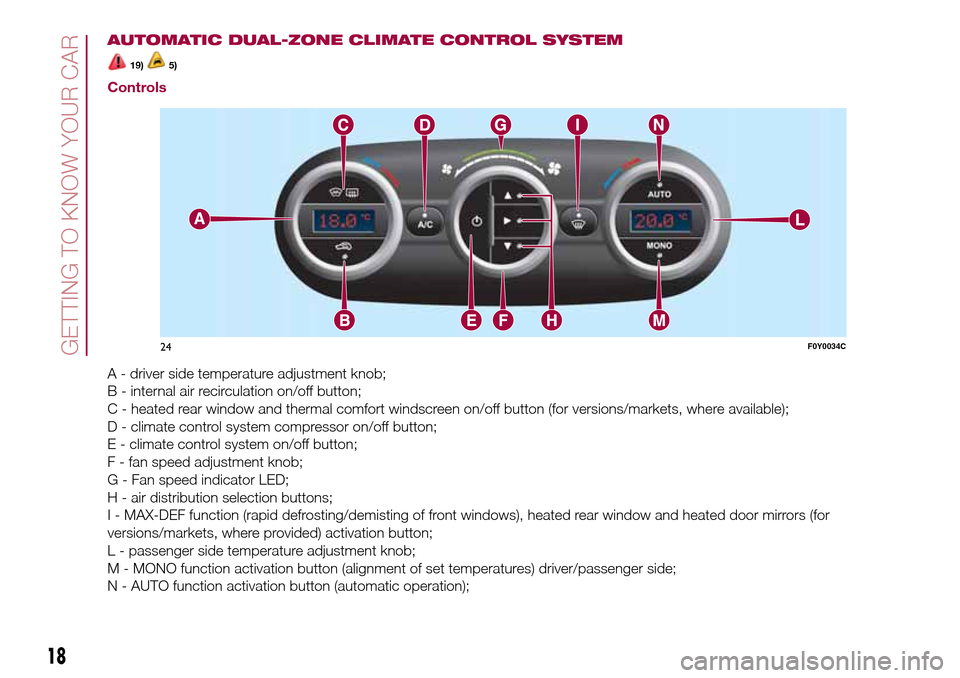
A - driver side temperature adjustment knob;
B - internal air recirculation on/off button;
C - heated rear window and thermal comfort windscreen on/off button (for versions/markets, where available);
D - climate control system compressor on/off button;
E - climate control system on/off button;
F - fan speed adjustment knob;
G - Fan speed indicator LED;
H - air distribution selection buttons;
I - MAX-DEF function (rapid defrosting/demisting of front windows), heated rear window and heated door mirrors (for
versions/markets, where provided) activation button;
L - passenger side temperature adjustment knob;
M - MONO function activation button (alignment of set temperatures) driver/passenger side;
N - AUTO function activation button (automatic operation);
24F0Y0034C
18
GETTING TO KNOW YOUR CAR
Page 26 of 240
EMERGENCY OPERATION
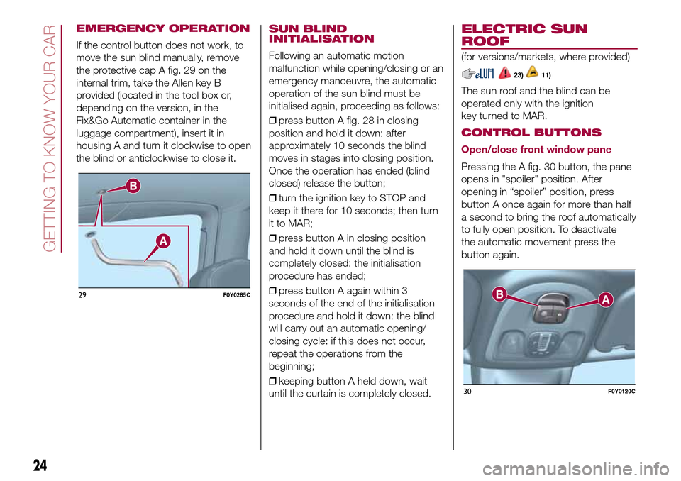
If the control button does not work, to
move the sun blind manually, remove
the protective cap A fig. 29 on the
internal trim, take the Allen key B
provided (located in the tool box or,
depending on the version, in the
Fix&Go Automatic container in the
luggage compartment), insert it in
housing A and turn it clockwise to open
the blind or anticlockwise to close it.
SUN BLIND
INITIALISATION
Following an automatic motion
malfunction while opening/closing or an
emergency manoeuvre, the automatic
operation of the sun blind must be
initialised again, proceeding as follows:
❒press button A fig. 28 in closing
position and hold it down: after
approximately 10 seconds the blind
moves in stages into closing position.
Once the operation has ended (blind
closed) release the button;
❒turn the ignition key to STOP and
keep it there for 10 seconds; then turn
it to MAR;
❒press button A in closing position
and hold it down until the blind is
completely closed: the initialisation
procedure has ended;
❒press button A again within 3
seconds of the end of the initialisation
procedure and hold it down: the blind
will carry out an automatic opening/
closing cycle: if this does not occur,
repeat the operations from the
beginning;
❒keeping button A held down, wait
until the curtain is completely closed.
ELECTRIC SUN
ROOF
(for versions/markets, where provided)
23)11)
The sun roof and the blind can be
operated only with the ignition
key turned to MAR.
CONTROL BUTTONS
Open/close front window pane
Pressing the A fig. 30 button, the pane
opens in "spoiler" position. After
opening in “spoiler” position, press
button A once again for more than half
a second to bring the roof automatically
to fully open position. To deactivate
the automatic movement press the
button again.
29F0Y0285C
30F0Y0120C
24
GETTING TO KNOW YOUR CAR
Page 27 of 240
From the fully open position press
button A: the front glass pane will move
into the "spoiler" position. In this
condition, pressing the button again for
more than half a second, the roof will
automatically move the fully closed
position. To deactivate the automatic
movement press the button again.
Sun blind movement
Pressing the B fig. 30 button: the blind
will move towards the rear part of the
vehicle, until it is fully open. With blind
fully open press button B: the blind
will move towards the front part of the
vehicle, until it is fully closed. During the
blind automatic opening and closing
stages, press the button again to
interrupt the blind movement.
EMERGENCY OPERATION
In the case of control buttons operation
failure, the sun blind and the sun roof
can be moved manually, proceeding as
described below:
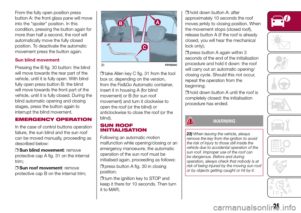
❒Sun blind movement: remove
protective cap A fig. 31 on the internal
trim;
❒Sun roof movement: remove
protective cap B on the internal trim;❒take Allen key C fig. 31 from the tool
box or, depending on the version,
from the Fix&Go Automatic container,
insert it in housing A (for blind
movement) or B (for sun roof
movement) and turn it clockwise to
open the roof (or the blind) or
anticlockwise to close the roof (or the
blind).SUN ROOF
INITIALISATION
Following an automatic motion
malfunction while opening/closing or an
emergency manoeuvre, the automatic
operation of the sun roof must be
initialised again, proceeding as follows:
❒press button A fig. 30 in closing
position;
❒turn the ignition key to STOP and
keep it there for 10 seconds. Then turn
it to MAR;❒hold down button A: after
approximately 10 seconds the roof
moves jerkily to closing position. When
the movement stops (closed roof),
release button A (if the roof is already
closed, you will hear the mechanical
lock only);
❒press button A again within 3
seconds of the end of the initialisation
procedure and hold it down: the roof
will carry out an automatic opening/
closing cycle. Should this not occur,
repeat the operation from the
beginning;
❒hold down button A until the roof is
completely closed: the initialisation
procedure has ended.
WARNING
23)When leaving the vehicle, always
remove the key from the ignition to avoid
the risk of injury to those still inside the
vehicle due to accidental operation of the
sun roof. Improper use of the roof can
be dangerous. Before and during
operation, always check that nobody is at
risk of being injured by the moving sun roof
or by objects getting caught or hit by it.
31F0Y0234C
25
Page 30 of 240
ELECTRIC WINDOWS
25)
OPERATION
These operate when the ignition key is
turned to MAR and for about 3 minutes
after turning the key to STOP or
removing it unless one of the front
doors is open.
DRIVE SIDE FRONT
DOOR CONTROLS
Versions with 4 electric windows
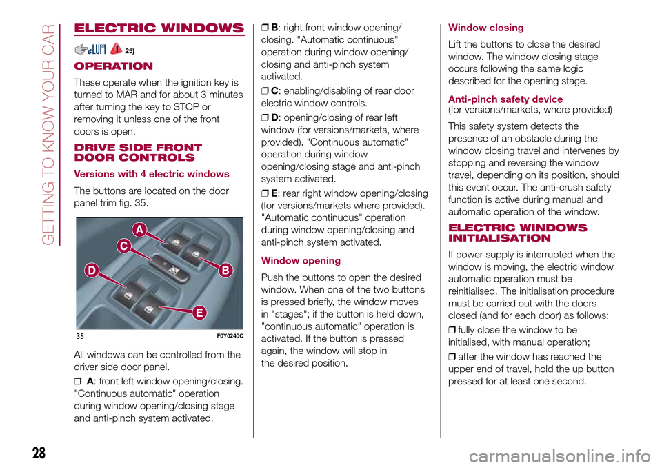
The buttons are located on the door
panel trim fig. 35.
All windows can be controlled from the
driver side door panel.
❒A: front left window opening/closing.
"Continuous automatic" operation
during window opening/closing stage
and anti-pinch system activated.❒B: right front window opening/
closing. "Automatic continuous"
operation during window opening/
closing and anti-pinch system
activated.
❒C: enabling/disabling of rear door
electric window controls.
❒D: opening/closing of rear left
window (for versions/markets, where
provided). "Continuous automatic"
operation during window
opening/closing stage and anti-pinch
system activated.
❒E: rear right window opening/closing
(for versions/markets where provided).
"Automatic continuous" operation
during window opening/closing and
anti-pinch system activated.
Window opening
Push the buttons to open the desired
window. When one of the two buttons
is pressed briefly, the window moves
in "stages"; if the button is held down,
"continuous automatic" operation is
activated. If the button is pressed
again, the window will stop in
the desired position.
Window closing
Lift the buttons to close the desired
window. The window closing stage
occurs following the same logic
described for the opening stage.
Anti-pinch safety device(for versions/markets, where provided)
This safety system detects the
presence of an obstacle during the
window closing travel and intervenes by
stopping and reversing the window
travel, depending on its position, should
this event occur. The anti-crush safety
function is active during manual and
automatic operation of the window.
ELECTRIC WINDOWS
INITIALISATION
If power supply is interrupted when the
window is moving, the electric window
automatic operation must be
reinitialised. The initialisation procedure
must be carried out with the doors
closed (and for each door) as follows:
❒fully close the window to be
initialised, with manual operation;
❒after the window has reached the
upper end of travel, hold the up button
pressed for at least one second.
35F0Y0240C
28
GETTING TO KNOW YOUR CAR
Page 44 of 240
DISPLAY
MULTIFUNCTION
DISPLAY
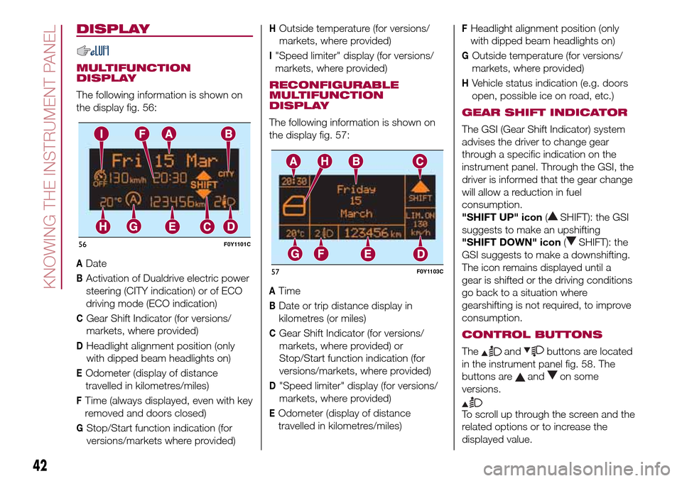
The following information is shown on
the display fig. 56:
ADate
BActivation of Dualdrive electric power
steering (CITY indication) or of ECO
driving mode (ECO indication)
CGear Shift Indicator (for versions/
markets, where provided)
DHeadlight alignment position (only
with dipped beam headlights on)
EOdometer (display of distance
travelled in kilometres/miles)
FTime (always displayed, even with key
removed and doors closed)
GStop/Start function indication (for
versions/markets where provided)
HOutside temperature (for versions/
markets, where provided)
I"Speed limiter" display (for versions/
markets, where provided)
RECONFIGURABLE
MULTIFUNCTION
DISPLAY
The following information is shown on
the display fig. 57:
ATime
BDate or trip distance display in
kilometres (or miles)
CGear Shift Indicator (for versions/
markets, where provided) or
Stop/Start function indication (for
versions/markets, where provided)
D"Speed limiter" display (for versions/
markets, where provided)
EOdometer (display of distance
travelled in kilometres/miles)
FHeadlight alignment position (only
with dipped beam headlights on)
GOutside temperature (for versions/
markets, where provided)
HVehicle status indication (e.g. doors
open, possible ice on road, etc.)
GEAR SHIFT INDICATOR
The GSI (Gear Shift Indicator) system
advises the driver to change gear
through a specific indication on the
instrument panel. Through the GSI, the
driver is informed that the gear change
will allow a reduction in fuel
consumption.
"SHIFT UP" icon(
SHIFT): the GSI
suggests to make an upshifting
"SHIFT DOWN" icon(
SHIFT): the
GSI suggests to make a downshifting.
The icon remains displayed until a
gear is shifted or the driving conditions
go back to a situation where
gearshifting is not required, to improve
consumption.
CONTROL BUTTONS
Theandbuttons are located
in the instrument panel fig. 58. The
buttons are
andon some
versions.
To scroll up through the screen and the
related options or to increase the
displayed value.
56F0Y1101C
57F0Y1103C
42
KNOWING THE INSTRUMENT PANEL
Page 45 of 240
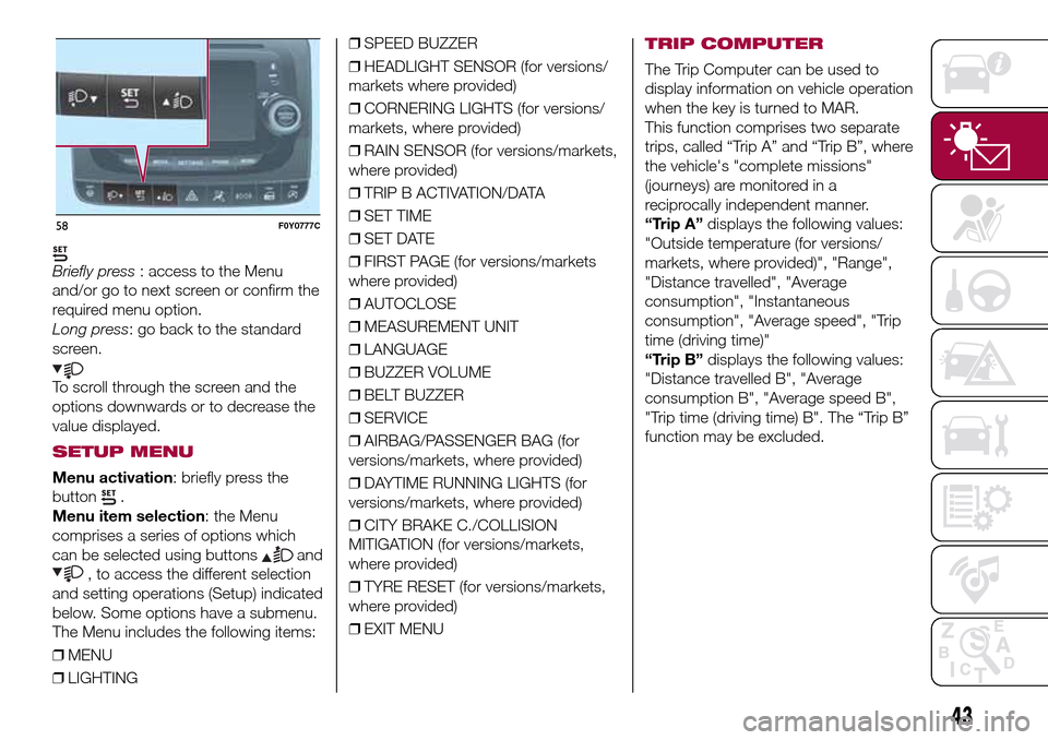
Briefly press: access to the Menu
and/or go to next screen or confirm the
required menu option.
Long press: go back to the standard
screen.
To scroll through the screen and the
options downwards or to decrease the
value displayed.
SETUP MENU
Menu activation: briefly press the
button
.
Menu item selection: the Menu
comprises a series of options which
can be selected using buttons
and
, to access the different selection
and setting operations (Setup) indicated
below. Some options have a submenu.
The Menu includes the following items:
❒MENU
❒LIGHTING❒SPEED BUZZER
❒HEADLIGHT SENSOR (for versions/
markets where provided)
❒CORNERING LIGHTS (for versions/
markets, where provided)
❒RAIN SENSOR (for versions/markets,
where provided)
❒TRIP B ACTIVATION/DATA
❒SET TIME
❒SET DATE
❒FIRST PAGE (for versions/markets
where provided)
❒AUTOCLOSE
❒MEASUREMENT UNIT
❒LANGUAGE
❒BUZZER VOLUME
❒BELT BUZZER
❒SERVICE
❒AIRBAG/PASSENGER BAG (for
versions/markets, where provided)
❒DAYTIME RUNNING LIGHTS (for
versions/markets, where provided)
❒CITY BRAKE C./COLLISION
MITIGATION (for versions/markets,
where provided)
❒TYRE RESET (for versions/markets,
where provided)
❒EXIT MENU
TRIP COMPUTER
The Trip Computer can be used to
display information on vehicle operation
when the key is turned to MAR.
This function comprises two separate
trips, called “Trip A” and “Trip B”, where
the vehicle's "complete missions"
(journeys) are monitored in a
reciprocally independent manner.
“Trip A”displays the following values:
"Outside temperature (for versions/
markets, where provided)", "Range",
"Distance travelled", "Average
consumption", "Instantaneous
consumption", "Average speed", "Trip
time (driving time)"
“Trip B”displays the following values:
"Distance travelled B", "Average
consumption B", "Average speed B",
"Trip time (driving time) B". The “Trip B”
function may be excluded.
58F0Y0777C
43