2017 FIAT 500L LIVING light
[x] Cancel search: lightPage 97 of 240
WARNING
102)Never leave children unattended in
the vehicle. Always remove the key from
the ignition device when leaving the vehicle
and take it with you.
103)For vehicles equipped with a front
armrest, lift it up to ensure that it does not
interfere with the action of the handbrake.
USING THE MANUAL
GEARBOX
104)56)
To engage the gears, press the clutch
pedal fully and put the gear lever into
the required position (the diagram
for gear engagement is shown on the
knob ).
Reverse engagement
For 0.9 TwinAir Turbo 105 HP and 1.4
16V versions: to engage reverse R from
neutral, lift the ring A fig. 90 under the
knob and shift the lever to the right and
back.
For 1.3 16v MultiJet version: to engage
reverse R from neutral position, shift
the lever to the right and then back.For 1.6 16V MultiJet version: to engage
reverse R from neutral, lift ring A under
the knob and at the same time move
the lever to the left and then forwards.
To engage the 6
thgear (for versions/
markets where provided), push firmly to
the right when operating the lever in
order to avoid engaging the 4
thgear by
mistake. The same applies to the shift
from 6
thto 5thgear.
IMPORTANT Reverse can only be
engaged when the vehicle is completely
stationary. With the engine running,
wait for at least 2 seconds with the
clutch pedal fully pressed before
engaging reverse to prevent damage to
the gears and grating.
IMPORTANT The clutch pedal should
be used only for gear changes. Do
not drive with your foot resting on the
clutch pedal, however lightly. For
versions/markets where provided, the
electronic clutch pedal control could cut
in, interpreting the incorrect driving
style as a fault.
90F0Y0136C
95
Page 98 of 240
WARNING
104)Depress the clutch pedal fully to
change gear correctly. Therefore, the floor
area underneath the pedal unit must not
be obstructed in any way. Ensure that the
floor mat is always laid flat and does not
interfere with use of the pedals.
WARNING
56)Do not drive with your hand resting on
the gear lever as the force exerted, even
if slight, could lead over time to premature
wear of the gearbox internal components.
USING THE
DUALOGIC
GEARBOX
(for versions/markets, where provided)
105)57)
GEAR LEVER
The gear lever A fig. 91 is the
multistable floating type, in other words
it has three stable and three unstable
positions.
The three stable positions correspond
to neutral (N), reverse (R) and the
central position located between the
unstable positions (+) and (-).The unstable positions, in other words
those that are abandoned as soon
as the lever is released, are the
positions for requesting a higher gear
(+), requesting a lower gear (–) and
requesting automatic operating mode
(A/M).
IMPORTANT With the engine started,
any error between the lever position
and the gear actually engaged is
signalled by a buzzer until consistency
is restored.
OPERATING MODE
The gearbox/transmission can function
in two operating modes:
❒MANUAL in which the driver decides
when to change gear;
❒AUTO in which the system decides
when to change gear.
MANUAL MODE
Proceed as follows:
❒press the brake pedal and start the
engine;
❒if AUTO is displayed, move the gear
lever A fig. 91 to A/M to select
MANUAL mode;
❒push the gear lever towards (+) to
engage first gear (if starting from N or
R, simply place the lever in the middle
position) or R to engage reverse;91F0Y0313C
96
STARTING AND DRIVING
Page 103 of 240
To store a speed value higher/lower
than that displayed, move stalk A
upwards (+) to store a higher speed
value, or move stalk A downwards (-) to
store a lower speed value.
Each movement of the stalk
corresponds to an increase/decrease in
speed of about 1 km/h, while keeping
the stalk held upwards/downwards
will increase/decrease the speed with
an increment of 5 km/h.
DEVICE ACTIVATION/
DEACTIVATION
To activate/deactivate the device, press
the CANC/RES button (B fig. 96).
Activation of the device:itis
indicated by the
warning light on the
instrument panel switching on.
Deactivation of the device:itis
signalled by the displaying of symbol
.
DEACTIVATING THE
DEVICE
Turn ring nut A to positionO. The
deactivation of the device is indicated
by the
warning light switching off on
the instrument panel and, on some
versions, by a message and
symbol
on the display.
Device automatic deactivation: the
device deactivates automatically in
the event of fault in the system.
PARKING SENSORS
110)59)
SENSORS
The sensors are located in the rear
bumper fig. 97 and their function is to
detect the presence of any obstacles
near the rear part of the vehicle and
inform the driver, through an
intermittent acoustic signal.
ACTIVATION/
DEACTIVATION
The sensors are automatically activated
when reverse gear is engaged. As the
obstacle behind the vehicle gets closer
to the car, the acoustic signal becomes
more frequent.
96F0Y0050C
97F0Y0140C
101
ACTIVATING THE DEVICE
Turn ring nut A fig. 96 to.
SPEED LIMIT
PROGRAMMING
The speed limit can be programmed
without necessarily activating the
device.
Page 106 of 240
WARNING
60)It is extremely important, for correct
operation, that the camera is always kept
clean and free from mud, dirt, snow or ice.
Be careful not to scratch or damage the
camera while cleaning it. Avoid using
dry, rough or hard cloths. The camera
must be washed using clean water, with
the addition of car shampoo if necessary.
In washing stations which use steam or
high-pressure jets, clean the camera
quickly, keeping the nozzle more than 10
cm away. Do not apply stickers to the
camera.
TOWING TRAILERS
112) 113) 114)
INSTALLING A TOW
HOOK
The towing device should be fastened
to the body by specialised personnel
according to any additional and/or
integrative information supplied by the
Manufacturer of the device.
The towing device must meet current
regulations with reference to Directive
94/20/EC and subsequent
amendments.
For any version the towing device used
must be right for the towable weight
of the vehicle on which it is to be
installed.
For the electrical connection a standard
connector should be used which is
generally placed on a special bracket
normally fastened to the towing device,
and a special ECU for external trailer
light control must be installed on the
vehicle.
Seven or thirteen pin 12 V DC
connections should be used (CUNA/
UNI and ISO/DIN Standards). Follow
any instructions provided by the vehicle
manufacturer and/or the towing device
manufacturer.
IMPORTANT
For towing caravans or trailers the car
must be fitted with a type-approved
tow hook and an adequate electrical
system. Installation must be carried out
by a specialist.
Install any specific and/or additional
rear view mirrors as specified by the
Highway Code.
Remember that when towing a trailer,
steep hills are harder to climb, braking
distances increase and overtaking
takes longer depending on the overall
weight of the trail.
Engage a low gear when driving
downhill, rather than constantly using
the brake.
The weight of the trailer on the car's
tow hook will reduce the load capacity
of the car by the same amount. To
make sure that the maximum towable
weight is not exceeded (given in the car
registration document) account should
be taken of the fully laden trailer,
including accessories and luggage.
Respect the speed limits specific to
each country for vehicles towing
trailers. In any case, the top speed
must not exceed 100 km/h.
Any electric brake or other device
(winch etc.) should be powered directly
by the battery through a cable with a
cross-section of no less than 2.5 mm
2.
104
STARTING AND DRIVING
Page 107 of 240
In addition to the electrical branches,
the car's electrical system can be
connected only to the supply cable for
an electric brake and to the cable for an
internal trailer light, though not more
than 15 W. To connect, use the preset
control unit with a battery cable with
cross-section no less than 2.5 mm
2.
IMPORTANT The use of auxiliary loads
other than external lights (electric brake,
winch, etc.) must occur with engine
running.
IMPORTANT To install a tow hook
contact a Fiat Dealership.
WARNING
112)The ABS with which the vehicle is
equipped will not control the braking
system of the trailer. Take particular care
when travelling on slippery roads.
113)Never modify the braking system of
the vehicle to control the trailer brake. The
trailer braking system must be fully
independent of the vehicle’s hydraulic
system.
114)After fitting, fixing screw holes must
be sealed to prevent an exhaust gas inlet.
REFUELLING THE
VEHICLE
115) 116) 117)61)
During refuelling, switch the engine off,
engage the handbrake, turn the ignition
key to STOP and do not smoke.
PETROL ENGINES
Use unleaded petrol only, with octane
number (RON) no lower than 95.
DIESEL ENGINES
Only use Diesel for motor vehicles (EN
590 specification).
When using or parking the car for a
long time in the mountains or cold
areas, it is advisable to refuel using
locally available diesel. In this case, it is
also advisable to keep the tank over
50% full.
REFUELLING
PROCEDURE
Diesel and petrol versions
Proceed as follows:
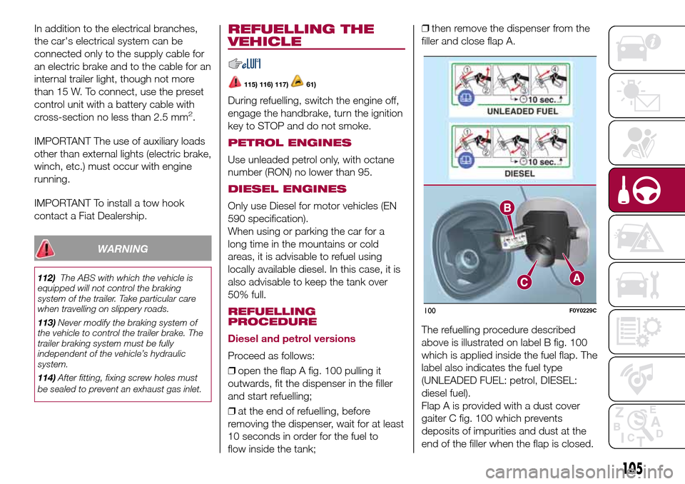
❒open the flap A fig. 100 pulling it
outwards, fit the dispenser in the filler
and start refuelling;
❒at the end of refuelling, before
removing the dispenser, wait for at least
10 seconds in order for the fuel to
flow inside the tank;❒then remove the dispenser from the
filler and close flap A.
The refuelling procedure described
above is illustrated on label B fig. 100
which is applied inside the fuel flap. The
label also indicates the fuel type
(UNLEADED FUEL: petrol, DIESEL:
diesel fuel).
Flap A is provided with a dust cover
gaiter C fig. 100 which prevents
deposits of impurities and dust at the
end of the filler when the flap is closed.
100F0Y0229C
105
Page 110 of 240
IN AN EMERGENCY
A punctured tyre or a burnt-out bulb?
At times, a problem may interfere
with our journey.
The pages on emergencies can help
you to deal with critical situations
independently and with calm.
In an emergency we recommend that
you call the freephone number found in
the Warranty Booklet.
It is also possible to call the national or
international universal freephone
number to search for the nearest
Dealership.HAZARD WARNING LIGHTS...........109
CHANGING A WHEEL ....................109
"FIX&GO AUTOMATIC" KIT .............113
REPLACING A BULB ......................115
REPLACING FUSES........................122
JUMP STARTING ............................128
FUEL CUT-OFF SYSTEM ................129
TOWING THE VEHICLE ..................130
108
IN AN EMERGENCY
Page 111 of 240
HAZARD WARNING
LIGHTS
CONTROL
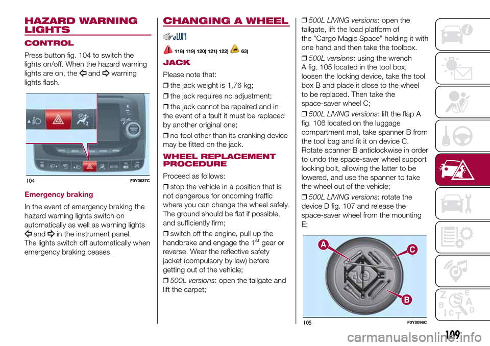
Press button fig. 104 to switch the
lights on/off. When the hazard warning
lights are on, the
andwarning
lights flash.
Emergency braking
In the event of emergency braking the
hazard warning lights switch on
automatically as well as warning lights
andin the instrument panel.
The lights switch off automatically when
emergency braking ceases.
CHANGING A WHEEL
118) 119) 120) 121) 122)63)
JACK
Please note that:
❒the jack weight is 1,76 kg;
❒the jack requires no adjustment;
❒the jack cannot be repaired and in
the event of a fault it must be replaced
by another original one;
❒no tool other than its cranking device
may be fitted on the jack.
WHEEL REPLACEMENT
PROCEDURE
Proceed as follows:
❒stop the vehicle in a position that is
not dangerous for oncoming traffic
where you can change the wheel safely.
The ground should be flat if possible,
and sufficiently firm;
❒switch off the engine, pull up the
handbrake and engage the 1
stgear or
reverse. Wear the reflective safety
jacket (compulsory by law) before
getting out of the vehicle;
❒500L versions: open the tailgate and
lift the carpet;❒500L LIVING versions: open the
tailgate, lift the load platform of
the "Cargo Magic Space" holding it with
one hand and then take the toolbox.
❒500L versions: using the wrench
A fig. 105 located in the tool box,
loosen the locking device, take the tool
box B and place it close to the wheel
to be replaced. Then take the
space-saver wheel C;
❒500L LIVING versions: lift the flap A
fig. 106 located on the luggage
compartment mat, take spanner B from
the tool bag and fit it on device C.
Rotate spanner B anticlockwise in order
to undo the space-saver wheel support
locking bolt, allowing the latter to be
lowered, and use the spanner to take
the wheel out of the vehicle;
❒500L LIVING versions: rotate the
device D fig. 107 and release the
space-saver wheel from the mounting
E;
104F0Y0037C
105F0Y0096C
109
Page 114 of 240
❒fit the standard wheel inserting the 5
stud bolts into the holes;
❒press-fit the wheel cap, aligning the
special splining (on the cap) with the
inflation valve;
❒using the spanner provided, tighten
the fixing stud bolts;
❒lower the vehicle and remove the
jack;
❒using the spanner provided, fully
tighten the stud bolts in the sequence
shown previously.
Versions with alloy wheels
❒insert the wheel on the hub and using
the spanner provided tighten the stud
bolts;
❒lower the vehicle and remove the
jack;
❒using the spanner provided, fully
tighten the 5 stud bolts in the sequence
shown;❒reinstall the hub cap, taking care to
position the three plastic pins in the
dedicated seats on the wheel. Slightly
press the cap to prevent any damage
to the plastic pins.
IMPORTANT If it is not fitted properly,
the hub cap may detach itself when the
car is running.
After tyre replacement
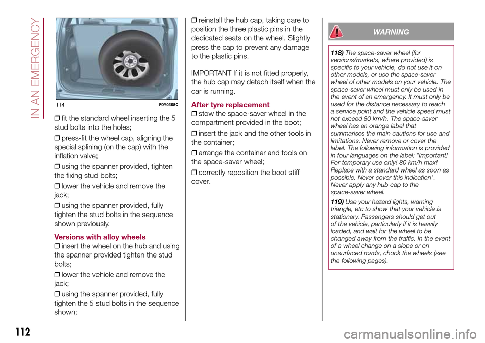
❒stow the space-saver wheel in the
compartment provided in the boot;
❒insert the jack and the other tools in
the container;
❒arrange the container and tools on
the space-saver wheel;
❒correctly reposition the boot stiff
cover.
WARNING
118)The space-saver wheel (for
versions/markets, where provided) is
specific to your vehicle, do not use it on
other models, or use the space-saver
wheel of other models on your vehicle. The
space-saver wheel must only be used in
the event of an emergency. It must only be
used for the distance necessary to reach
a service point and the vehicle speed must
not exceed 80 km/h. The space-saver
wheel has an orange label that
summarises the main cautions for use and
limitations. Never remove or cover the
label. The following information is provided
in four languages on the label: "Important!
For temporary use only! 80 km/h max!
Replace with a standard wheel as soon as
possible. Never cover this indication".
Never apply any hub cap to the
space-saver wheel.
119)Use your hazard lights, warning
triangle, etc to show that your vehicle is
stationary. Passengers should get out
of the vehicle, particularly if it is heavily
loaded, and wait for the wheel to be
changed away from the traffic. In the event
of a wheel change on a slope or on
unsurfaced roads, chock the wheels (see
the following pages).
114F0Y0368C
112
IN AN EMERGENCY