2017 FIAT 124 SPIDER lights
[x] Cancel search: lightsPage 198 of 300
REPLACING FUSES
General Information
Warning!
When replacing a blown fuse, always
use an appropriate replacement fuse with
the same amp rating as the original fuse.
Never replace a fuse with another fuse of
higher amp rating. Never replace a blown
fuse with metal wires or any other material.
Failure to use proper fuses may result in
serious personal injury, fire and/or property
damage.
Before replacing a fuse, make sure that
the ignition is off and that all the other
services are switched off and/or
disengaged.
If the replaced fuse blows again, contact
an authorized dealer.
If a general protection fuse for safety
systems (air bag system, braking system),
power unit systems (engine system,
gearbox system) or steering system blows,
contact an authorized dealer.
Your vehicle's electrical system is
protected by fuses.
If any lights, accessories, or controls do
not work, inspect the appropriate circuit
protector. If a fuse has blown, the inside
element will be melted. If the same fuse
blows again, go to an Authorized Dealer
as soon as possible.
Fuse location
Fuses are grouped together in two fuse
boxes located in the interior on the left
side of the vehicle and under the hood.
Interior Fuses
If the electrical system does not work,
first inspect the fuses on the vehicle's
left side.
Proceed as follows:
1. Make sure the ignition is placed in
the OFF mode, and other switches are
turned off.
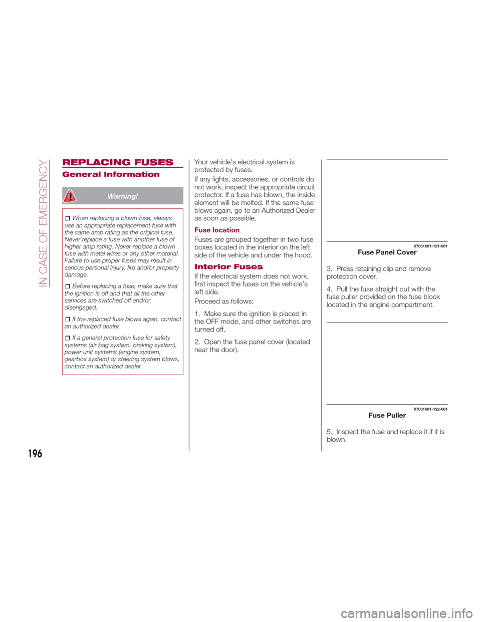
2. Open the fuse panel cover (located
near the door). 3. Press retaining clip and remove
protection cover.
4. Pull the fuse straight out with the
fuse puller provided on the fuse block
located in the engine compartment.
5. Inspect the fuse and replace it if it is
blown.
07031601-121-001Fuse Panel Cover
07031601-122-001Fuse Puller
196
IN CASE OF EMERGENCY
Page 199 of 300
6. Insert a new fuse of the same
amperage rating, and make sure it fits
tightly. If it does not fit tightly, contact an
Authorized Dealer. If you have no spare
fuses, borrow one of the same rating
from a circuit not essential to vehicle
operation, such as the audio or outlet
circuit.
7. Reinstall the cover and make sure
that it is securely installed.
Note:Always replace a fuse with a
genuine FCA fuse or equivalent of the
same rating. Otherwise you may
damage the electric system.
Underhood Fuses
If the headlights or other electrical
components do not work and the fuses
in the cabin are normal, inspect the fuse
block in the engine compartment. If a
fuse is blown, it must be replaced.
Make sure the ignition is placed in the
OFF mode, and other switches are
turned off and remove the fuse block
cover. If the lock is forcefully opened,
the fuse block cover may come in
contact with the frame when it is
removed and become scratched.
When removing the cover, remove it
slowly according to the following
procedure:
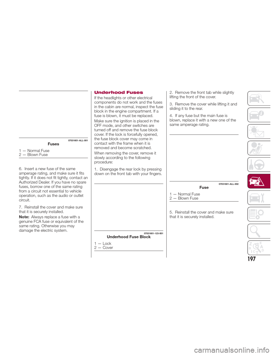
1. Disengage the rear lock by pressing
down on the front tab with your fingers. 2. Remove the front tab while slightly
lifting the front of the cover.
3. Remove the cover while lifting it and
sliding it to the rear.
4. If any fuse but the main fuse is
blown, replace it with a new one of the
same amperage rating.
5. Reinstall the cover and make sure
that it is securely installed.
07031601-ALL-001Fuses
1 — Normal Fuse
2 — Blown Fuse
07031601-123-001Underhood Fuse Block
1 — Lock
2 — Cover
07031601-ALL-002Fuse
1 — Normal Fuse
2 — Blown Fuse
197
Page 202 of 300
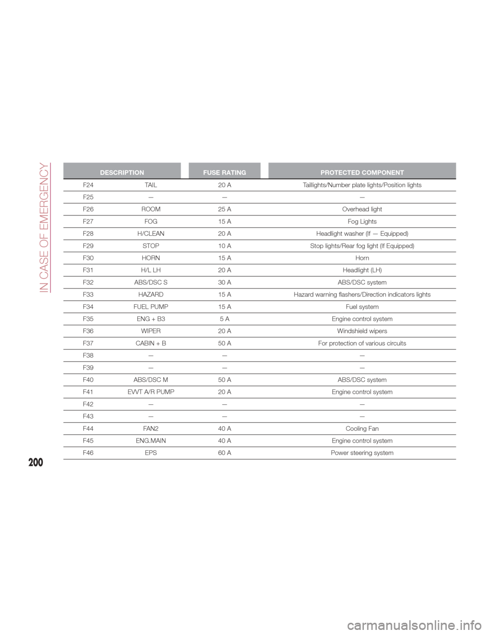
DESCRIPTIONFUSE RATING PROTECTED COMPONENT
F24 TAIL 20 A Taillights/Number plate lights/Position lights
F25
— — —
F26 ROOM 25 A Overhead light
F27 FOG 15 A Fog Lights
F28 H/CLEAN 20 A Headlight washer (If — Equipped)
F29 STOP 10 A Stop lights/Rear fog light (If Equipped)
F30 HORN 15 A Horn
F31 H/L LH 20 A Headlight (LH)
F32 ABS/DSC S 30 A ABS/DSC system
F33 HAZARD 15 AHazard warning flashers/Direction indicators lights
F34 FUEL PUMP 15 A Fuel system
F35 ENG + B3 5 A Engine control system
F36 WIPER 20 A Windshield wipers
F37 CABIN + B 50 A For protection of various circuits
F38 — — —
F39 — — —
F40 ABS/DSC M 50 A ABS/DSC system
F41 EVVT A/R PUMP 20 A Engine control system
F42 — — —
F43 — — —
F44 FAN2 40 A Cooling Fan
F45 ENG.MAIN 40 A Engine control system
F46 EPS 60 A Power steering system
200
IN CASE OF EMERGENCY
Page 207 of 300
To Secure The Jack
Proceed as follows:
1. Insert the wing bolt into the jack with
the jack screw pointing back, and turn
the wing bolt clockwise to temporarily
tighten it.
2. Turn the jack screw clockwise.
3. Turn the wing bolt completely to
secure the jack.
4. Insert the cover tabs and install the
cover.
Warning!
A loose tire or jack thrown forward in a
collision or hard stop could endanger the
occupants of the vehicle. Always stow the
jack parts and the spare tire in the places
provided. Have the deflated (flat) tire
repaired or replaced immediately.
Maintenance
Always keep the jack clean.
Make sure the moving parts are kept
free from dirt or rust.
Make sure the screw thread is
adequately lubricated. Conditions Of Non-Use
Temperatures below -40°F (−40°C)
On sandy or muddy ground
On uneven ground
On steep roads
In extreme weather conditions
In direct contact with the engine or
for repairs under the vehicle
On boats
Changing Procedure
Note: Make sure the jack is well
lubricated before using it.
Warning!
Do not attempt to change a tire on the side
of the vehicle close to moving traffic, pull
far enough off the road to avoid being hit
when operating the jack or changing the
wheel.
Proceed as follows:
1. Stop the vehicle in a position that
does not cause any danger to traffic
and lets you change the tire in safety, as
far as possible from the edge of the
driving lane. The ground must be flat
and sufficiently compact. 2. Turn on the hazard warning lights
and engage the parking brake.
3. For vehicles with automatic
transmission, place the gear selector in
Park (P). For vehicles with manual
transmission, place gear selector in
Reverse (R) and turn off the engine.
4. Stop the engine. The motor must be
kept off as long as the vehicle is lifted
off the ground.
5. Remove the jack and tools.
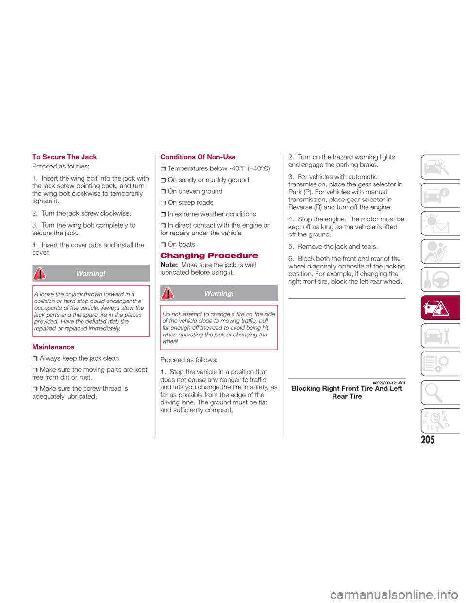
6. Block both the front and rear of the
wheel diagonally opposite of the jacking
position. For example, if changing the
right front tire, block the left rear wheel.
08020300-121-001Blocking Right Front Tire And Left
Rear Tire
205
Page 213 of 300
U.S.A. And CANADA Markets:
Proceed as follows:
1. Pull over to a safe location and turn
on the vehicle’s hazard warning lights.
2. Verify that the valve stem (on the
wheel with the deflated tire) is in a
position that is near to the ground. This
will allow the tire service kit hoses to
reach the valve stem and keep the tire
service kit flat on the ground. This will
provide the best positioning of the kit
when injecting the sealant into the
deflated tire and running the air pump.
Move the vehicle as necessary to place
the valve stem in this position before
proceeding.
3. Shift the gear selector to Reverse (R)
for a manual transmission, and shift the
gear selector to Park (P) for an
automatic transmission.
4. Apply the parking brake with the
brake pedal depressed and turn off the
engine.
5. Unload passengers and cargo and
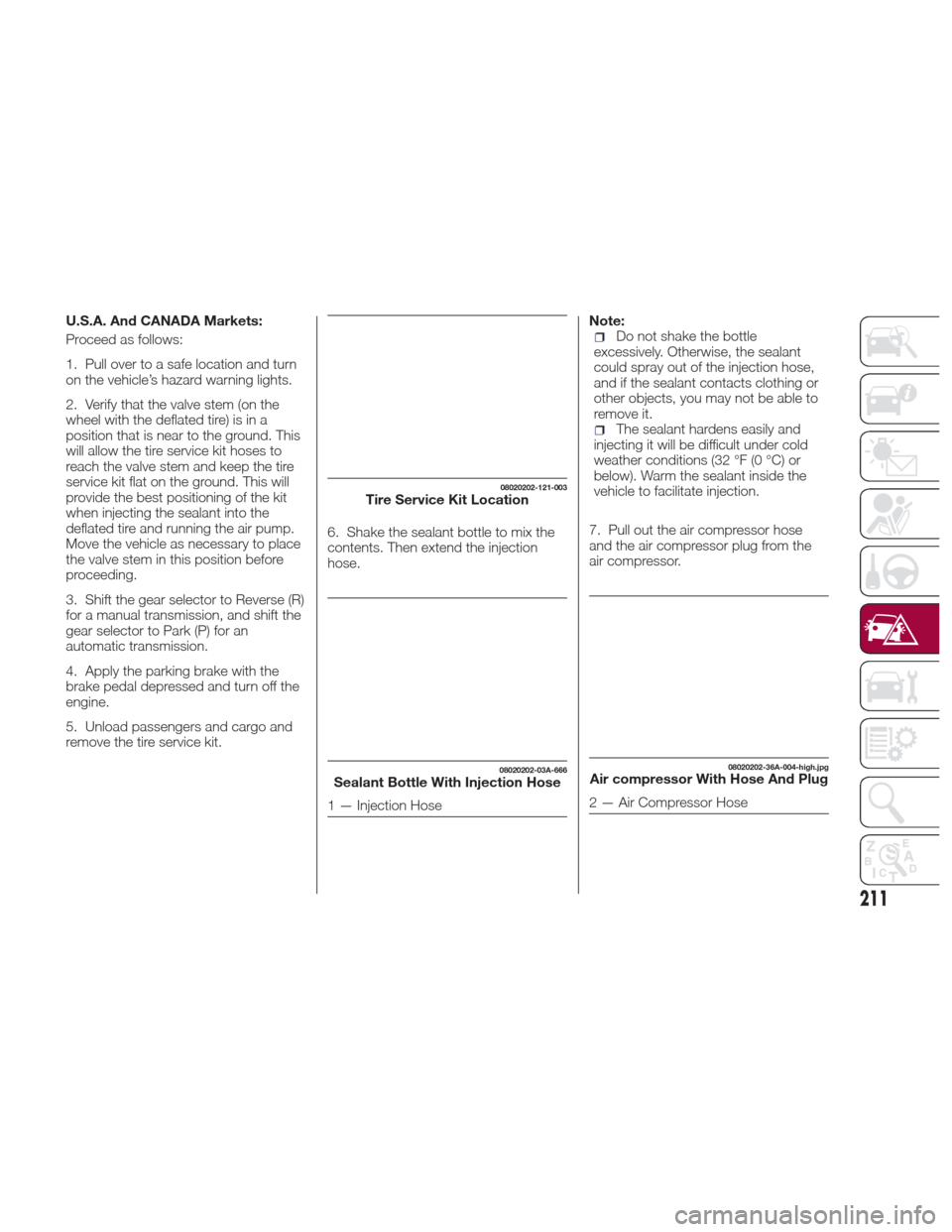
remove the tire service kit.6. Shake the sealant bottle to mix the
contents. Then extend the injection
hose.Note:Do not shake the bottle
excessively. Otherwise, the sealant
could spray out of the injection hose,
and if the sealant contacts clothing or
other objects, you may not be able to
remove it.
The sealant hardens easily and
injecting it will be difficult under cold
weather conditions (32 °F (0 °C) or
below). Warm the sealant inside the
vehicle to facilitate injection.
7. Pull out the air compressor hose
and the air compressor plug from the
air compressor.
08020202-121-003Tire Service Kit Location
08020202-03A-666Sealant Bottle With Injection Hose
1 — Injection Hose
08020202-36A-004-high.jpgAir compressor With Hose And Plug
2 — Air Compressor Hose
211
Page 215 of 300
Warning!
Never use the air compressor above
43.5 psi (3 Bar). Using the air compressor
at an inflation pressure above 3 Bar
(43.5 psi) continuously is dangerous. If the
air compressor overheats, hot air will be
exhausted and you could get burned.
Caution!
If the tire inflation pressure does not
increase, repair of the tire is not possible. If
the tire does not reach the specified tire
inflation pressure within 10 minutes, it may
have received extensive damage. In this
case, the repair using the tire service kit
was not successful.
Do not operate the air compressor for a
continuous 10 minutes or longer because
using it for long periods could cause a
malfunction.
13. Adhere the speed restriction sticker
to an area where it can be viewed easily
by the driver.
Warning!
Do not adhere the speed restriction sticker
to the padded area on the steering wheel.
Adhering the speed restriction sticker to
the padded area on the steering wheel is
dangerous because the air bag may not
operate (deploy) normally resulting in
serious injury. In addition, do not adhere
the sticker to areas where warning lights or
the speedometer cannot be viewed.
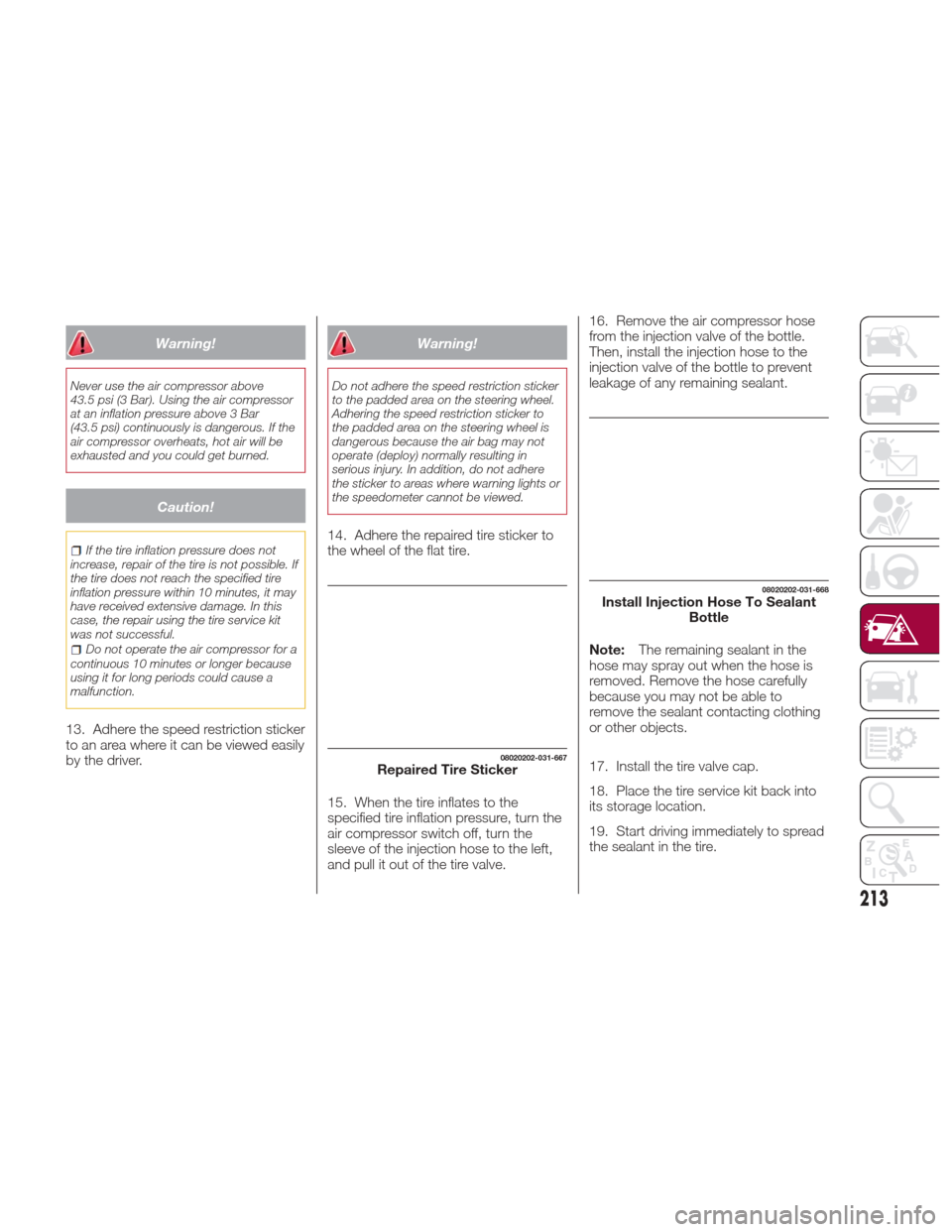
14. Adhere the repaired tire sticker to
the wheel of the flat tire.
15. When the tire inflates to the
specified tire inflation pressure, turn the
air compressor switch off, turn the
sleeve of the injection hose to the left,
and pull it out of the tire valve. 16. Remove the air compressor hose
from the injection valve of the bottle.
Then, install the injection hose to the
injection valve of the bottle to prevent
leakage of any remaining sealant.
Note:
The remaining sealant in the
hose may spray out when the hose is
removed. Remove the hose carefully
because you may not be able to
remove the sealant contacting clothing
or other objects.
17. Install the tire valve cap.
18. Place the tire service kit back into
its storage location.
19. Start driving immediately to spread
the sealant in the tire.
08020202-031-667Repaired Tire Sticker
08020202-031-668Install Injection Hose To Sealant Bottle
213
Page 217 of 300
Mexico Market
Proceed as follows:
1. Pull over to a safe location and turn
on the vehicle’s hazard warning lights.
2. Verify that the valve stem (on the
wheel with the deflated tire) is in a
position that is near to the ground. This
will allow the tire service kit hoses to
reach the valve stem and keep the tire
service kit flat on the ground. This will
provide the best positioning of the kit
when injecting the sealant into the
deflated tire and running the air pump.
Move the vehicle as necessary to place
the valve stem in this position before
proceeding.
3. Shift the gear selector to Reverse (R)
for a manual transmission, and shift the
gear selector to Park (P) for an
automatic transmission.
4. Apply the parking brake with the
brake pedal depressed and turn off the
engine.
5. Unload passengers and cargo and
remove the tire service kit.6. Shake the tire sealant well. If the
bottle is shaken after the injection hose
is screwed on, tire sealant could spray
out from the injection hose. Tire sealant
contacting clothing or other objects
may be impossible to remove. Shake
the bottle before screwing on the
injection hose.
Note:
Do not shake the bottle
excessively. Otherwise, the sealant
could spray out of the injection hose,
and if the sealant contacts clothing or
other objects, you may not be able to
remove it.
The sealant hardens easily and
injecting it will be difficult under cold
weather conditions (32 °F (0 °C) or
below). Warm the sealant inside the
vehicle to facilitate injection.
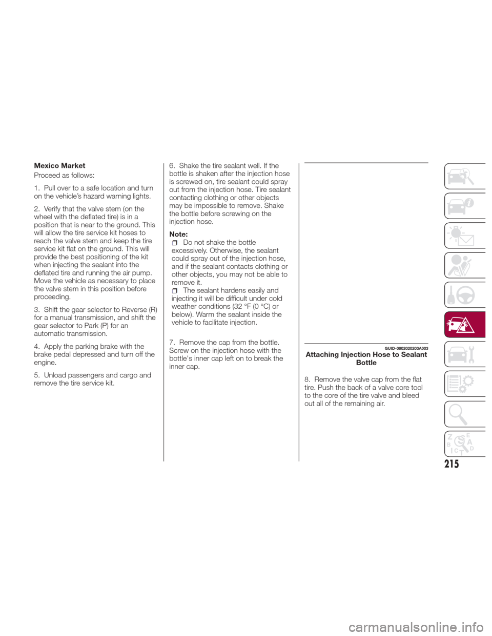
7. Remove the cap from the bottle.
Screw on the injection hose with the
bottle's inner cap left on to break the
inner cap. 8. Remove the valve cap from the flat
tire. Push the back of a valve core tool
to the core of the tire valve and bleed
out all of the remaining air.
GUID-0802020203A003Attaching Injection Hose to SealantBottle
215
Page 219 of 300
13. Reinsert the valve core into the
valve and turn it clockwise to install.
Note:
The tire sealant cannot be reused.
If the tire sealant kit has been used, or
is expired, purchase new one at an
Authorized Dealer.
Do not throw away the empty tire
sealant bottle after use. Return the
empty tire sealant bottle to an
Authorized Dealer when replacing the
tire. The empty tire sealant bottle will
need to be used to extract and dispose
of the used sealant from the tire.
14. Install the injection hose to the tab
of the bottle to prevent leakage of any
remaining sealant.
15. Adhere the speed restriction sticker
to an area where it can be viewed easily
by the driver.
Warning!
Do not adhere the speed restriction sticker
to the padded area on the steering wheel.
Adhering the speed restriction sticker to
the padded area on the steering wheel is
dangerous because the air bag may not
operate (deploy) normally resulting in
serious injury. In addition, do not adhere
the sticker to areas where warning lights or
the speedometer cannot be viewed.
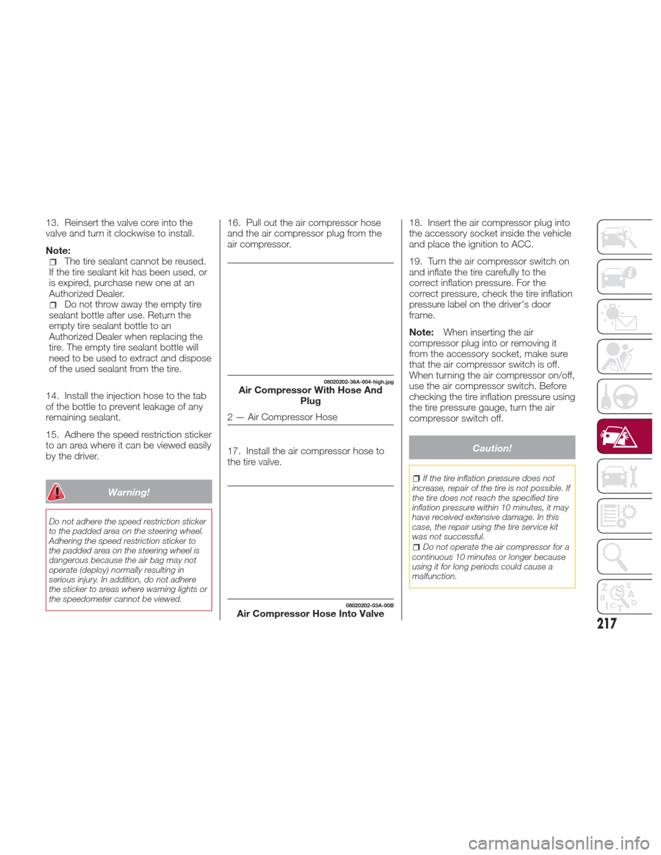
16. Pull out the air compressor hose
and the air compressor plug from the
air compressor.
17. Install the air compressor hose to
the tire valve. 18. Insert the air compressor plug into
the accessory socket inside the vehicle
and place the ignition to ACC.
19. Turn the air compressor switch on
and inflate the tire carefully to the
correct inflation pressure. For the
correct pressure, check the tire inflation
pressure label on the driver's door
frame.
Note:
When inserting the air
compressor plug into or removing it
from the accessory socket, make sure
that the air compressor switch is off.
When turning the air compressor on/off,
use the air compressor switch. Before
checking the tire inflation pressure using
the tire pressure gauge, turn the air
compressor switch off.
Caution!
If the tire inflation pressure does not
increase, repair of the tire is not possible. If
the tire does not reach the specified tire
inflation pressure within 10 minutes, it may
have received extensive damage. In this
case, the repair using the tire service kit
was not successful.
Do not operate the air compressor for a
continuous 10 minutes or longer because
using it for long periods could cause a
malfunction.
08020202-36A-004-high.jpgAir Compressor With Hose And Plug
2 — Air Compressor Hose
08020202-03A-00BAir Compressor Hose Into Valve
217