2017 FIAT 124 SPIDER radio
[x] Cancel search: radioPage 125 of 300

Note:
The tire pressure sensor ID signal
code must be registered when a new
tire pressure sensor is purchased. For
purchase of a tire pressure sensor and
registration of the tire pressure sensor
ID signal code, consult your Authorized
Dealer.
When reinstalling a previously
removed tire pressure sensor to a
wheel, replace the grommet (seal
between valve body/sensor and wheel)
for the tire pressure sensor.
Caution!
The TPMS has been optimized for the
original equipment tires and wheels.
TPMS pressures and warning have been
established for the tire size equipped on
your vehicle. Undesirable system operation
or sensor damage may result when using
replacement equipment that is not of the
same size, type, and/or style. Aftermarket
wheels can cause sensor damage.
Using aftermarket tire sealants may
cause the Tire Pressure Monitoring System
(TPMS) sensor to become inoperable.
After using an aftermarket tire sealant it is
recommended that you take your vehicle to
an Authorized Dealership to have your
sensor function checked.
After inspecting or adjusting the tire
pressure always reinstall the valve stem
cap. This will prevent moisture and dirt
from entering the valve stem, which could
damage the TPMS sensor.
The following regulatory statement
applies to all radio frequency (RF)
devices equipped in this vehicle:
This device complies with Part 15 of the
FCC Rules and with Industry Canada
license-exempt RSS standard(s).
Operation is subject to the following
two conditions:
(1) This device may not cause harmful
interference, and
(2) This device must accept any
interference received, including
interference that may cause undesired
operation.
Note:
Changes or modifications not expressly
approved by the party responsible for
compliance could void the user’s
authority to operate the equipment.
OCCUPANT
RESTRAINT
SYSTEMS
The most important safety equipment
of the vehicle comprise the following
protection systems:
Seat Belts
SBA (Seat Belt Alert) System
Head Restraints
Child Restraint Systems
Front Air Bags And Side Air Bags
Read the information given in the
following pages with the utmost care.
It is of fundamental importance that the
protection systems are used in the
correct way to guarantee the maximum
possible safety level for the driver and
the passengers.
123
Page 164 of 300

RADAR SENSORS —
IF EQUIPPED
Rear Radar Sensors
The following systems use the rear
radar sensors:
Blind Spot Monitoring System (BSM)
Rear Cross Traffic Alert (RCTA)
The radar sensors function by detecting
the radio waves reflected off of a vehicle
approaching from the rear or an
obstruction sent from the radar sensor.
The radar sensors are installed inside
the rear bumper, one each on the left
and right sides.
Always keep the surface of the rear
bumper near the radar sensors clean so
that the radar sensors operate normally.
Also, do not apply items such as
stickers.
Caution!
If the rear bumper receives a severe
impact, the system may no longer operate
normally. Stop the system immediately and
contact an Authorized Dealer.
The detection ability of the radar
sensors has limitations. In the following
cases, the detection ability may lower
and the system may not operate
normally:
The rear bumper near the radar
sensors has become deformed.
Snow, ice or mud adheres to the
radar sensors on the rear bumper.
Under bad weather conditions such
as rain, snow and fog.
Note: Under the following conditions,
the radar sensors cannot detect target
objects or it may be difficult to detect
them:
Stationary objects on a road or a
road side such as small, two-wheeled
vehicles, bicycles, pedestrians,
animals, and shopping carts.
Vehicle shapes which do not reflect
radar waves well such as empty trailers
with a low vehicle height and sports
cars. Vehicles are shipped with the direction
of the radar sensors adjusted for each
vehicle to a loaded vehicle condition so
that the radar sensors detect
approaching vehicles correctly. If the
direction of the radar sensors has
changed, contact an Authorized Dealer.
The radar sensors are regulated by the
relevant radio wave laws of the country
in which the vehicle is driven. If the
vehicle is driven abroad, authorization
from the country in which the vehicle is
driven may be required.
Note:
For repairs or replacement of the
radar sensors, or bumper repairs,
paintwork, and replacement near the
radar sensors, consult an Authorized
Dealer.
Turn off the system while pulling a
trailer or while an accessory such as a
bicycle carrier is installed to the rear of
the vehicle. Otherwise, the radio waves
emitted by the radar will be blocked
causing the system to not operate
normally.
GUID-07080915112112Radar Sensor Locations
162
STARTING AND OPERATING
Page 166 of 300

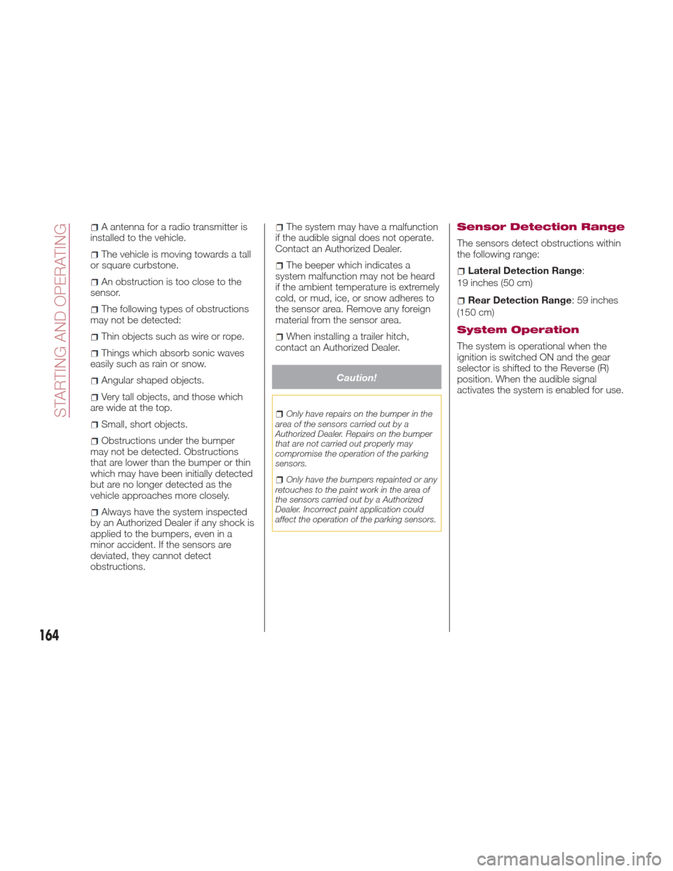
A antenna for a radio transmitter is
installed to the vehicle.
The vehicle is moving towards a tall
or square curbstone.
An obstruction is too close to the
sensor.
The following types of obstructions
may not be detected:
Thin objects such as wire or rope.
Things which absorb sonic waves
easily such as rain or snow.
Angular shaped objects.
Very tall objects, and those which
arewideatthetop.
Small, short objects.
Obstructions under the bumper
may not be detected. Obstructions
that are lower than the bumper or thin
which may have been initially detected
but are no longer detected as the
vehicle approaches more closely.
Always have the system inspected
by an Authorized Dealer if any shock is
applied to the bumpers, even in a
minor accident. If the sensors are
deviated, they cannot detect
obstructions.
The system may have a malfunction
if the audible signal does not operate.
Contact an Authorized Dealer.
The beeper which indicates a
system malfunction may not be heard
if the ambient temperature is extremely
cold, or mud, ice, or snow adheres to
the sensor area. Remove any foreign
material from the sensor area.
When installing a trailer hitch,
contact an Authorized Dealer.
Caution!
Only have repairs on the bumper in the
area of the sensors carried out by a
Authorized Dealer. Repairs on the bumper
that are not carried out properly may
compromise the operation of the parking
sensors.
Only have the bumpers repainted or any
retouches to the paint work in the area of
the sensors carried out by a Authorized
Dealer. Incorrect paint application could
affect the operation of the parking sensors.
Sensor Detection Range
The sensors detect obstructions within
the following range:
Lateral Detection Range :
19 inches (50 cm)
Rear Detection Range :59inches
(150 cm)
System Operation
The system is operational when the
ignition is switched ON and the gear
selector is shifted to the Reverse (R)
position. When the audible signal
activates the system is enabled for use.
164
STARTING AND OPERATING
Page 201 of 300

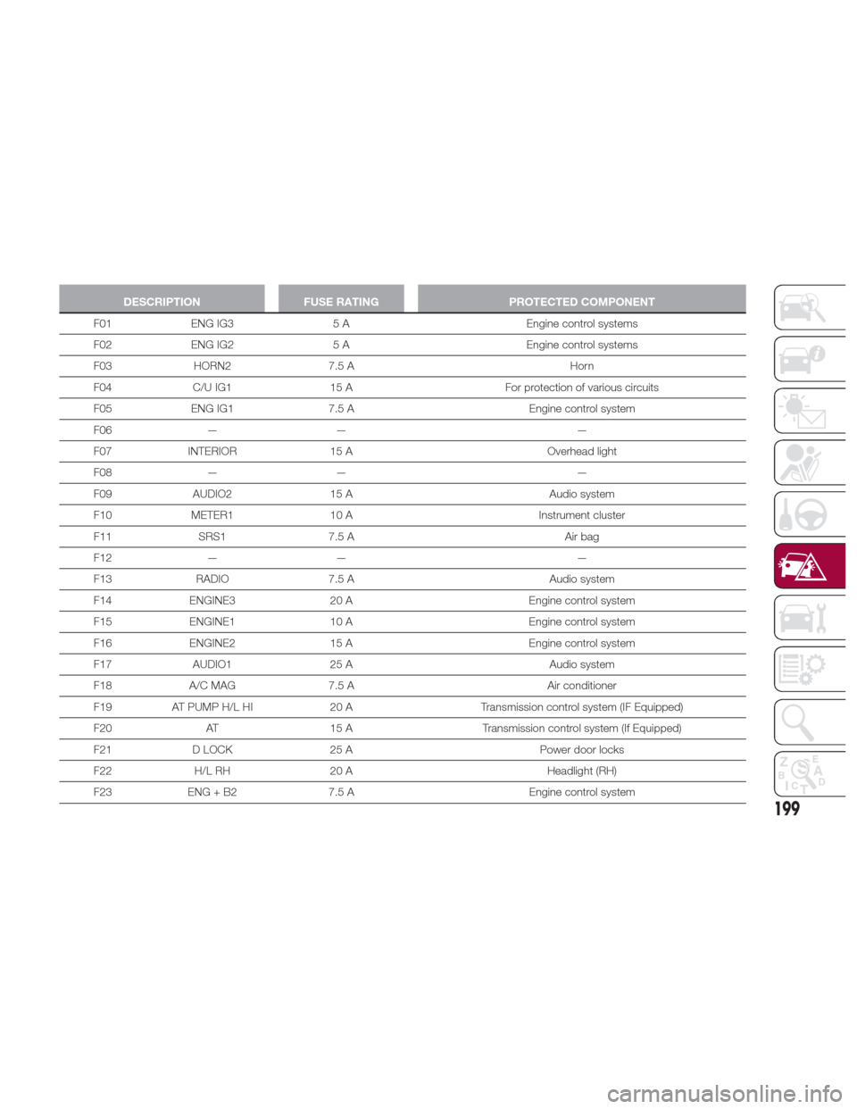
DESCRIPTIONFUSE RATING PROTECTED COMPONENT
F01 ENG IG3 5 A Engine control systems
F02
ENG IG2 5 A Engine control systems
F03 HORN2 7.5 A Horn
F04 C/U IG1 15 A For protection of various circuits
F05 ENG IG1 7.5 A Engine control system
F06 — — —
F07 INTERIOR 15 A Overhead light
F08 — — —
F09 AUDIO2 15 A Audio system
F10 METER1 10 A Instrument cluster
F11 SRS1 7.5 A Air bag
F12 — — —
F13 RADIO 7.5 A Audio system
F14 ENGINE3 20 A Engine control system
F15 ENGINE1 10 A Engine control system
F16 ENGINE2 15 A Engine control system
F17 AUDIO1 25 A Audio system
F18 A/C MAG 7.5 A Air conditioner
F19 AT PUMP H/L HI 20 ATransmission control system (IF Equipped)
F20 AT 15 A Transmission control system (If Equipped)
F21 D LOCK 25 A Power door locks
F22 H/L RH 20 A Headlight (RH)
F23 ENG + B2 7.5 A Engine control system
199
Page 280 of 300

ELECTROMAGNETIC COMPATIBILITY
Electromagnetic Compatibility
Your vehicle has been tested and certified to the UNECE 10 regulation (United Nations Economic Commission for Europe) as
related to electromagnetic compatibility.
Radio Frequency (RF) transmitter equipment (e.g. cellular telephones, amateur radio transmitters, etc.) may only be fitted to
your vehicle if they comply with the parameters shown in the table below.
It is your responsibility to ensure that any equipment you have fitted complies with applicable local legislations. Have any
equipment fitted by properly trained technicians.
Note:
Do not mount any transceiver, microphones, speakers, or any other item in the deployment path of the air bag system.
Do not fasten aerial cable to original vehicle wiring, fuel pipes or brake pipes. Avoid running the aerial cable parallel with the
wire harness to the best extent possible.
Keep the aerial and power cables at least 100 mm from any electronic modules and the air bags.
Avoid using the cigar lighter or accessory socket as a power source for the RF-transmitting equipment.
278
TECHNICAL SPECIFICATIONS
Page 290 of 300

Programming Additional Key
Fobs...................24
Key-In Reminder ..............21
Keyless Entry System...........15
Lane Change And Turn Signals ....41
Lane Change Assist ............41
Lap/Shoulder Belts ........124,126
Leaving Home Light System ......42
Life Of Tires ............... .246
Lights Daytime Running ...........40
Fog ...................41
Hazard Warning Flasher ......185
Passing .................40
Turn Signal ...............41
Loading Vehicle .............177
Tires ................. .241
Locks PowerDoor ........... .26,31
Maintaining the finish.........255
Maintenance Monitor ...........85
Maintenance procedures ........236
Manual Climate Control System ....48
Heating .................50
Manual transmission ..........152
Manual Transmission ..........152
Manual, Service .............284
Methanol ................. .173
Mirrors....................36 Automatic Dimming
.........37
Electric Remote ............38
Exterior Folding ............38
Outside .................36
Rearview ................36
Occupant Restraints ..........123
Onboard Diagnostic System ......77
Operating Precautions ..........77
Outside Rearview Mirrors ........36
Overhead light (bulb replacement) . .195
Overheating, Engine ...........220
Overloading ............... .182
Owner's Manual (Operator Manual) ..........284
Paint damage touch-up ........256
Parking Brake ...............151
Passing Light ................40
Performance ...............277
Periodic checks (scheduled servicing) ............... .226
Personal Settings ............108
Personalization Features ........108
Placard, Tire And Loading Information ...............241
Plastic part maintenance ........259
Power Brakes ................ .150
Door Locks ............26,31
Mirrors .................38 Pregnant Women And Seat Belts . .125
Pretensioners
Seat Belts ..............128
Protection from atmospheric agents (bodywork) ..........253
Radar Sensors.............162
Radial Ply Tires ..............245
Radio Frequency General Information ........20,23
Radio transmitter and mobile phones ...................5
Rear Camera ...............167
Rear lights (light bulbs) .........188
Rear Park Assist System ........163
Rear View ..................10
Rearview Mirrors ..............36
Recommended Tire Inflation Pressure ............... .265
Recorder, Event Data ..........146
Recreational towing ...........178
Reformulated Gasoline .........173
Refueling procedure ...........175
Refueling the vehicle ..........173
Reminder, Seat Belt ...........128
Replacement Tires ............247
Replacing a bulb .............185
Replacing exterior light bulbs .....188
Replacing fuses .............196
Replacing interior light bulbs .....195
Reporting Safety Defects .......283
INDEX
Page 299 of 300

INSTALLATION OF RADIO TRANSMITTING
EQUIPMENT
Special design considerations are incorporated into this
vehicle’s electronic system to provide immunity to radio
frequency signals. Mobile two-way radios and telephone
equipment must be installed properly by trained person-
nel. The following must be observed during installation.
The positive power connection should be made directly
to the battery and fused as close to the battery as possible.
The negative power connection should be made to body
sheet metal adjacent to the negative battery connection.
This connection should not be fused.
Antennas for two-way radios should be mounted on the
roof or the rear area of the vehicle. Care should be used
in mounting antennas with magnet bases. Magnets may
affect the accuracy or operation of the compass on
vehicles so equipped.The antenna cable should be as short as practical and
routed away from the vehicle wiring when possible. Use
only fully shielded coaxial cable.
Carefully match the antenna and cable to the radio to
ensure a low Standing Wave Ratio (SWR).
Mobile radio equipment with output power greater than
normal may require special precautions.
All installations should be checked for possible interfer-
ence between the communications equipment and the
vehicle’s electronic systems.