2017 FIAT 124 SPIDER head light
[x] Cancel search: head lightPage 104 of 300
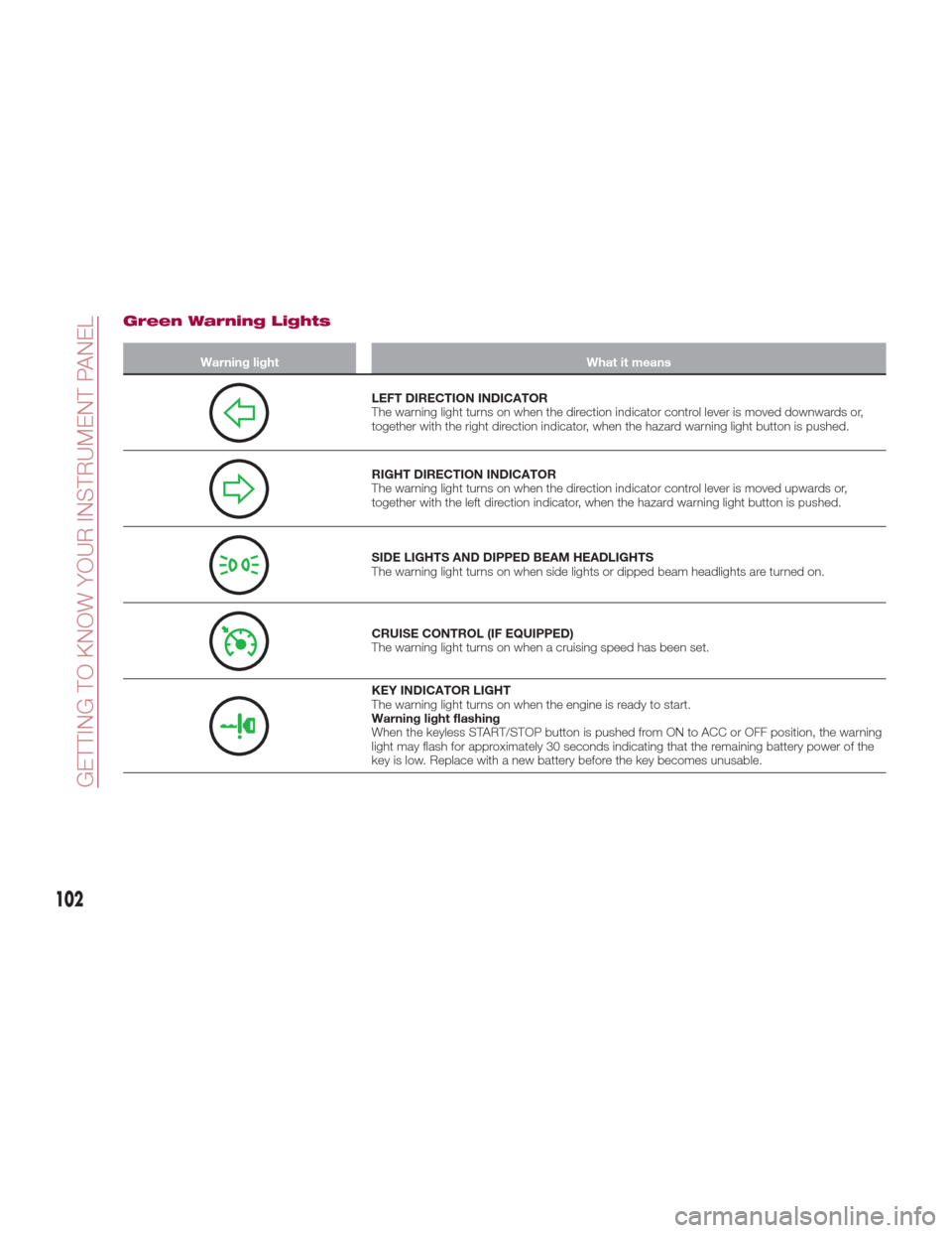
Green Warning Lights
Warning lightWhat it means
LEFT DIRECTION INDICATOR
The warning light turns on when the direction indicator control lever is moved downwards or,
together with the right direction indicator, when the hazard warning light button is pushed.
RIGHT DIRECTION INDICATOR
The warning light turns on when the direction indicator control lever is moved upwards or,
together with the left direction indicator, when the hazard warning light button is pushed.
SIDE LIGHTS AND DIPPED BEAM HEADLIGHTS
The warning light turns on when side lights or dipped beam headlights are turned on.
CRUISE CONTROL (IF EQUIPPED)
The warning light turns on when a cruising speed has been set.
KEY INDICATOR LIGHT
The warning light turns on when the engine is ready to start.
Warning light flashing
When the keyless START/STOP button is pushed from ON to ACC or OFF position, the warning
light may flash for approximately 30 seconds indicating that the remaining battery power of the
key is low. Replace with a new battery before the key becomes unusable.
102
GETTING TO KNOW YOUR INSTRUMENT PANEL
Page 105 of 300

Blue warning light
Warning lightWhat it means
MAIN BEAM HEADLIGHTS
The warning light switches on when the main beam headlights are turned on.
LOW ENGINE COOLANT TEMPERATURE INDICATOR LIGHT
The light illuminates continuously when the engine coolant temperature is low and turns off after
the engine is warm.
If the low engine coolant temperature indicator light remains illuminated after the engine has
been sufficiently warmed up, the temperature sensor could have a malfunction. Contact an
Authorized Dealership.
103
Page 111 of 300
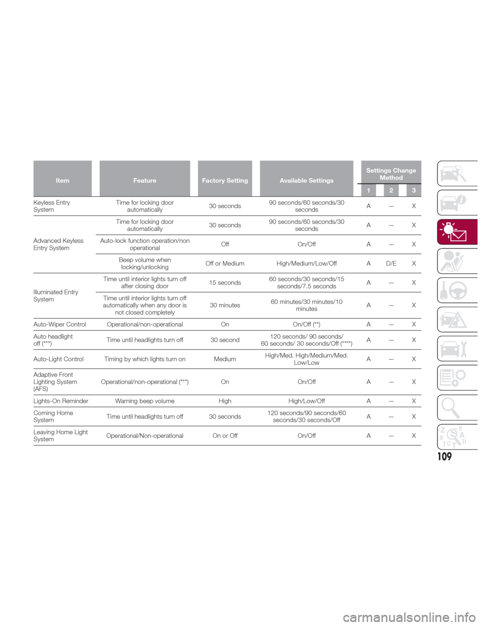
ItemFeatureFactory Setting Available Settings Settings Change
Method
123
Keyless Entry
System T
ime for locking door
automatically 30 seconds90 seconds/60 seconds/30
seconds A—X
Advanced Keyless
Entry System Time for locking door
automatically 30 seconds90 seconds/60 seconds/30
seconds A—X
Auto-lock function operation/non operational Off
On/OffA — X
Beep volume when locking/unlocking Off or Medium
High/Medium/Low/Off A D/E X
Illuminated Entry
System Time until interior lights turn off
after closing door 15 seconds60 seconds/30 seconds/15
seconds/7.5 seconds A—X
Time until interior lights turn off
automatically when any door is not closed completely 30 minutes
60 minutes/30 minutes/10
minutes A—X
Auto-Wiper Control Operational/non-operational OnOn/Off (**) A — X
Auto headlight
off (***) Time until headlights turn off 30 second 120 seconds/ 90 seconds/
60 seconds/ 30 seconds/Off (****) A—X
Auto-Light Control Timing by which lights turn on Medium High/Med. High/Medium/Med.
Low/Low A—X
Adaptive Front
Lighting System
(AFS) Operational/non-operational (***)
OnOn/OffA — X
Lights-On Reminder Warning beep volume HighHigh/Low/Off A — X
Coming Home
System Time until headlights turn off 30 seconds 120 seconds/90 seconds/60
seconds/30 seconds/Off A—X
Leaving Home Light
System Operational/Non-operational On or Off
On/OffA — X
109
Page 118 of 300

beep may not occur or they may be
delayed:
A vehicle makes a lane change from
a driving lane two lanes over to an
adjacent lane.
Driving on steep slopes.
Crossing the summit of a hill or
mountain pass.
The turning radius is small (making a
sharp turn, turning at intersections).
Whenthereisadifferenceinthe
height between your driving lane and
the adjacent lane.
Directly after pushing the BSM
switch and the system becomes
operable.
If the road width is extremely narrow,
vehicles two lanes over may be
detected. The detection area of the
radar sensors (rear) is set according to
the road width of expressways.
The BSM warning lights may turn on in
reaction to stationary objects on the
road or the roadside such as guardrails,
tunnels, sidewalls, and parked vehicles.
A BSM warning lights may flash or the
warning beep may be activated several
times when making a turn at a city
intersection.
Turn off the BSM system while pulling a
trailer or while an accessory such as a
bicycle carrier is installed to the rear of
the vehicle. Otherwise, the radar’s sound system waves will be blocked
causing the system to not operate
normally.
In the following cases, it may be difficult
to view the illumination/flashing of the
BSM warning lights equipped on the
door mirrors:
Snow or ice is adhering to the door
mirrors.
The door glass is fogged or covered
in snow, frost or dirt.
The system switches to the Rear Cross
Traffic Alert function when the gear
selector is shifted to the Reverse (R)
position.
BSM Warning Lights
The BSM warning lights are equipped
on the left and right door mirrors. The warning lights turn on when a
vehicle approaching from the rear in an
adjacent lane is detected.
When the ignition is switched ON, the
malfunction warning light turns on
momentarily and then turns off after a
few seconds.
Forward Driving (BSM System
Operation)
The BSM system detects vehicles
approaching from the rear and turns on
the warning lights equipped on the door
mirrors according to the conditions.
Additionally, while a warning light is
illuminated, if the turn signal lever is
operated to signal a turn in the direction
in which the warning light is illuminated,
the warning light flashes.
Reverse Driving (RCTA System
Operation)
The Rear Cross Traffic Alert (RCTA)
system detects vehicles approaching
from the left and right of your vehicle
and flashes the BSM warning lights.
Function For Cancelling Illumination
Dimmer
When the headlight switch is in the
orposition, the brightness of
the Blind Spot Monitoring (BSM)
warning lights is dimmed. If the Blind
Spot Monitoring (BSM) warning lights
are difficult to see due to glare from
surrounding brightness when traveling
on snow-covered roads or under foggy
conditions, push the dimmer
05280701-12A-001BSM Warning Light
116
SAFETY
Page 134 of 300
Place the child-restraint system on
the seat without putting your weight on
the seat and secure the child-restraint
system with the lap portion of the
lap/shoulder belt. See the
manufacturer's instructions on the
child-restraint system for belt routing
instructions;
To get the retractor into the
automatic locking mode, pull the
shoulder belt portion of the seat belt
until the entire length of the belt is out of
the retractor;
Push the child-restraint system firmly
into the vehicle seat. Be sure the belt
retracts as snugly as possible. A
clicking noise from the retractor will be
heard during retraction if the system is
in automatic locking mode. If the belt
does not lock the seat down tight,
repeat the previous step and also this
one;
Seat your child safely in the
child-restraint system and secure the
child according to the instructions from
the child-restraint system manufacturer; Note:
Inspect this function before
each use of the child restraint system.
You should not be able to pull the
shoulder belt out of the retractor while
the system is in the automatic locking
mode. When you remove the
child-restraint system, be sure the belt
fully retracts to return the system to
emergency locking mode before
occupants use the seat belts.
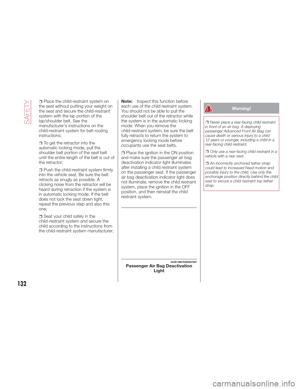
Place the ignition in the ON position
and make sure the passenger air bag
deactivation indicator light illuminates
after installing a child restraint system
on the passenger seat. If the passenger
air bag deactivation indicator light does
not illuminate, remove the child restraint
system, place the ignition in the OFF
position, and then reinstall the child
restraint system.
Warning!
Never place a rear-facing child restraint
in front of an air bag. A deploying
passenger Advanced Front Air Bag can
cause death or serious injury to a child
12 years or younger, including a child in a
rear-facing child restraint.
Only use a rear-facing child restraint in a
vehicle with a rear seat.
An incorrectly anchored tether strap
could lead to increased head motion and
possibly injury to the child. Use only the
anchorage position directly behind the child
seat to secure a child restraint top tether
strap.
GUID-06070400567567Passenger Air Bag Deactivation Light
132
SAFETY
Page 171 of 300
Note:If it is difficult to see the display
under the following conditions, it does
notmeanthatthisisduetoa
malfunction:
In dark areas.
When the temperature around the
lens is particularly high/low.
When the camera is wet from rain
or due to a high atmospheric humidity.
When there is some foreign deposit
around the camera, for example mud.
When the camera lens reflects
sunlight or a headlight beam.
The image on the display may be
delayed if the temperature around the
camera is low.
Caution!
To avoid vehicle damage, ParkView
should only be used as a parking aid. The
ParkView camera is unable to view every
obstacle or object in your drive path.
To avoid vehicle damage, the vehicle
must be driven slowly when using ParkView
to be able to stop in time when an obstacle
is seen. It is recommended that the driver
look frequently over his/her shoulder when
using ParkView.
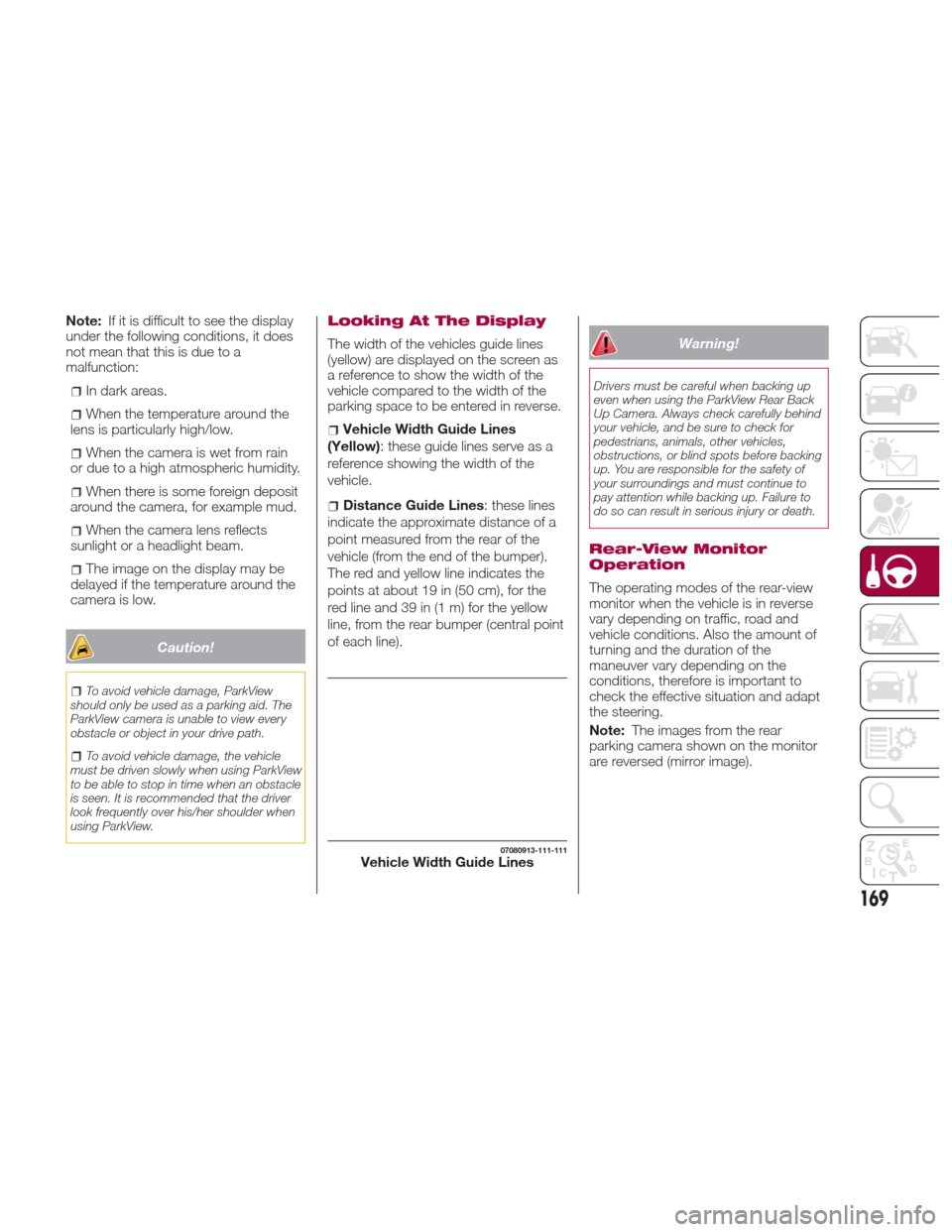
Looking At The Display
The width of the vehicles guide lines
(yellow) are displayed on the screen as
a reference to show the width of the
vehicle compared to the width of the
parking space to be entered in reverse.
Vehicle Width Guide Lines
(Yellow): these guide lines serve as a
reference showing the width of the
vehicle.
Distance Guide Lines : these lines
indicate the approximate distance of a
point measured from the rear of the
vehicle (from the end of the bumper).
The red and yellow line indicates the
pointsatabout19in(50cm),forthe
red line and 39 in (1 m) for the yellow
line, from the rear bumper (central point
of each line).
Warning!
Drivers must be careful when backing up
even when using the ParkView Rear Back
Up Camera. Always check carefully behind
your vehicle, and be sure to check for
pedestrians, animals, other vehicles,
obstructions, or blind spots before backing
up. You are responsible for the safety of
your surroundings and must continue to
pay attention while backing up. Failure to
do so can result in serious injury or death.
Rear-View Monitor
Operation
The operating modes of the rear-view
monitor when the vehicle is in reverse
vary depending on traffic, road and
vehicle conditions. Also the amount of
turning and the duration of the
maneuver vary depending on the
conditions, therefore is important to
check the effective situation and adapt
the steering.
Note: The images from the rear
parking camera shown on the monitor
are reversed (mirror image).
07080913-111-111Vehicle Width Guide Lines
169
Page 181 of 300

Follow the maintenance schedule
and contact your Authorized Dealer.
Use the air conditioner only when
necessary.
Slow down on rough roads.
Keep the tires properly inflated.
Do not carry unnecessary weight.
Do not rest your foot on the brake
pedal while driving.
Keep the wheels in correct
alignment.
Keep windows closed at high
speeds.
Slow down when driving in
crosswinds and headwinds.
Hazardous Driving
When driving on ice or in water, snow,
mud, sand, or similar hazards:
Be cautious and allow extra distance
for braking.
Avoid sudden braking and sudden
maneuvering.
Do not pump the brakes. Continue to
press down on the brake pedal.
If you get stuck, select a lower gear
and accelerate slowly. Do not spin the
rear wheels.
For more traction in starting on
slippery surfaces such as ice or packed
snow, use sand, rock salt, chains,
carpeting, or other nonslip material
under the rear wheels.
Note: Usesnowchainsonlyonthe
rear wheels.
Floor Mat Safety
Information
Always use floor mats designed to fit
the footwell of your vehicle. Use only
floor mats that leave the pedal area
unobstructed and that are firmly
secured so that they cannot slip out of
position and interfere with the pedals or
impair safe operation of your vehicle in
other ways.
Warning!
An improperly attached, damaged, folded,
or stacked floor mat, or damaged floor mat
fasteners may cause your floor mat to
interfere with the accelerator, brake, or
clutch pedals and cause a loss of vehicle
control. To prevent SERIOUS INJURY or
DEATH:
ALWAYS securely attachyour floor
mat using the floor mat fasteners. DO NOT
install your floor mat upside down or turn
your floor mat over. Lightly pull to confirm
mat is secured using the floor mat
fasteners on a regular basis.
ALWAYS REMOVE THE EXISTING
FLOOR MAT FROM THE VEHICLE
before installing any other floor mat.
NEVER install or stack an additional floor
mat on top of an existing floor mat.
ONLY install floor mats designed to fit
your vehicle. NEVER install a floor mat that
cannot be properly attached and secured
to your vehicle. If a floor mat needs to be
replaced, only use a FCA approved floor
mat for the specific make, model, and year
of your vehicle.
04090400-USA-001Floor Mat Retention Post Location
179
Page 188 of 300
Before replacing a bulb check the
contacts for oxidation.
Replace blown bulbs with others of
the same type and power.
After replacing a headlight bulb,
always check its alignment.
To replace the bulb, contact your
Authorized Dealer.
When a light is not working, check
that the corresponding fuse is intact
before replacing the bulb. For the
location of fuses, refer to the section on
“Replacing Fuses” in this chapter.
Caution!
Use the protective cover and carton for the
replacement bulb to dispose of the old bulb
promptly and out of the reach of children.
Note:
When removing the lens or light unit
using a flathead screwdriver, make
sure that the flathead screwdriver does
not contact the interior terminal. If the
flathead screwdriver contacts the
terminal, a short circuit may occur.
When the weather is cold or damp
or after heavy rain or washing, the
surface of headlights or rear lights may
steam up and/or form drops of
condensation on the inside. This is a
natural phenomenon due to the
difference in temperature and humidity
between the inside and the outside of
the glass which does not indicate a
fault and does not compromise the
normal operation of lighting devices.
The mist disappears quickly when the
lights are turned on, starting from the
center of the diffuser, extending
progressively towards the edges.
186
IN CASE OF EMERGENCY