Page 221 of 530

Cargo Area Storage
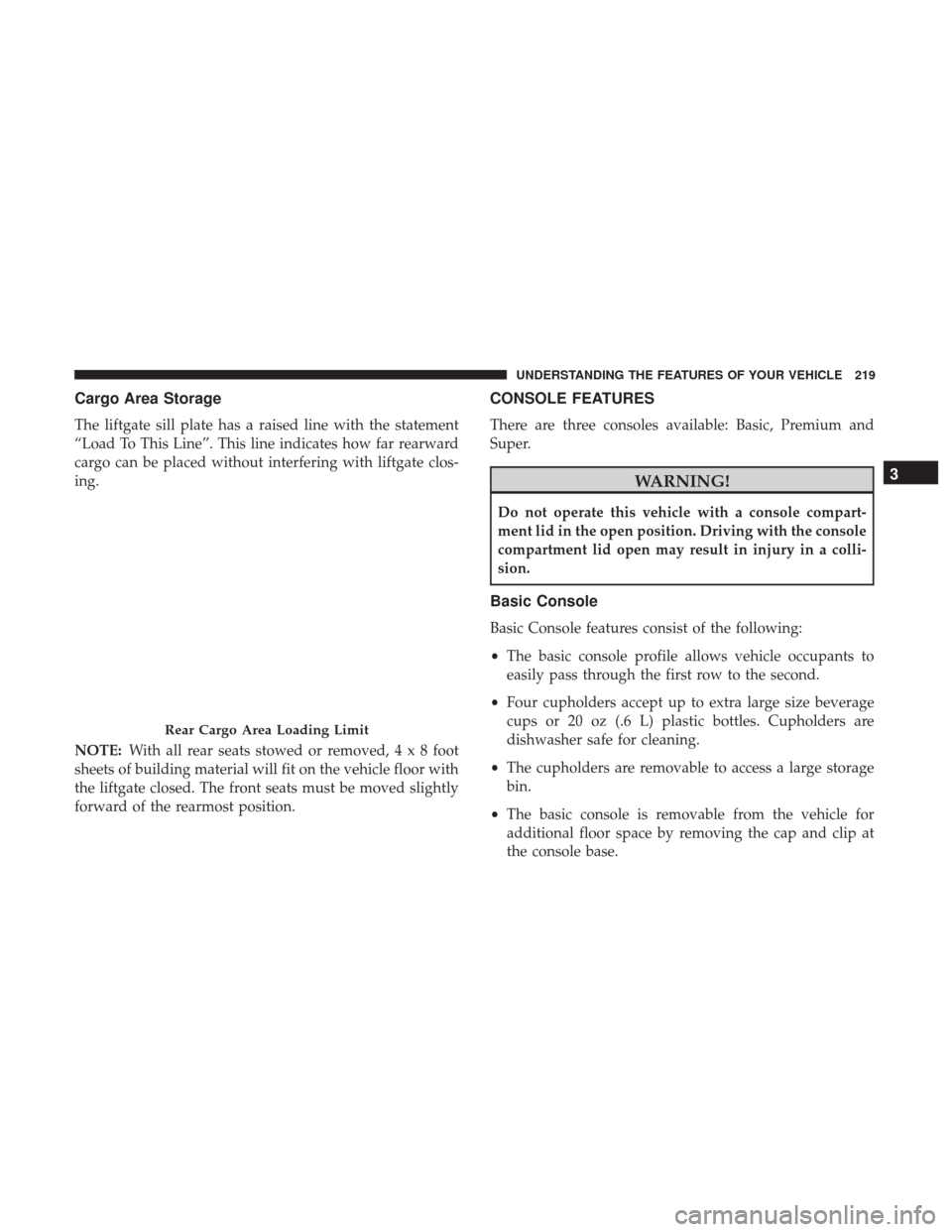
The liftgate sill plate has a raised line with the statement
“Load To This Line”. This line indicates how far rearward
cargo can be placed without interfering with liftgate clos-
ing.
NOTE:With all rear seats stowed or removed,4x8foot
sheets of building material will fit on the vehicle floor with
the liftgate closed. The front seats must be moved slightly
forward of the rearmost position.
CONSOLE FEATURES
There are three consoles available: Basic, Premium and
Super.
WARNING!
Do not operate this vehicle with a console compart-
ment lid in the open position. Driving with the console
compartment lid open may result in injury in a colli-
sion.
Basic Console
Basic Console features consist of the following:
• The basic console profile allows vehicle occupants to
easily pass through the first row to the second.
• Four cupholders accept up to extra large size beverage
cups or 20 oz (.6 L) plastic bottles. Cupholders are
dishwasher safe for cleaning.
• The cupholders are removable to access a large storage
bin.
• The basic console is removable from the vehicle for
additional floor space by removing the cap and clip at
the console base.
Rear Cargo Area Loading Limit
3
UNDERSTANDING THE FEATURES OF YOUR VEHICLE 219
Page 222 of 530

To Remove The Basic Floor Console
1. Remove the front anchor cup plug and clip.
2. Slide the console base forward while lifting slightly toclear the rear load floor hook.
3. Remove the console.
To Reinstall The Basic Floor Console
1. Position the console at a slight angle (front slightly higher than the rear).
2. Slide the console rearward into the floor bracket/hook.
3. Align the console until the front anchor cup plug hole is centered on the winch hole.
4. Reinstall the clip first and then while pushing down- ward on the console with slight pressure, reinstall the
cover plug.
5. Pull up on the console to be sure it is firmly latched.
WARNING!
In an accident, serious injury could result if the remov-
able floor console is not properly installed. Always be
sure the removable floor console is fully latched.
Premium Console — If Equipped
The three-compartment console with sliding storage bin,
sliding upper tray with storage and large console storage
bin offers multiple configurations.
• Four cupholders with dishwasher safe liners for clean-
ing. The cupholders can accept plastic bottles, large cups
or mugs with handles
• Top tray storage
• Upper storage bin can hold nine regular or 18 thin CDs
or other items
• Large console center storage will store headphones for
the available rear DVD entertainment system or other
items
• 12 Volt DC power outlet provides continuous power
inside the console for cell phones or other electronics
• Rear occupant accessible
• Multiple adjustments
• Removable from vehicle for additional floor space
The top and center console sections slide forward and
rearward to provide added user comfort. A one-piece cup
220 UNDERSTANDING THE FEATURES OF YOUR VEHICLE
Page 225 of 530

To Reinstall The Premium Floor Console:
1. Position the console at a slight angle (rear slightly higherthan the front).
2. Slide the console forward into the floor bracket.
3. Rotate the rear of the console down until it is resting on the floor bracket.
4. Push down on the rear of the console until it is seated in the rear floor bracket.
5. Pull up on the console to be sure it is firmly latched.
WARNING!
In an accident, serious injury could result if the remov-
able floor console is not properly installed. Always be
sure the removable floor console is fully latched.
Super Console — If Equipped
The Super Console contains multiple storage areas, front
lower pass through, top forward bin, top rearward bin and
rear pull out drawer.
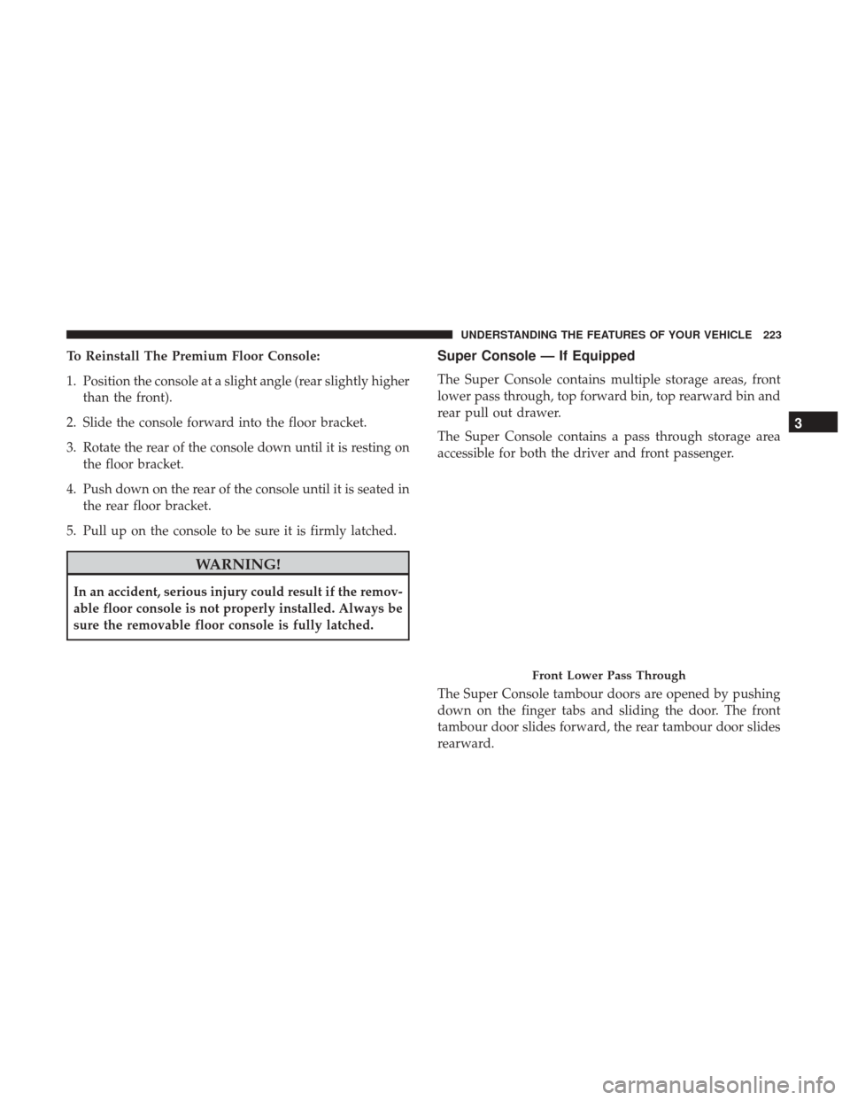
The Super Console contains a pass through storage area
accessible for both the driver and front passenger.
The Super Console tambour doors are opened by pushing
down on the finger tabs and sliding the door. The front
tambour door slides forward, the rear tambour door slides
rearward.
Front Lower Pass Through
3
UNDERSTANDING THE FEATURES OF YOUR VEHICLE 223
Page 226 of 530
NOTE:The front cupholder light ring and pass through
lighting is controlled by a dimming switch located on the
instrument panel, refer to “Lights” in “Understanding The
Features Of Your Vehicle” for further information.
Located in the back of the Super Console is a storage
drawer and cupholders for the rear passengers.
REAR WINDOW FEATURES
Rear Window Defroster
The rear window defroster button is located on the
climate control (Mode) knob. Push this button to
turn on the rear window defroster and the heated outside
mirrors (if equipped). An indicator in the button will
illuminate when the rear window defroster is on. The rear
window defroster automatically turns off after approxi-
mately 10 minutes. For an additional five minutes of
operation, push the button a second time.
Super Console
1 — Front Sliding Tambour Door
2 — Cupholder Light Ring
3 — Rear Sliding Tambour Door
Rear Drawer Storage
224 UNDERSTANDING THE FEATURES OF YOUR VEHICLE
Page 235 of 530

UNDERSTANDING YOUR INSTRUMENT PANEL
CONTENTS
�INSTRUMENT PANEL FEATURES ...........236
� INSTRUMENT CLUSTER ..................237
� WARNING AND INDICATOR LIGHTS ........241
▫ Red Telltale Indicator Lights ...............242
▫ Yellow Telltale Indicator Lights .............249
▫ Green Telltale Indicator Lights ..............256
▫ Blue Telltale Indicator Lights ...............257
▫ White Telltale Indicator Lights ..............258
� INSTRUMENT CLUSTER DISPLAY— IF
EQUIPPED ............................259
▫ Instrument Cluster Display ................260
▫ Oil Change Required ....................263
▫ Fuel Economy ........................ .264
▫ Vehicle Speed ........................ .265▫
Trip Info ............................ .265
▫ Tire Pressure ..........................266
▫ Units ............................... .266
▫ Vehicle Info (Customer Information Features) . . .266
▫ Messages # .......................... .266
▫ Compass / Temperature Display ...........267
▫ Turn Menu Off ........................ .269
▫ Customer-Programmable Features
(System Setup) ........................269
� CYBERSECURITY ........................274
� RADIO 430/430N CD/DVD/HDD/NAV — IF
EQUIPPED ............................275
▫ Operating Instructions (Voice Command System) —
If Equipped .......................... .2754
Page 238 of 530
INSTRUMENT PANEL FEATURES
Instrument Panel
1 — Air Vents5 — Upper Glove Compartment 9 — Storage Bin 13 — Hood Release
2 — Instrument Cluster 6 — Lower Glove Compartment 10 — Cup Holders 14 — Dimmer Switch
3 — Gear Selector 7 — Climate Controls11 — Switch Bank15 — Headlight Switch
4 — Radio 8 — DVD – If Equipped12 — Ignition Switch
236 UNDERSTANDING YOUR INSTRUMENT PANEL
Page 243 of 530

grades. It should not be allowed to exceed the upper
limits of the normal operating range.
WARNING!
A hot engine cooling system is dangerous. You or
others could be badly burned by steam or boiling
coolant. You may want to call an authorized dealer for
service if your vehicle overheats. If you decide to look
under the hood yourself, see “Maintaining Your Ve-
hicle”. Follow the warnings under the Cooling System
Pressure Cap paragraph.
CAUTION!
Driving with a hot engine cooling system could dam-
age your vehicle. If the temperature gauge reads “H”
pull over and stop the vehicle. Idle the vehicle with the
air conditioner turned off until the pointer drops back
into the normal range. If the pointer remains on the
“H”, turn the engine off immediately and call an
authorized dealer for service.
WARNING AND INDICATOR LIGHTS
IMPORTANT:The warning / indicator lights switch on in
the instrument panel together with a dedicated message
and/or acoustic signal when applicable. These indications
are indicative and precautionary and as such must not be
considered as exhaustive and/or alternative to the infor-
mation contained in the Owner ’s Manual, which you are
advised to read carefully in all cases. Always refer to the
information in this chapter in the event of a failure indica-
tion.
All active telltales will display first if applicable. The
system check menu may appear different based upon
equipment options and current vehicle status. Some tell-
tales are optional and may not appear.
4
UNDERSTANDING YOUR INSTRUMENT PANEL 241
Page 244 of 530

Red Telltale Indicator Lights
Air Bag Warning Light
Red TelltaleLight What It Means
Air Bag Warning Light
This light will turn on for four to eight seconds as a bulb check when the ignition is placed in the
ON/RUN position. If the light is either not on during startup, stays on, or turns on while driv-
ing, have the system inspected at an authorized dealer as soon as possible. This light will illumi-
nate with a single chime when a fault with the Air Bag Warning Light has been detected, it will
stay on until the fault is cleared. If the light comes on intermittently or remains on while driving,
have an authorized dealer service the vehicle immediately.
Seat Belt Reminder Warning Light
Red Telltale
Light What It Means
Seat Belt Reminder Warning Light
When the ignition is first placed in the ON/RUN position, if the driver ’s seat belt is unbuckled, a
chime will sound and the light will turn on. When driving, if the driver or front passenger seat
belt remains unbuckled, the Seat Belt Reminder Light will flash or remain on continuously and a
chime will sound. Refer to “Occupant Restraints” in “Things To Know Before Starting Your Ve-
hicle” for further information.
242 UNDERSTANDING YOUR INSTRUMENT PANEL