Page 228 of 530
The crossbars and side rails are designed to carry weight
on vehicles equipped with a luggage rack. The load must
not exceed 150 lbs (68 kg), and should be uniformly
distributed over the luggage rack crossbars.
NOTE:
•Crossbars are error-proofed and cannot be deployed or
stowed in the incorrect positions.
• To help control wind noise, stow the crossbars in the side
rails when they are not in use.
Deploying The Crossbars
To deploy the crossbars, completely loosen the thumb
screws at both ends of the crossbar and lift the crossbar
from its stowed position in the side rail. Repeat with
crossbar on the opposite side.
CAUTION!
Use care when removing and handling the crossbars to
prevent damage to the vehicle.
Crossbar Stowed In Side Rail
Loosening Crossbars
226 UNDERSTANDING THE FEATURES OF YOUR VEHICLE
Page 266 of 530
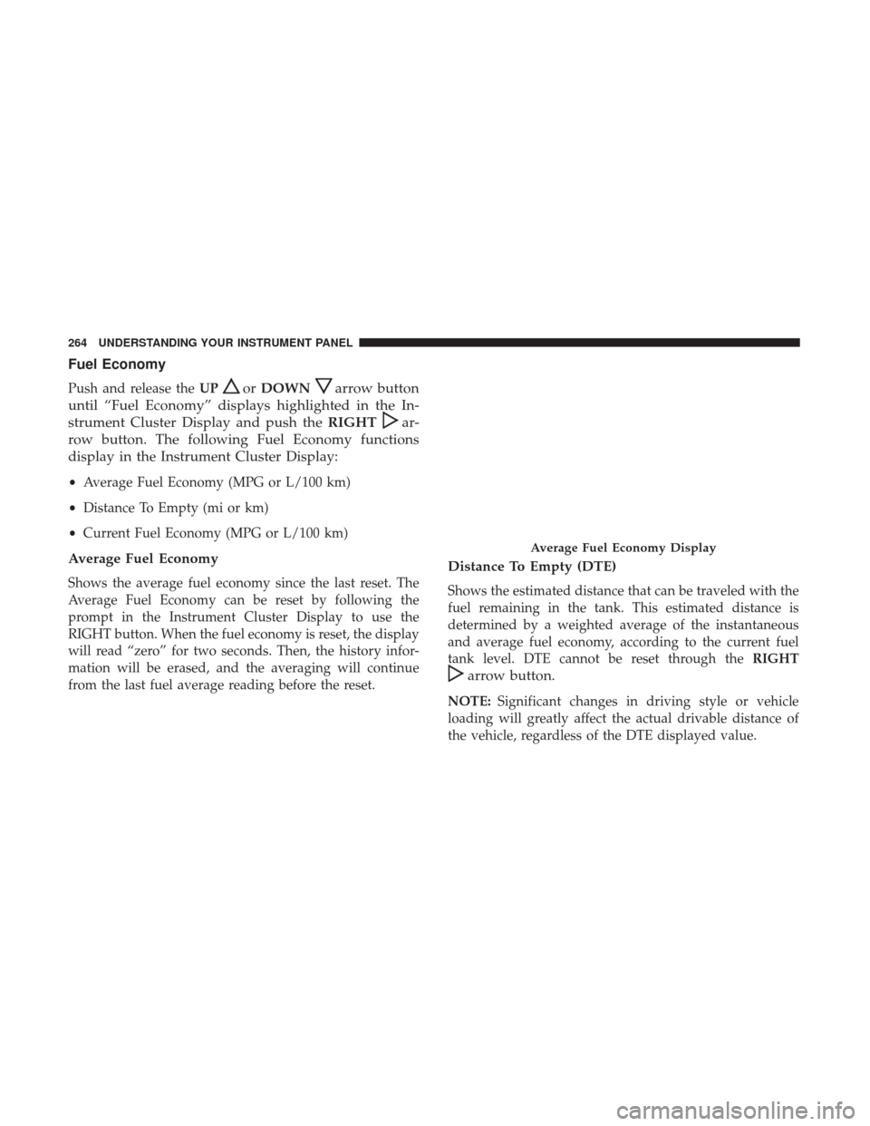
Fuel Economy
Push and release theUPorDOWNarrow button
until “Fuel Economy” displays highlighted in the In-
strument Cluster Display and push the RIGHT
ar-
row button. The following Fuel Economy functions
display in the Instrument Cluster Display:
• Average Fuel Economy (MPG or L/100 km)
• Distance To Empty (mi or km)
• Current Fuel Economy (MPG or L/100 km)
Average Fuel Economy
Shows the average fuel economy since the last reset. The
Average Fuel Economy can be reset by following the
prompt in the Instrument Cluster Display to use the
RIGHT button. When the fuel economy is reset, the display
will read “zero” for two seconds. Then, the history infor-
mation will be erased, and the averaging will continue
from the last fuel average reading before the reset.
Distance To Empty (DTE)
Shows the estimated distance that can be traveled with the
fuel remaining in the tank. This estimated distance is
determined by a weighted average of the instantaneous
and average fuel economy, according to the current fuel
tank level. DTE cannot be reset through the RIGHT
arrow button.
NOTE:Significant changes in driving style or vehicle
loading will greatly affect the actual drivable distance of
the vehicle, regardless of the DTE displayed value.
Average Fuel Economy Display
264 UNDERSTANDING YOUR INSTRUMENT PANEL
Page 370 of 530

Trailer Sway Control (TSC)
TSC uses sensors in the vehicle to recognize an excessively
swaying trailer and will take the appropriate actions to
attempt to stop the sway. TSC will become active automati-
cally once an excessively swaying trailer is recognized.
Note that TSC cannot stop all trailers from swaying.
Always use caution when towing a trailer and follow the
trailer tongue weight recommendations. Refer to “Trailer
Towing” in this section for further information. When TSC
is functioning, the “ESC Activation/Malfunction Indicator
Light” will flash, the engine power may be reduced and
you may feel the brakes being applied to individual wheels
to attempt to stop the trailer from swaying. TSC is disabled
when the ESC system is in the “Partial Off” modes.
WARNING!
If TSC activates while driving, slow the vehicle down,
stop at the nearest safe location, and adjust the trailer
load to eliminate trailer sway.
TIRE SAFETY INFORMATION
Tire Markings
1 — U.S. DOT Safety Standards
Code (TIN)4 — Maximum Load
2 — Size Designation 5 — Maximum Pressure
3 — Service Description 6 — Treadwear, Traction and Temperature Grades
368 STARTING AND OPERATING
Page 377 of 530
WARNING!
•Overloading of your tires is dangerous. Overloading
can cause tire failure, affect vehicle handling, and
increase your stopping distance. Use tires of the
recommended load capacity for your vehicle. Never
overload them.
• Improperly inflated tires are dangerous and can
cause collisions. Under-inflation increases tire flex-
ing and can result in over-heating and tire failure.
Over-inflation reduces a tire’s ability to cushion
shock. Objects on the road and chuck holes can cause
damage that results in tire failure. Unequal tire
pressures can cause steering problems. You could
lose control of your vehicle. Over-inflated or under-
inflated tires can affect vehicle handling and can fail
suddenly, resulting in loss of vehicle control. Always
drive with each tire inflated to the recommended
cold tire inflation pressure.
Tire And Loading Information Placard
This placard tells you important information about the:
1. Number of people that can be carried in the vehicle.
2. Total weight your vehicle can carry.
3. Tire size designed for your vehicle.
4. Cold tire inflation pressures for the front, rear, and spare
tires.
Tire And Loading Information Placard
5
STARTING AND OPERATING 375
Page 378 of 530
Loading
The vehicle maximum load on the tire must not exceed the
load carrying capacity of the tire on your vehicle. You will
not exceed the tire’s load carrying capacity if you adhere to
the loading conditions, tire size, and cold tire inflation
pressures specified on the Tire and Loading Information
placard in “Vehicle Loading” in the “Starting And Operat-
ing” section of this manual.
NOTE:Under a maximum loaded vehicle condition, gross
axle weight ratings (GAWRs) for the front and rear axles
must not be exceeded. For further information on GAWRs,
vehicle loading, and trailer towing, refer to “Vehicle Load-
ing” in the “Starting And Operating” section of this
manual.
To determine the maximum loading conditions of your
vehicle, locate the statement “The combined weight of
occupants and cargo should never exceed XXX kg or
XXX lbs” on the Tire and Loading Information placard. The
combined weight of occupants, cargo/luggage and trailer
tongue weight (if applicable) should never exceed the
weight referenced here.
Steps For Determining Correct Load Limit—
(1) Locate the statement “The combined weight of
occupants and cargo should never exceed XXX kg or
XXX lbs.” on your vehicle’s placard.
(2) Determine the combined weight of the driver and
passengers that will be riding in your vehicle.
(3) Subtract the combined weight of the driver and
passengers from XXX kg or XXX lbs.
376 STARTING AND OPERATING
Page 379 of 530
(4) The resulting figure equals the available amount of
cargo and luggage load capacity. For example, if “XXX”
amount equals 1400 lbs. and there will be five 150 lb
passengers in your vehicle, the amount of available
cargo and luggage load capacity is 650 lbs. (1400-750
(5x150) = 650 lbs.)
(5) Determine the combined weight of luggage and
cargo being loaded on the vehicle. That weight may not
safely exceed the available cargo and luggage load
capacity calculated in Step 4.
(6) If your vehicle will be towing a trailer, load from
your trailer will be transferred to your vehicle. Consult
this manual to determine how this reduces the available
cargo and luggage load capacity of your vehicle.Metric Example For Load Limit
For example, if “XXX” amount equals 635 kg and there will
be five 68 kg passengers in your vehicle, the amount of
available cargo and luggage load capacity is 295 kg (635-
340 (5x68) = 295 kg) as shown in step 4.
NOTE:
•If your vehicle will be towing a trailer, load from your
trailer will be transferred to your vehicle. The following
table shows examples on how to calculate total load,
cargo/luggage, and towing capacities of your vehicle
with varying seating configurations and number and
size of occupants. This table is for illustration purposes
only and may not be accurate for the seating and load
carry capacity of your vehicle.
• For the following example, the combined weight of
occupants and cargo should never exceed 865 lbs
(392 kg).
5
STARTING AND OPERATING 377
Page 408 of 530
NOTE:
•When the fuel nozzle “clicks” or shuts off, the fuel tank
is full.
• Tighten the fuel filler cap until you hear a “clicking”
sound. This is an indication that the fuel filler cap is
properly tightened.
• If the gas cap is not tightened properly, the MIL may
come on. Be sure the gas cap is tightened every time the
vehicle is refueled.
Loose Fuel Filler Cap Message
If the vehicle diagnostic system determines that the fuel
filler cap is loose, improperly installed, or damaged, a
“gASCAP” message will display in the odometer or a
“CHECK GASCAP” message will be displayed in the
instrument cluster. Refer to “Instrument Cluster Display”
in “Understanding Your Instrument Panel” for further
information. Tighten the fuel filler cap until a “clicking”
sound is heard. This is an indication that the fuel filler cap
is properly tightened. Refer to “Onboard Diagnostic Sys-
tem” in “Maintaining Your Vehicle” for further informa-
tion. If the problem continues, the message will appear the next
time the vehicle is started. See your authorized dealer as
soon as possible.
VEHICLE LOADING
As required by National Highway Traffic Safety Adminis-
tration regulations, your vehicle has a certification label
affixed to the driver’s side door or B-Pillar.
If seats are removed for carrying cargo, do not exceed the
specified GVWR and GAWR.
Vehicle Certification Label
Your vehicle has a Vehicle Certification Label affixed to the
drivers side B-Pillar or the rear of the driver ’s door.
The label contains the following information:
•
Name of manufacturer
• Month and year of manufacture
• Gross Vehicle Weight Rating (GVWR)
• Gross Axle Weight Rating (GAWR) front
• Gross Axle Weight Rating (GAWR) rear
406 STARTING AND OPERATING
Page 409 of 530
•Vehicle Identification Number (VIN)
• Type of vehicle
• Month Day and Hour of Manufacture (MDH)
The bar code allows a computer scanner to read the VIN.
Gross Vehicle Weight Rating (GVWR)
The GVWR is the total allowable weight of your vehicle.
This includes driver, passengers, and cargo. The total load
must be limited so that you do not exceed the GVWR.
Gross Axle Weight Rating (GAWR)
The GAWR is the maximum capacity of the front and rear
axles. Distribute the load over the front and rear axles
evenly. Make sure that you do not exceed either front or
rear GAWR.
WARNING!
Because the front wheels steer the vehicle, it is impor-
tant that you do not exceed the maximum front or rear
GAWR. A dangerous driving condition can result if
either rating is exceeded. You could lose control of the
vehicle and have a collision.
Tire Size
The tire size on the Vehicle Certification Label represents
the actual tire size on your vehicle. Replacement tires must
be equal to the load capacity of this tire size.
Rim Size
This is the rim size that is appropriate for the tire size
listed.
Inflation Pressure
This is the cold tire inflation pressure for your vehicle for
all loading conditions up to full GAWR.
Curb Weight
The curb weight of a vehicle is defined as the total weight
of the vehicle with all fluids, including vehicle fuel, at full
capacity conditions, and with no occupants or cargo loaded
into the vehicle. The front and rear curb weight values are
determined by weighing your vehicle on a commercial
scale before any occupants or cargo are added.
5
STARTING AND OPERATING 407