2017 BMW 6 SERIES GRAN COUPE service
[x] Cancel search: servicePage 214 of 261

4.Insert the sealant container on the com‐
pressor housing in an upright position.5.Screw the filling hose of the sealant con‐
tainer onto the tire valve of the nonworking
wheel.6.With the compressor switched off, insert
the plug into the power socket inside the
vehicle.7.With the ignition turned on or the engine
running, switch on the compressor.
ATTENTION
The compressor can overheat during ex‐
tended operation. There is a risk of damage to
property. Do not run the compressor for more
than 10 min.◀
Let the compressor run for approx. 3 to 8 mi‐
nutes to fill the tire with sealant and achieve a
tire inflation pressure of approx. 2.5 bar.
While the tire is being filled with sealant, the
tire inflation pressure may sporadically reach
approx. 5 bar. Do not switch off the compres‐
sor at this point.
If a tire inflation pressure of 2 bar is not
reached:
1.Switch off the compressor.2.Unscrew the filling hose from the wheel.3.Drive 33 ft/10 m forward and back to dis‐
tribute the sealant in the tire.4.Inflate the tire again using the compressor.
If a tire inflation pressure of 2 bar cannot be
reached, contact your dealer’s service cen‐
ter or another qualified service center or
repair shop.
Stowing the Mobility System
1.Unscrew the filling hose of the sealant con‐
tainer from the wheel.2.Unscrew the connection hose of the com‐
pressor from the sealant container.3.Connect the filling hose of the sealant con‐
tainer previously connected to the tireSeite 214MobilityWheels and tires214
Online Edition for Part no. 01 40 2 969 305 - II/16
Page 215 of 261

valve with the available connector on the
sealant container.
This prevents leftover sealant from escap‐
ing from the container.4.Wrap the empty sealant container in suita‐
ble material to avoid dirtying the cargo
area.5.Stow the Mobility System back in the vehi‐
cle.
Distributing the sealant
Immediately drive approx. 5 miles/10 km to en‐
sure that the sealant is evenly distributed in the
tire.
Do not exceed a speed of 50 mph/80 km/h.
If possible, do not drive at speeds less than
12 mph/20 km/h.
To correct the tire inflation pressure
1.Stop at a suitable location.2.Screw the connection hose of the com‐
pressor directly onto the tire valve stem.3.Insert the connector into the power socket
inside the vehicle.4.Correct the tire inflation pressure to
2.5 bar.▷Increase pressure: with the ignition
turned on or the engine running, switch
on the compressor.▷To reduce the pressure: press the but‐
ton on the compressor.
Continuing the trip
Do not exceed the maximum permissible
speed of 50 mph/80 km/h.
Reinitialize the Flat Tire Monitor.
Reinitialize the Tire Pressure Monitor.
Replace the nonworking tire and the sealant
container of the Mobility System as soon as
possible.
Snow chains
Fine-link snow chains The manufacturer of your vehicle recommends
use of fine-link snow chains. Certain types of
fine-link snow chains have been tested by the
manufacturer of the vehicle and recommended
as road-safe and suitable.
Information regarding suitable snow chains is
available from a dealer’s service center or an‐
other qualified service center or repair shop.
Use WARNING
With the mounting of snow chains on un‐
suitable tires, the snow chains can come into
contact with vehicle parts. There is a risk of ac‐
cidents or a risk of property damage. Only
mount snow chains on tires that are desig‐
nated by their manufacturer as suitable for the
use of snow chains.◀
Use only in pairs on the rear wheels, equipped
with the tires of the following size:▷225/55 R 17.▷245/45 R 18.
Follow the snow chain manufacturer's instruc‐
tions.
Make sure that the snow chains are always
sufficiently tight. Re-tighten as needed ac‐
cording to the snow chain manufacturer's in‐
structions.
Do not initialize the Flat Tire Monitor after
mounting snow chains, as doing so may result
in incorrect readings.
Do not initialize the Tire Pressure Monitor after
mounting snow chains, as doing so may result
in incorrect readings.
When driving with snow chains, briefly activate
Dynamic Traction Control if needed.
Seite 215Wheels and tiresMobility215
Online Edition for Part no. 01 40 2 969 305 - II/16
Page 217 of 261
Engine compartmentVehicle features and optionsThis chapter describes all standard, country-
specific and optional features offered with the
series. It also describes features that are not
necessarily available in your car, e. g., due tothe selected options or country versions. This
also applies to safety-related functions and
systems. The respectively applicable country
provisions must be observed when using the
respective features and systems.
Important features in the engine compartment
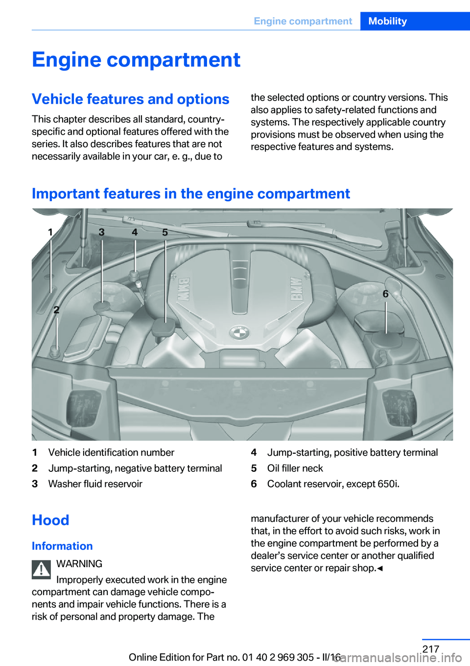
1Vehicle identification number2Jump-starting, negative battery terminal3Washer fluid reservoir4Jump-starting, positive battery terminal5Oil filler neck6Coolant reservoir, except 650i.Hood
Information WARNING
Improperly executed work in the engine
compartment can damage vehicle compo‐
nents and impair vehicle functions. There is a
risk of personal and property damage. Themanufacturer of your vehicle recommends
that, in the effort to avoid such risks, work in
the engine compartment be performed by a
dealer’s service center or another qualified
service center or repair shop.◀Seite 217Engine compartmentMobility217
Online Edition for Part no. 01 40 2 969 305 - II/16
Page 221 of 261
ATTENTION
Too much engine oil can damage the en‐
gine or the catalytic converter. There is a risk
of damage to property. Do not add too much
engine oil. When too much engine oil is added,
have oil level corrected by a dealer’s service
center or another qualified service center or re‐
pair shop.◀
Detailed measurement
The concept In the detailed measurement the engine oil
level is checked when the vehicle is stationary,
and displayed via a scale.
Gasoline engine:
If the engine oil level reaches the minimum
level, a check control message is displayed.
During the measurement, the idle speed is in‐
creased somewhat.
General information
A detailed measurement is only possible with
certain engines.
Requirements▷Vehicle is parked in a horizontal position.▷Steptronic transmission: selector lever in
selector lever position N or P and accelera‐
tor pedal not depressed.▷Engine is running and is at operating tem‐
perature.
Performing a detailed measurement
In order to perform a detailed measurement of
the engine oil level:
1."Vehicle info"2."Vehicle status"3. "Measure engine oil level"4."Start measurement"
The engine oil level is checked and displayed
via a scale.
Time: approx. 1 minute.
Adding engine oil Information WARNING
Operating materials, e.g., oils, greases,
coolants, fuels, can contain harmful ingredi‐
ents. There is a risk of injury or danger to life.
Observe the instructions on the containers.
Avoid the contact of articles of clothing, skin or
eyes with operating materials. Do not refill op‐
erating materials into different bottles. Store
operating materials out of reach of children.◀
ATTENTION
Too low of an engine oil level causes en‐
gine damage. There is a risk of damage to
property.
Add engine oil within the next
125 miles/200 km.◀
ATTENTION
Too much engine oil can damage the en‐
gine or the catalytic converter. There is a risk
of damage to property. Do not add too much
engine oil. When too much engine oil is added,
have oil level corrected by a dealer’s service
center or another qualified service center or re‐
pair shop.◀
General information Only add engine oil when the message is dis‐
played in the instrument cluster. The quantity
to be added is indicated in the message dis‐
played in the instrument cluster.
Switch off the ignition and safely park the vehi‐
cle before engine oil is added.
Take care not to add too much engine oil.
Overview The oil filler neck is located in the engine com‐
partment, refer to page 217.Seite 221Engine oilMobility221
Online Edition for Part no. 01 40 2 969 305 - II/16
Page 222 of 261
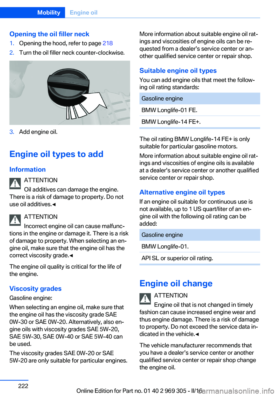
Opening the oil filler neck1.Opening the hood, refer to page 2182.Turn the oil filler neck counter-clockwise.3.Add engine oil.
Engine oil types to add
Information ATTENTION
Oil additives can damage the engine.
There is a risk of damage to property. Do not
use oil additives.◀
ATTENTION
Incorrect engine oil can cause malfunc‐
tions in the engine or damage it. There is a risk
of damage to property. When selecting an en‐
gine oil, make sure that the engine oil has the
correct viscosity grade.◀
The engine oil quality is critical for the life of
the engine.
Viscosity gradesGasoline engine:
When selecting an engine oil, make sure that
the engine oil has the viscosity grade SAE
0W-30 or SAE 0W-20. Alternatively, also en‐
gine oils with viscosity grades SAE 5W-20,
SAE 5W-30, SAE 0W-40 or SAE 5W-40 can
be used.
The viscosity grades SAE 0W-20 or SAE
5W-20 are only suitable for particular engines.
More information about suitable engine oil rat‐
ings and viscosities of engine oils can be re‐
quested from a dealer’s service center or an‐
other qualified service center or repair shop.
Suitable engine oil types
You can add engine oils that meet the follow‐
ing oil rating standards:Gasoline engineBMW Longlife-01 FE.BMW Longlife-14 FE+.
The oil rating BMW Longlife-14 FE+ is only
suitable for particular gasoline motors.
More information about suitable engine oil rat‐
ings and viscosities of engine oils is available
at a dealer’s service center or another qualified
service center or repair shop.
Alternative engine oil typesIf an engine oil suitable for continuous use is
not available, up to 1 US quart/liter of an en‐ gine oil with the following oil rating can be
added:
Gasoline engineBMW Longlife-01.API SL or superior oil rating.
Engine oil change
ATTENTION
Engine oil that is not changed in timely
fashion can cause increased engine wear and
thus engine damage. There is a risk of damage
to property. Do not exceed the service data in‐
dicated in the vehicle.◀
The vehicle manufacturer recommends that
you have a dealer’s service center or another
qualified service center or repair shop change
the engine oil.
Seite 222MobilityEngine oil222
Online Edition for Part no. 01 40 2 969 305 - II/16
Page 224 of 261
CoolantVehicle features and optionsThis chapter describes all standard, country-
specific and optional features offered with the
series. It also describes features that are not
necessarily available in your car, e. g., due to
the selected options or country versions. This
also applies to safety-related functions and
systems. The respectively applicable country
provisions must be observed when using the
respective features and systems.
Information WARNING
With the engine hot and the cooling sys‐
tem open, coolant can escape and lead to
scalding. There is a a risk of injury. Only open
the cooling system with the engine cooled
down.◀
WARNING
Additives are harmful and incorrect addi‐
tives can damage the engine. There is a risk of
injury and risk of property damage. Do not al‐
low additives to come into contact with skin,
eyes or articles of clothing. Use suitable addi‐
tives only.◀
Coolant consists of water and additives.
Not all commercially available additives are
suitable for the vehicle. Information about suit‐
able additives is available from a dealer’s serv‐
ice center or another qualified service center or
repair shop.
Coolant level
General information
If there is no Min. and Max. mark in the filler
neck of the coolant reservoir, have the coolantlevel checked if needed by a dealer’s service
center or another qualified service center or re‐
pair shop and add coolant as needed.
Overview
Depending on the engine installation, the cool‐
ant reservoir is located on the right side or the
left side of the engine compartment.
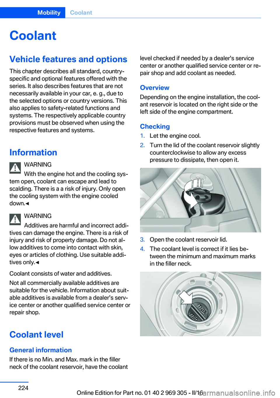
Checking1.Let the engine cool.2.Turn the lid of the coolant reservoir slightly
counterclockwise to allow any excess
pressure to dissipate, then open it.3.Open the coolant reservoir lid.4.The coolant level is correct if it lies be‐
tween the minimum and maximum marks
in the filler neck.Seite 224MobilityCoolant224
Online Edition for Part no. 01 40 2 969 305 - II/16
Page 226 of 261

MaintenanceVehicle features and options
This chapter describes all standard, country-
specific and optional features offered with the
series. It also describes features that are not
necessarily available in your car, e. g., due to
the selected options or country versions. This
also applies to safety-related functions and
systems. The respectively applicable country
provisions must be observed when using the
respective features and systems.
BMW maintenance system The maintenance system indicates required
maintenance measures, and thereby provides
support in maintaining road safety and the op‐
erational reliability of the vehicle.
In some cases scopes and intervals may vary
according to the country-specific version. Re‐
placement work, spare parts, fuels and lubri‐
cants and wear materials are calculated sepa‐
rately. Further information is available from a
dealer’s service center or another qualified
service center or repair shop.
Condition Based ServiceCBS
Sensors and special algorithms take into ac‐
count the driving conditions of the vehicle.
Based on this, Condition Based Service recog‐
nizes the maintenance requirements.
The system makes it possible to adapt the
amount of maintenance corresponding to your
user profile.
Information on service requirements can be
displayed on the Control Display.Service data in the remote control
Information on the required maintenance is
continuously stored in the remote control. The dealer’s service center can read this data out
and suggest a maintenance scope for the vehi‐
cle.
Therefore, hand the service advisor the remote
control with which the vehicle was driven most
recently.
Storage periods Storage periods during which the vehicle bat‐
tery was disconnected are not taken into ac‐
count.
If this occurs, have a dealer's service center or
another qualified service center or repair shop
update the time-dependent maintenance pro‐
cedures, such as checking brake fluid and, if
necessary, changing the engine oil and the mi‐
crofilter/activated-charcoal filter.
Service and WarrantyInformation Booklet for US
models and Warranty and
Service Guide Booklet for
Canadian models
Please consult your Service and Warranty In‐
formation Booklet for US models and Warranty
and Service Guide Booklet for Canadian mod‐
els for additional information on service re‐
quirements.
The manufacturer of your vehicle recommends
that maintenance and repair be performed by a
dealer’s service center or another qualified
service center or repair shop. Records of regu‐
lar maintenance and repair work should be re‐
tained.Seite 226MobilityMaintenance226
Online Edition for Part no. 01 40 2 969 305 - II/16
Page 227 of 261
Socket for OBD Onboard
Diagnosis
Information ATTENTION
The socket for Onboard Diagnosis is an
intricate component intended to be used in
conjunction with specialized equipment to
check the vehicle’s primary emissions system.
Improper use of the socket for Onboard Diag‐
nosis, or contact with the socket for Onboard
Diagnosis for other than its intended purpose,
can cause vehicle malfunctions and creates
risks of personal and property damage. Given
the foregoing, the manufacture of your vehicle
strongly recommends that access to the
socket for Onboard Diagnosis be limited to a
dealer's service center or another qualified
service center or repair shop or other persons
that have the specialized training and equip‐
ment for purposes of properly utilizing the
socket for Onboard Diagnosis.◀
Position
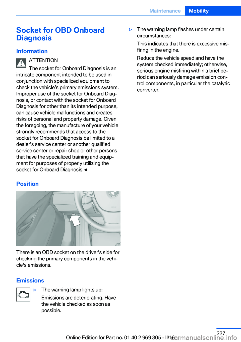
There is an OBD socket on the driver's side for
checking the primary components in the vehi‐
cle's emissions.
Emissions
▷The warning lamp lights up:
Emissions are deteriorating. Have
the vehicle checked as soon as
possible.▷The warning lamp flashes under certain
circumstances:
This indicates that there is excessive mis‐
firing in the engine.
Reduce the vehicle speed and have the
system checked immediately; otherwise,
serious engine misfiring within a brief pe‐
riod can seriously damage emission con‐
trol components, in particular the catalytic
converter.Seite 227MaintenanceMobility227
Online Edition for Part no. 01 40 2 969 305 - II/16