2017 BMW 6 SERIES GRAN COUPE fuel
[x] Cancel search: fuelPage 82 of 261

▷Messages, e.g. Check Control, refer to
page 85.▷Current fuel consumption, refer to
page 90.▷Navigation display, see Owner's Manual for
Navigation, Entertainment and Communi‐
cation.▷Range, refer to page 90.▷Status, Driving Dynamics Control, refer to
page 137.▷Service requirements, refer to page 91.▷Speed limit detection, refer to page 92.▷Time, refer to page 90.
Multifunctional instrument display
The concept
The instrument display is a variable display. In
the event of a program change, the display
rendition adapts to the respective program
through the Driving Dynamics Control. The
change of the display type can be deactivated
via iDrive.Some of the displays in the instrument display
may differ from the way they are shown in this
Owner's Manual.
Overview
1Fuel gauge 892Indicator/warning lights 853Speedometer4Variable displays5Tachometer 89
Selection lists 93
ECO PRO displays 1916Engine oil temperature 89Seite 82ControlsDisplays82
Online Edition for Part no. 01 40 2 969 305 - II/16
Page 83 of 261

7Onboard computer 948Reset miles 89Switching the change of display on
and off
You can set whether the instrument display
automatically changes to the ECO PRO or
SPORT in the display when you switch driving
modes.
On the Control Display:1."Settings"2."Instrument cluster"3."ECO PRO Info"Or "Driving mode view"
With Professional Navigation System:
switching zoom function on/off
You can program whether the current speed is
to appear enlarged in the speedometer.
On the Control Display:
1."Settings"2."Instrument cluster"3."Magnifier function"
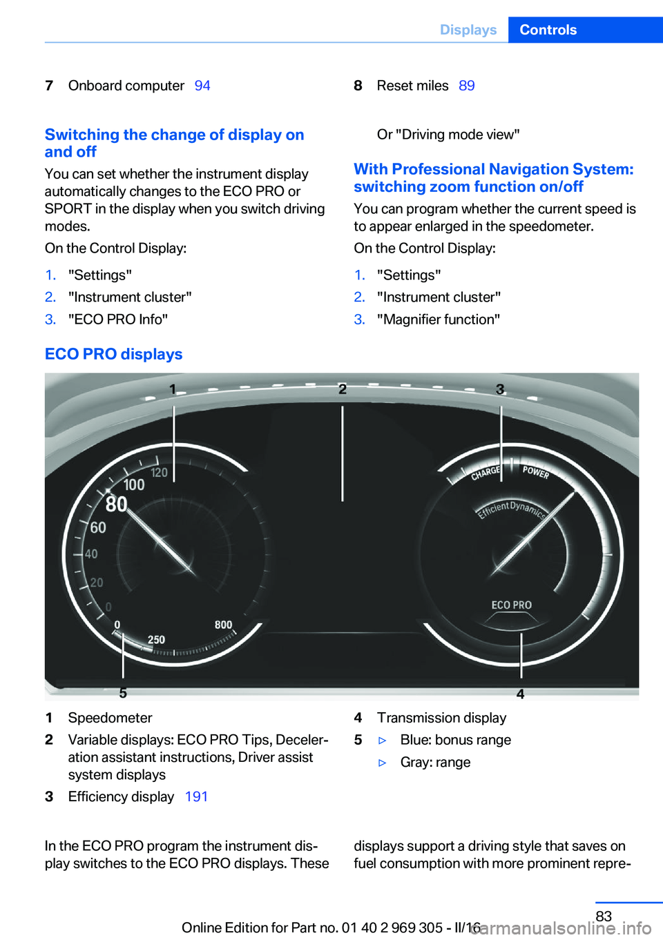
ECO PRO displays
1Speedometer2Variable displays: ECO PRO Tips, Deceler‐
ation assistant instructions, Driver assist
system displays3Efficiency display 1914Transmission display5▷Blue: bonus range▷Gray: rangeIn the ECO PRO program the instrument dis‐
play switches to the ECO PRO displays. Thesedisplays support a driving style that saves on
fuel consumption with more prominent repre‐Seite 83DisplaysControls83
Online Edition for Part no. 01 40 2 969 305 - II/16
Page 85 of 261

Display in the instrument display▷Current engine speed is displayed in the
tachometer.▷Arrow 1: successive yellow illuminated
fields indicate an increase in the speed.▷Arrow 2: successive orange illuminated
fields indicate the upcoming shift moment.▷Arrow 3: fields are illuminated in red. Do
not wait any further to shift.
When the maximum possible speed is
reached, the entire display flashes. When the
maximum speed is exceeded, the supply of
fuel is interrupted in order to protect the en‐
gine.
Check Control The conceptThe Check Control system monitors functions
in the vehicle and notifies you of malfunctions
in the monitored systems.
A Check Control message is displayed as a
combination of indicator or warning lights and
text messages in the instrument cluster and in
the Head-up Display.
In addition, an acoustic signal may sound and a
text message may appear on the Control Dis‐
play.
Indicator/warning lights
General information
The indicator and warning lights in the instru‐
ment cluster can light up in a variety of combi‐
nations and colors.
Several of the lights are checked for proper
functioning and light up temporarily when the
engine is started or the ignition is switched on.
Red lights
Safety belt reminder Safety belt on the driver's side is not
buckled. For some country-specific
models: passenger belt is not worn or
objects are detected on the front passenger
seat.
Flashing or illuminated: safety belt on the
driver or passenger side is not buckled. The
safety belt reminder can also be activated if
objects are placed on the front passenger seat.
Make sure that the safety belts are positioned
correctly.
Airbag system Airbag system and belt tensioner are
not working.
Have the vehicle checked immediately
by a dealer’s service center or another quali‐
fied service center or repair shop.
Parking brake The parking brake is set.
For additional information, refer to Re‐
lease parking brake, refer to page 71.
Brake systemSeite 85DisplaysControls85
Online Edition for Part no. 01 40 2 969 305 - II/16
Page 89 of 261

▷Other Check Control messages are faded
automatically after approx. 20 seconds.
They are stored and can be displayed
again later.
Displaying stored Check Control
messages
On the Control Display:
1."Vehicle info"2."Vehicle status"3. "Check Control"4.Select the text message.
Messages after trip completion Special messages displayed while driving are
displayed again after the ignition is switched
off.
Fuel gauge Vehicle tilt position may cause
the display to vary.
Depending on the equipment
version, the arrow beside the
fuel pump symbol shows which
side of the vehicle the fuel filler flap is on.
Information on refueling, refer to page 198.
Tachometer
Always avoid engine speeds in the red warning
field. In this range, the fuel supply is inter‐
rupted to protect the engine.
Engine oil temperature
▷Cold engine: the pointer is at
the low temperature end.
Drive at moderate engine
and vehicle speeds.▷Normal operating temperature: the pointer
is in the middle or in the left half of the tem‐
perature display.▷Hot engine: the pointer is at the high end of
the temperature range. In addition, a Check
Control message is displayed.
Coolant temperature
If the coolant along with the engine becomes
too hot, a Check Control message is displayed.
Check the coolant level.
Odometer and trip odometer Display
▷Odometer, arrow 1.▷Trip odometer, arrow 2.
Show/reset kilometers Press the knob.
▷When the ignition is
switched off, the time, the
external temperature and
the odometer are displayed.▷When the ignition is switched on, the trip
odometer is reset.
External temperature
If the indicator drops to
+37 ℉/+3 ℃ or lower, a signal
sounds.
A Check Control message is displayed.
There is an increased risk of ice on roads.
Seite 89DisplaysControls89
Online Edition for Part no. 01 40 2 969 305 - II/16
Page 90 of 261

WARNING
Even at temperatures above +37 ℉/+3 ℃
there can be a danger of icy roads, e.g., on
bridges or shady sections of road. There is risk
of an accident. Adjust your driving style to the
weather conditions at low temperatures.◀
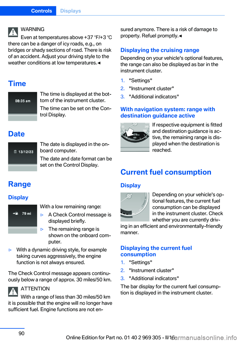
Time The time is displayed at the bot‐
tom of the instrument cluster.
The time can be set on the Con‐
trol Display.
Date The date is displayed in the on‐
board computer.
The date and date format can be
set on the Control Display.
Range Display With a low remaining range:▷A Check Control message is
displayed briefly.▷The remaining range is
shown on the onboard com‐
puter.▷With a dynamic driving style, for example
taking curves aggressively, the engine
function is not always ensured.
The Check Control message appears continu‐
ously below a range of approx. 30 miles/50 km.
ATTENTION
With a range of less than 30 miles/50 km
it is possible that the engine will no longer have
sufficient fuel. Engine functions are not en‐
sured anymore. There is a risk of damage to
property. Refuel promptly.◀
Displaying the cruising range Depending on your vehicle's optional features,
the range can also be displayed as bar in the
instrument cluster.1."Settings"2."Instrument cluster"3."Additional indicators"
With navigation system: range with destination guidance active
If respective equipment is fitted
and destination guidance is ac‐
tive, the remaining range is dis‐ played when the destination is
reached.
Current fuel consumption
Display Depending on your vehicle's op‐
tional features, the current fuel
consumption can be displayed
in the instrument cluster. Check
whether you are currently driv‐
ing in an efficient and environmentally-friendly
manner.
Displaying the current fuel
consumption
1."Settings"2."Instrument cluster"3."Additional indicators"
The bar display for the current fuel consump‐
tion is displayed in the instrument cluster.
Seite 90ControlsDisplays90
Online Edition for Part no. 01 40 2 969 305 - II/16
Page 91 of 261

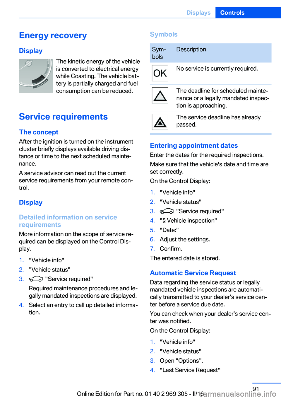
Energy recoveryDisplay The kinetic energy of the vehicle
is converted to electrical energy while Coasting. The vehicle bat‐
tery is partially charged and fuel
consumption can be reduced.
Service requirements The concept
After the ignition is turned on the instrument
cluster briefly displays available driving dis‐
tance or time to the next scheduled mainte‐
nance.
A service advisor can read out the current
service requirements from your remote con‐
trol.
Display
Detailed information on service
requirements
More information on the scope of service re‐
quired can be displayed on the Control Dis‐
play.1."Vehicle info"2."Vehicle status"3. "Service required"
Required maintenance procedures and le‐
gally mandated inspections are displayed.4.Select an entry to call up detailed informa‐
tion.SymbolsSym‐
bolsDescriptionNo service is currently required.The deadline for scheduled mainte‐
nance or a legally mandated inspec‐
tion is approaching.The service deadline has already
passed.
Entering appointment dates
Enter the dates for the required inspections.
Make sure that the vehicle's date and time are
set correctly.
On the Control Display:
1."Vehicle info"2."Vehicle status"3. "Service required"4."§ Vehicle inspection"5."Date:"6.Adjust the settings.7.Confirm.
The entered date is stored.
Automatic Service Request
Data regarding the service status or legally
mandated vehicle inspections are automati‐
cally transmitted to your dealer’s service cen‐
ter before a service due date.
You can check when your dealer’s service cen‐
ter was notified.
On the Control Display:
1."Vehicle info"2."Vehicle status"3.Open "Options".4."Last Service Request"Seite 91DisplaysControls91
Online Edition for Part no. 01 40 2 969 305 - II/16
Page 92 of 261

Gear shift indicatorThe conceptThe system recommends the most fuel effi‐
cient gear for the current driving situation.
General information
Depending on the vehicle's features and coun‐
try version of the vehicle, the gear shift indica‐
tor is active in the manual mode of the Step‐
tronic transmission.
Suggestions to shift gear up or down are dis‐
played in the instrument cluster.
On vehicles without a gear shift indicator, the
engaged gear is displayed.
DisplayingExampleDescriptionFuel efficient gear is set.Shift into fuel efficient gear.
Speed limit detection
The concept
Speed limit detection
Speed limit detection shows the current maxi‐
mum permitted speed in the instrument clus‐
ter. The camera in the area of the interior mir‐
ror detects traffic signs at the edge of the road
as well as variable overhead sign posts. Traffic
signs with extra symbols for wet road condi‐
tions, etc. are also detected and compared
with the vehicle's onboard data, such as for the
rain sensor, and will be displayed depending
on the situation. The system takes into ac‐
count the information stored in the navigation
system and also displays speed limits present
on routes without signs.
Information WARNING
The system does not release from the
personal responsibility to correctly assess visi‐
bility and traffic situation. There is risk of an ac‐
cident. Adjust the driving style to the traffic
conditions. Watch traffic closely and actively
intervene in the respective situations.◀
Overview
Camera
The camera is installed near the interior mirror.
Keep the windshield in the area behind the in‐
terior mirror clean and clear.
Switching on/off On the Control Display:
1."Settings"2."Instrument cluster"3."Speed limit information"
If speed limit detection is switched on, it can
be displayed on the CID (central information
display) in the instrument cluster via the on‐
board computer.
Display
The following is displayed in the instrument
cluster:
Seite 92ControlsDisplays92
Online Edition for Part no. 01 40 2 969 305 - II/16
Page 94 of 261

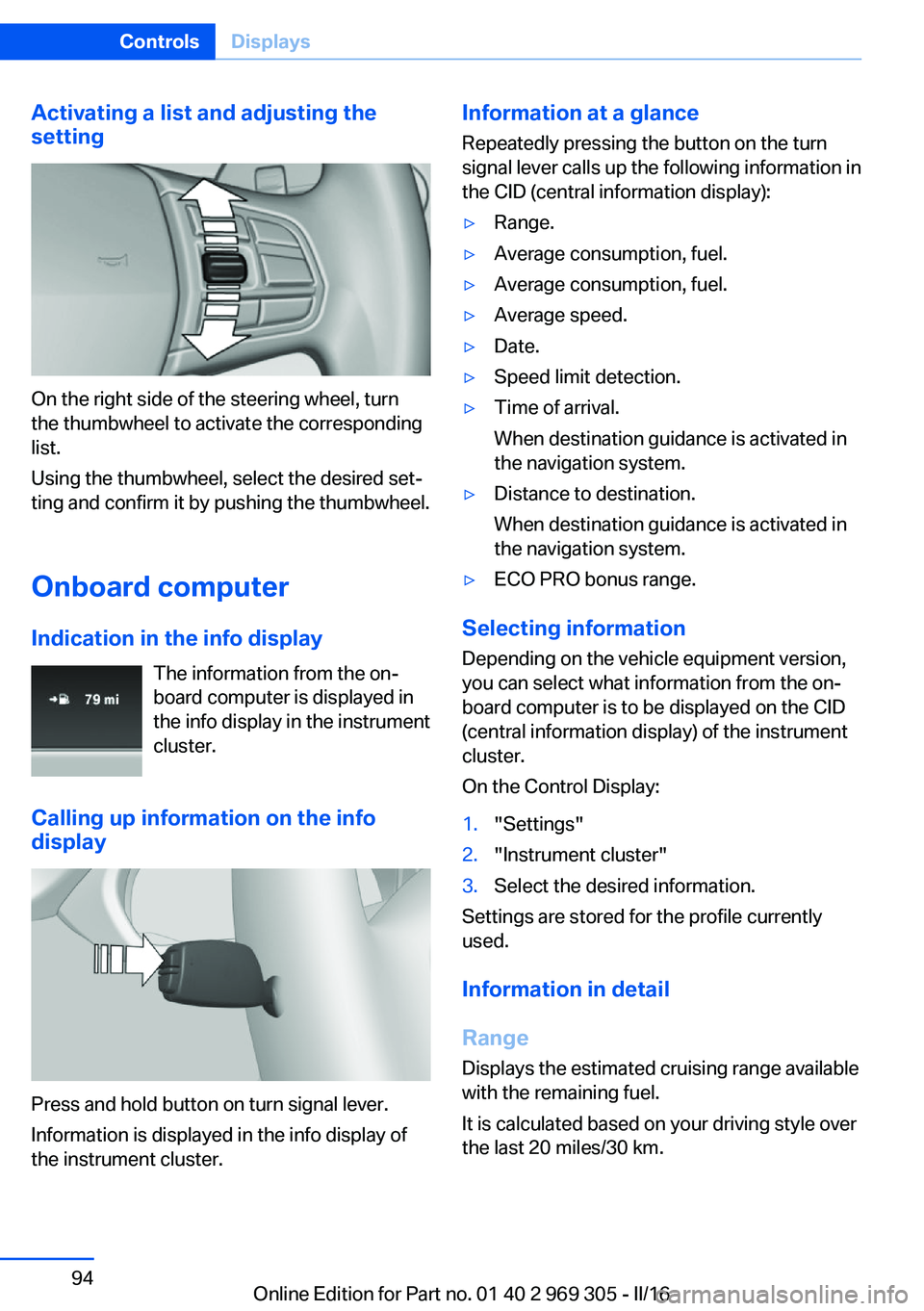
Activating a list and adjusting the
setting
On the right side of the steering wheel, turn
the thumbwheel to activate the corresponding
list.
Using the thumbwheel, select the desired set‐
ting and confirm it by pushing the thumbwheel.
Onboard computer
Indication in the info display The information from the on‐
board computer is displayed in
the info display in the instrument
cluster.
Calling up information on the info
display
Press and hold button on turn signal lever.
Information is displayed in the info display of
the instrument cluster.
Information at a glance
Repeatedly pressing the button on the turn
signal lever calls up the following information in
the CID (central information display):▷Range.▷Average consumption, fuel.▷Average consumption, fuel.▷Average speed.▷Date.▷Speed limit detection.▷Time of arrival.
When destination guidance is activated in
the navigation system.▷Distance to destination.
When destination guidance is activated in
the navigation system.▷ECO PRO bonus range.
Selecting information
Depending on the vehicle equipment version,
you can select what information from the on‐
board computer is to be displayed on the CID
(central information display) of the instrument
cluster.
On the Control Display:
1."Settings"2."Instrument cluster"3.Select the desired information.
Settings are stored for the profile currently
used.
Information in detail
Range
Displays the estimated cruising range available
with the remaining fuel.
It is calculated based on your driving style over
the last 20 miles/30 km.
Seite 94ControlsDisplays94
Online Edition for Part no. 01 40 2 969 305 - II/16