Page 105 of 128

Periodic maintenance and adjustment7-28
1
2
3
4
5
678
9
10
11
12
EAU23115
Checking and lubricating the
throttle grip and cableThe operation of the throttle grip should
be checked before each ride. In addi-
tion, the cable should be lubricated by a
Yamaha dealer at the intervals speci-
fied in the periodic maintenance chart.
The throttle cable is equipped with a
rubber cover. Make sure that the cover
is securely installed. Even though the
cover is installed correctly, it does not
completely protect the cable from water
entry. Therefore, use care not to pour
water directly onto the cover or cable
when washing the vehicle. If the cable
or cover becomes dirty, wipe clean with
a moist cloth.
EAU44276
Checking and lubr icating the
brake and shift pedalsThe operation of the brake and shift
pedals should be checked before each
ride, and the pedal pivots should be lu-
bricated if necessary.
Brake pedal Shift pedal
Recommended lubricant:
Lithium-soap-based grease
2CR-9-E1.book 28 ページ 2015年8月20日 木曜日 午後4時46分
Page 106 of 128
Periodic maintenance and adjustment
7-29
1
2
3
4
5
67
8
9
10
11
12
EAU23144
Checking and lubricating the
brake and clutch leversThe operation of the brake and clutch
levers should be checked before each
ride, and the lever pivots should be lu-
bricated if necessary.
Brake lever Clutch lever
EAU23203
Checking and lubricating the
sidestandThe operation of the sidestand should
be checked before each ride, and the
sidestand pivot and metal-to-metal
contact surfaces should be lubricated if
necessary.
WARNING
EWA10732
If the sidestand does not move up
and down smoothly, have a Yamaha
dealer check or repair it. Otherwise,
the sidestand could contact the
ground and distract the operator, re-sulting in a possible loss of control.
Recommended lubricants:
Brake lever:Silicone grease
Clutch lever: Lithium-soap-based grease
Recommended lubricant: Lithium-soap-based grease
2CR-9-E1.book 29 ページ 2015年8月20日 木曜日 午後4時46分
Page 107 of 128

Periodic maintenance and adjustment7-30
1
2
3
4
5
678
9
10
11
12
EAUM1653
Lubricating the swingarm
pivotsThe swingarm pivots must be lubricat-
ed by a Yamaha dealer at the intervals
specified in the periodic maintenance
and lubrication chart.
EAU23273
Checking the front forkThe condition and operation of the front
fork must be checked as follows at the
intervals specified in the periodic main-
tenance and lubrication chart.
To check the condition
Check the inner tubes for scratches,
damage and excessive oil leakage.
To check the operation 1. Place the vehicle on a level sur- face and hold it in an upright posi-
tion. WARNING! To avoid injury,
securely support the vehicle so
there is no danger of it falling
over.
[EWA10752]
2. While applying the front brake, push down hard on the handlebars
several times to check if the front
fork compresses and rebounds
smoothly.
NOTICE
ECA10591
If any damage is found or the front
fork does not operate smoothly,
have a Yamaha dealer check or re-pair it.
Recommended lubricant:Lithium-soap-based grease
2CR-9-E1.book 30 ページ 2015年8月20日 木曜日 午後4時46分
Page 108 of 128

Periodic maintenance and adjustment
7-31
1
2
3
4
5
67
8
9
10
11
12
EAU23285
Checking the steeringWorn or loose steering bearings may
cause danger. Therefore, the operation
of the steering must be checked as fol-
lows at the intervals specified in the pe-
riodic maintenance and lubrication
chart. 1. Raise the front wheel off the ground. (See page 7-36.)
WARNING! To avoid injury, se-
curely support the vehicle so
there is no danger of it falling
over.
[EWA10752]
2. Hold the lower ends of the frontfork legs and try to move them for-
ward and backward. If any free
play can be felt, have a Yamaha
dealer check or repair the steering.
EAU23292
Checking the w heel bearingsThe front and rear wheel bearings must
be checked at the intervals specified in
the periodic maintenance and lubrica-
tion chart. If there is play in the wheel
hub or if the wheel does not turn
smoothly, have a Yamaha dealer check
the wheel bearings.
EAU68230
BatteryNOTICE
ECA22960
Use only the specified genuine
YAMAHA battery. Using a different
battery may cause the IMU to fail andthe engine to stall.
The battery is located under the rider
seat. (See page 4-36.)NOTICE
ECA22970
The IMU is located under the battery.
It is not user serviceable and very
sensitive, so we advise against re-1. Positive battery lead (red)
2. Negative battery lead (black)
3. Battery
1
2
3
2CR-9-E1.book 31 ページ 2015年8月20日 木曜日 午後4時46分
Page 109 of 128

Periodic maintenance and adjustment7-32
1
2
3
4
5
678
9
10
11
12
moving the battery box or handling
the IMU directly.
Do not remove, modify, or place
any foreign materials in or
around the battery box.
Do not subject the IMU to strong
shocks and be careful when
handling the battery.
Do not obstruct the IMU breath-
er hole and do not clean it withcompressed air.
This model is equipped with a VRLA
(Valve Regulated Lead Acid) battery.
There is no need to check the electro-
lyte or to add distilled water. However,
the battery lead connections need to be
checked and, if necessary, tightened.WARNING
EWA10761
Electrolyte is poisonous and
dangerous since it contains sul-
furic acid, which causes severe
burns. Avoid any contact with
skin, eyes or clothing and al-
ways shield your eyes when
working near batteries. In case
of contact, administer the fol- lowing FIRST AID.
EXTERNAL: Flush with plenty
of water.
INTERNAL: Drink large quan- tities of water or milk and im-
mediately call a physician.
EYES: Flush with water for 15 minutes and seek prompt
medical attention.
Batteries produce explosive hy-
drogen gas. Therefore, keep
sparks, flames, cigarettes, etc.,
away from the battery and pro-
vide sufficient ventilation when
charging it in an enclosed
space.
KEEP THIS AND ALL BATTER-
IES OUT OF THE REACH OFCHILDREN.
To charge the battery
Have a Yamaha dealer charge the bat-
tery as soon as possible if it seems to
have discharged. Keep in mind that the
battery tends to discharge more quickly
if the vehicle is equipped with optional
electrical accessories.
NOTICE
ECA16522
To charge a VRLA (Valve Regulated
Lead Acid) battery, a special (con-
stant-voltage) battery charger is re-
quired. Using a conventional batterycharger will damage the battery.
To store the battery 1. If the vehicle will not be used for more than one month, remove the
battery, fully charge it, and then
place it in a cool, dry place.
NOTICE: When removing the
battery, be sure the key is
turned to “OFF”, then discon-
nect the negative lead before
disconnecting the positive
lead.
[ECA16303]
2. If the battery will be stored for more than two months, check it at least
once a month and fully charge it if
necessary.
3. Fully charge the battery before in- stallation. NOTICE: When install-
ing the battery, be sure the key
is turned to “OFF”, then con-
nect the positive lead before
2CR-9-E1.book 32 ページ 2015年8月20日 木曜日 午後4時46分
Page 110 of 128
Periodic maintenance and adjustment
7-33
1
2
3
4
5
67
8
9
10
11
12 connecting the negative
lead.
[ECA16841]
4. After installation, make sure that
the battery leads are properly con-
nected to the battery terminals.NOTICE
ECA16531
Always keep the battery charged.
Storing a discharged battery cancause permanent battery damage.
EAU66592
Replacing the fusesThe main fuse and ABS motor fuse are
located under the rider seat.
To access the ABS motor fuse1. Remove the passenger seat andrider seat. (See page 4-36.)
2. Remove the panel by removing the screws. 3. Remove the starter relay cover by
pulling it upward.
The fuse boxes, which contain the fus-
es for the individual circuits, are located
under panel A. (See page 7-8.)1. Main fuse
2. ABS motor fuse
3. Starter relay cover
4. ABS motor spare fuse1 2
4
3
1. Screw
2. Panel
1. Starter relay cover1
1
2
1
2CR-9-E1.book 33 ページ 2015年8月20日 木曜日 午後4時46分
Page 111 of 128

Periodic maintenance and adjustment7-34
1
2
3
4
5
678
9
10
11
12
If a fuse is blown, replace it as follows.
1. Turn the key to “OFF” and turn off the electrical circuit in question.
2. Remove the blown fuse, and then install a new fuse of the specified
amperage. WARNING! Do not
use a fuse of a higher amperage
rating than recommended to
avoid causing extensive dam-
age to the electrical system and
possibly a fire.
[EWA15132]
3. Turn the key to “ON” and turn on the electrical circuit in question to
1. Hazard fuse
2. Fuel injection system fuse
3. Electronic throttle valve fuse
4. Backup fuse
5. Sub radiator fan motor fuse
6. Radiator fan motor fuse
7. Spare fuse
1
2
3
4
5
6 7
1. Ignition fuse
2. Signaling system fuse
3. ABS ECU fuse
4. ABS solenoid fuse
5. Headlight fuse
6. Terminal fuse 1
7. Spare fuse
8. SCU fuse (YZF-R1M)
1
23
45
6
7
8
7
Specified fuses:
Main fuse:50.0 A
Terminal fuse 1:
2.0 A
Headlight fuse: 7.5 A
Signaling system fuse: 7.5 A
Ignition fuse:
15.0 A
Radiator fan motor fuse: 15.0 A
Sub radiator fan motor fuse: 10.0 A
ABS motor fuse:
30.0 A
Hazard fuse: 7.5 A
ABS ECU fuse: 7.5 A
ABS solenoid fuse:
15.0 A
SCU fuse: 7.5 A (YZF-R1M)
Fuel injection system fuse: 15.0 A
Backup fuse: 7.5 A
Electronic throttle valve fuse: 7.5 A
2CR-9-E1.book 34 ページ 2015年8月20日 木曜日 午後4時46分
Page 112 of 128
Periodic maintenance and adjustment
7-35
1
2
3
4
5
67
8
9
10
11
12 check if the device operates.
4. If the fuse immediately blows again, have a Yamaha dealer
check the electrical system.
EAU67121
Vehicle lightsThis model is equipped with full-LED
lighting.
The headlights, auxiliary lights, turn sig-
nals, tail/brake light, and license plate
light are all LED. There are no user re-
placeable bulbs.
If a light does not come on, check the
fuses and then have a Yamaha dealer
check the vehicle.NOTICE
ECA16581
Do not affix any type of tinted film orstickers to the headlight lens.
TIP
The right headlight comes on
when Pass/LAP switch “ /LAP”
is pushed or the dimmer switch is
set to “ ” (high beam).
The auxiliary lights were designed
to fade out as your R1 goes tosleep.
1. Auxiliary light
2. Headlight
12
1
2
2CR-9-E1.book 35 ページ 2015年8月20日 木曜日 午後4時46分
 1
1 2
2 3
3 4
4 5
5 6
6 7
7 8
8 9
9 10
10 11
11 12
12 13
13 14
14 15
15 16
16 17
17 18
18 19
19 20
20 21
21 22
22 23
23 24
24 25
25 26
26 27
27 28
28 29
29 30
30 31
31 32
32 33
33 34
34 35
35 36
36 37
37 38
38 39
39 40
40 41
41 42
42 43
43 44
44 45
45 46
46 47
47 48
48 49
49 50
50 51
51 52
52 53
53 54
54 55
55 56
56 57
57 58
58 59
59 60
60 61
61 62
62 63
63 64
64 65
65 66
66 67
67 68
68 69
69 70
70 71
71 72
72 73
73 74
74 75
75 76
76 77
77 78
78 79
79 80
80 81
81 82
82 83
83 84
84 85
85 86
86 87
87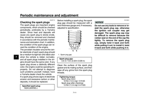 88
88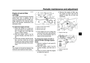 89
89 90
90 91
91 92
92 93
93 94
94 95
95 96
96 97
97 98
98 99
99 100
100 101
101 102
102 103
103 104
104 105
105 106
106 107
107 108
108 109
109 110
110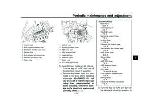 111
111 112
112 113
113 114
114 115
115 116
116 117
117 118
118 119
119 120
120 121
121 122
122 123
123 124
124 125
125 126
126 127
127
![YAMAHA YZF-R1M 2016 Owners Manual Periodic maintenance and adjustment
7-33
1
2
3
4
5
67
8
9
10
11
12 connecting the negative
lead.
[ECA16841]
4. After installation, make sure that
the battery leads are properly con-
nected to the batt](/manual-img/51/54106/w960_54106-109.png "YAMAHA YZF-R1M 2016 Owners Manual Periodic maintenance and adjustment
7-33
1
2
3
4
5
67
8
9
10
11
12 connecting the negative
lead.
[ECA16841]
4. After installation, make sure that
the battery leads are properly con-
nected to the batt")
