Page 25 of 88
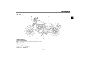
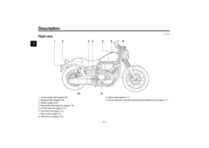
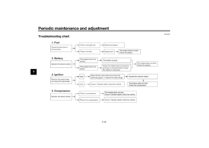
Instrument and control functions
3-10
3
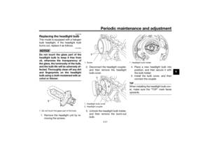
EAU12822
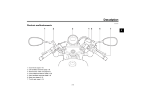
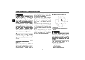
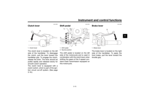
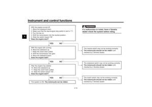
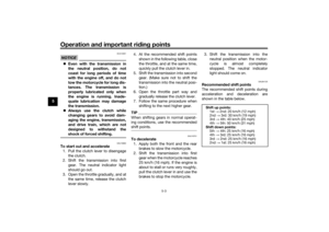
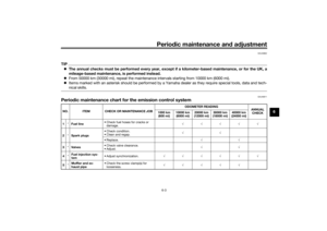
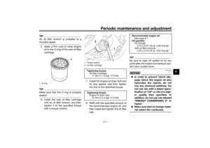
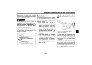
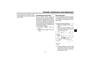
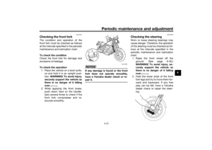
Clutch leverThe clutch lever is located on the left
side of the handlebar. To disengage
the clutch, pull the lever toward the
handlebar grip. To engage the clutch,
release the lever. The lever should be
pulled rapidly and released slowly for
smooth clutch operation.
The clutch lever is equipped with a
clutch switch, which is part of the igni-
tion circuit cut-off system. (See page
3-18.)
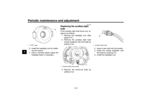
EAU12872
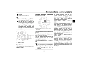
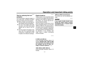
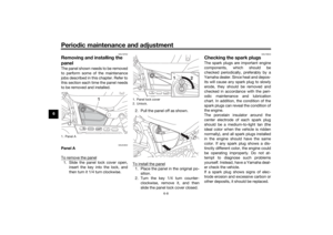
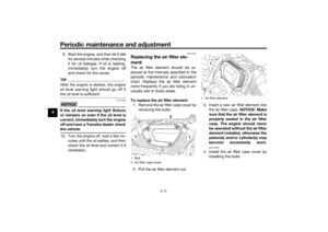
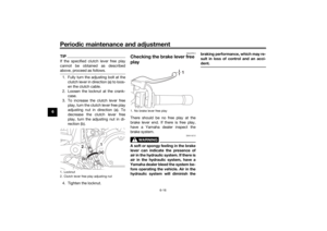
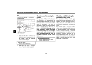
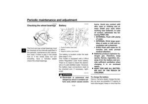
Shift pe dalThe shift pedal is located on the left
side of the motorcycle and is used in
combination with the clutch lever when
shifting the gears of the 5-speed con-
stant-mesh transmission equipped on
this motorcycle.
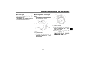
EAU12892
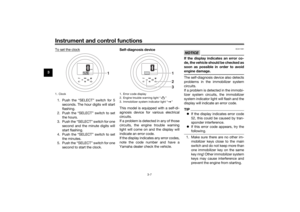
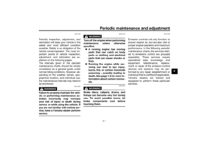
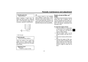
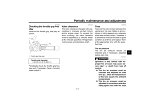
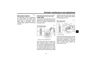
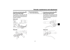
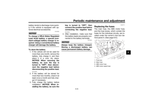
Brake leverThe brake lever is located on the right
side of the handlebar. To apply the
front brake, pull the lever toward the
throttle grip.
1. Clutch lever
1
1. Shift pedal
2. Neutral position
1
2
5
4
3
2
N 1 5
4
3
2
N 1
1. Brake lever
1
UB33E1E0.book Page 10 Wednesday, September 9, 2015 2:55 PM
Page 26 of 88

Instrument and control functions
3-11
3
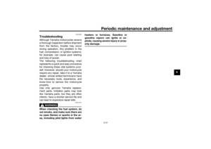
EAU12944
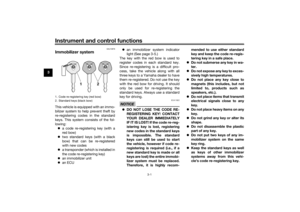
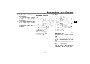
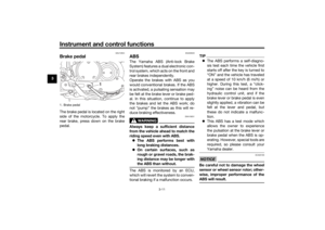
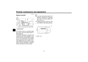
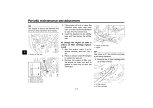
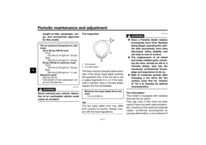
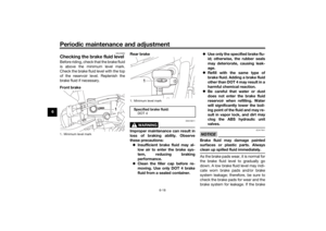
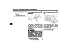
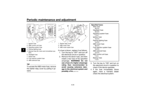
Brake ped alThe brake pedal is located on the right
side of the motorcycle. To apply the
rear brake, press down on the brake
pedal.
EAU63040
ABSThe Yamaha ABS (Anti-lock Brake
System) features a dual electronic con-
trol system, which acts on the front and
rear brakes independently.
Operate the brakes with ABS as you
would conventional brakes. If the ABS
is activated, a pulsating sensation may
be felt at the brake lever or brake ped-
al. In this situation, continue to apply
the brakes and let the ABS work; do
not “pump” the brakes as this will re-
duce braking effectiveness.
WARNING
EWA16051
Always keep a sufficient d istance
from the vehicle ahea d to match the
ri din g spee d even with ABS.
The ABS performs best with
lon g b rakin g d istances.
On certain surfaces, such as
rou gh or g ravel roa ds, the b rak-
in g d istance may b e longer with
the ABS than without.The ABS is monitored by an ECU,
which will revert the system to conven-
tional braking if a malfunction occurs.
TIP The ABS performs a self-diagno-
sis test each time the vehicle first
starts off after the key is turned to
“ON” and the vehicle has traveled
at a speed of 10 km/h (6 mi/h) or
higher. During this test, a “click-
ing” noise can be heard from the
hydraulic control unit, and if the
brake lever or brake pedal is even
slightly applied, a vibration can be
felt at the lever and pedal, but
these do not indicate a malfunc-
tion.
This ABS has a test mode which
allows the owner to experience
the pulsation at the brake lever or
brake pedal when the ABS is op-
erating. However, special tools are
required, so please consult your
Yamaha dealer.NOTICE
ECA20100
Be careful not to d amage the wheel
sensor or wheel sensor rotor; other-
wise, improper performance of the
ABS will result.
1. Brake pedal
1
UB33E1E0.book Page 11 Wednesday, September 9, 2015 2:55 PM
Page 27 of 88

Instrument and control functions
3-12
3
EAU13125
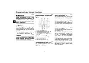
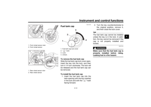
Fuel tank capTo remove the fuel tank cap
Slide the fuel tank cap lock cover open,
insert the key into the lock, and then
turn it 1/4 turn clockwise. The lock will
be released and the fuel tank cap can
be removed.
To install the fuel tank cap
1. Insert the fuel tank cap into the tank opening with the key inserted
in the lock and with the “ ” mark
facing forward. 2. Turn the key counterclockwise to
the original position, remove it,
and then close the lock cover.
TIPThe fuel tank cap cannot be installed
unless the key is in the lock. In addi-
tion, the key cannot be removed if the
cap is not properly installed and
locked.
WARNING
EWA10132
Make sure that the fuel tank cap is
properly installe d before ri din g.
Leakin g fuel is a fire hazar d.
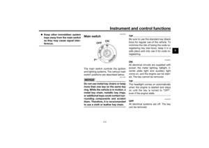
1. Front wheel sensor rotor
2. Front wheel sensor
1. Rear wheel sensor rotor
2. Rear wheel sensor1
21
2
1. Fuel tank cap lock cover
2. “ ” mark
3. Lock.
4. Unlock.1
2 4
3
UB33E1E0.book Page 12 Wednesday, September 9, 2015 2:55 PM
Page 28 of 88

Instrument and control functions
3-13
3
EAU13222
FuelMake sure there is sufficient gasoline in
the tank.
WARNING
EWA10882
Gasoline an d g asoline vapors are
extremely flammab le. To avoid fires
an d explosions an d to re duce the
risk of injury when refuelin g, follow
these instructions.1. Before refueling, turn off the en- gine and be sure that no one is sit-
ting on the vehicle. Never refuel
while smoking, or while in the vi-
cinity of sparks, open flames, or
other sources of ignition such as
the pilot lights of water heaters
and clothes dryers.
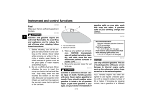
2. Do not overfill the fuel tank. When refueling, be sure to insert the
pump nozzle into the fuel tank filler
hole. Stop filling when the fuel
reaches the bottom of the filler
tube. Because fuel expands when
it heats up, heat from the engine or
the sun can cause fuel to spill out
of the fuel tank. 3. Wipe up any spilled fuel immedi-
ately. NOTICE: Immediately
wipe off spille d fuel with a clean,
d ry, soft cloth, since fuel may
d eteriorate painted surfaces or
plastic parts.
[ECA10072]
4. Be sure to securely close the fuel tank cap.
WARNING
EWA15152
Gasoline is poisonous an d can cau-
se injury or death. Han dle gasoline
with care. Never siphon gasoline by
mouth. If you shoul d swallow some
g asoline or inhale a lot of g asoline
vapor, or g et some gasoline in your
eyes, see your d octor immediately. If g
asoline spills on your skin, wash
with soap an d water. If gasoline
spills on your clothin g, chan ge your
clothes.
EAU57691
NOTICE
ECA11401
Use only unlea ded g asoline. The use
of lea ded g asoline will cause severe
d amag e to internal en gine parts,
such as the valves an d piston rin gs,
as well as to the exhaust system.Your Yamaha engine has been de-
signed to use regular unleaded gaso-
line with a research octane number of
95 or higher. If knocking (or pinging)
occurs, use a gasoline of a different
1. Fuel tank filler tube
2. Maximum fuel level
2
1
Recommen ded fuel:
Regular unleaded gasoline (Gasohol
[E10] acceptable)
Fuel tank capacity:
12 L (3.2 US gal, 2.6 Imp.gal)
Fuel reserve amount (when the fuel
level warnin g lig ht comes on):
2.8 L (0.74 US gal, 0.62 Imp.gal)
UB33E1E0.book Page 13 Wednesday, September 9, 2015 2:55 PM
Page 29 of 88

Instrument and control functions
3-14
3
brand or premium unleaded fuel. Use
of unleaded fuel will extend spark plug
life and reduce maintenance costs.
Gasohol
There are two types of gasohol: gaso-
hol containing ethanol and that con-
taining methanol. Gasohol containing
ethanol can be used if the ethanol con-
tent does not exceed 10% (E10). Gas-
ohol containing methanol is not
recommended by Yamaha because it
can cause damage to the fuel system
or vehicle performance problems.
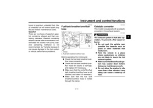
EAUB1302
Fuel tank
breather/overflow
hoseBefore operating the motorcycle:
Check the fuel tank breather/over-
flow hose connection.
Check the fuel tank breather/over-
flow hose for cracks or damage,
and replace it if necessary.
Make sure that the end of the fuel
tank breather/overflow hose is not
blocked, and clean it if necessary.
Make sure that the fuel tank
breather/overflow hose is routed
through the clamp.
EAU13434
Catalytic converterThis model is equipped with a catalytic
converter in the exhaust system.
WARNING
EWA10863
The exhaust system is hot after op-
eration. To prevent a fire hazar d or
b urns:
Do not park the vehicle near
possi ble fire hazar ds such as
g rass or other materials that
easily burn.
Park the vehicle in a place
where pe destrians or child ren
are not likely to touch the hot
exhaust system.
Make sure that the exhaust sys-
tem has coole d down before
d oin g any maintenance work.
Do not allow the en gine to i dle
more than a few minutes. Lon g
i d lin g can cause a b uild-up of
heat.
1. Clamp
2. Fuel tank brea ther/overflow hose
1
2
UB33E1E0.book Page 14 Wednesday, September 9, 2015 2:55 PM
Page 30 of 88
Instrument and control functions
3-15
3
NOTICE
ECA10702
Use only unlea ded g asoline. The use
of lead ed g asoline will cause unre-
pairab le damag e to the catalytic
converter.
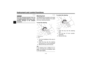
EAU55663
Steerin g lockThe steering lock is located on the right
side of the vehicle between the upper
and lower steering brackets.
To lock the steerin g
1. Turn the handlebar all the way to the left.
2. Insert the key into the steering lock and turn it 1/2 turn clockwise.
3. Remove the key from the lock.TIPIf the steering lock is difficult to en-
gage, try turning the handlebars back
to the right slightly.
To unlock the steerin g
1. Insert the key into the steering lock.
2. Turn the key 1/2 turn counter- clockwise.
3. Remove the key.
1. Steering lock
2. Lock.
LOCKUNLOCK
1
2
1. Unlock.
LOCKUNLOCK
1
UB33E1E0.book Page 15 Wednesday, September 9, 2015 2:55 PM
Page 31 of 88
Instrument and control functions
3-16
3
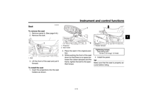
EAU66400
SeatTo remove the seat
1. Remove panel A. (See page 6-8.)
2. Remove the bolt.
3. Lift the front of the seat and pull it forward.
To install the seat 1. Insert the projections into the seat holders as shown. 2. Place the seat in the original posi-
tion.
3. While pushing the front of the seat down so that there is no space be-
tween the rubber dampers and the
frame, tighten the bolt to the spec-
ified torque. 4. Install the panel.
TIPMake sure that the seat is properly se-
cured before riding.
1. Bolt
1
1. Projection
2. Seat holder
1
2
1. Rubber damper
Ti
ghtenin g torque:
Seat fitting bolt: 16 Nm (1.6 m·kgf, 12 ft·lbf)1
UB33E1E0.book Page 16 Wednesday, September 9, 2015 2:55 PM
Page 32 of 88

Instrument and control functions
3-17
3
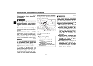
EAU66950
A djustin g the shock a bsorb er
assemb lies
WARNING
EWA10211
Always a djust both shock ab sorber
assem blies equally, otherwise poor
han dlin g an d loss of sta bility may re-
sult.Each shock absorber assembly is
equipped with a spring preload adjust-
ing ring.
It is recommended to have a Yamaha
dealer adjust the spring preload. How-
ever, if you choose to make this adjust-
ment yourself, obtain the special
wrench necessary at a Yamaha dealer.NOTICE
ECA10102
To avoi d d amag ing the mechanism,
d o not attempt to turn b eyond the
maximum or minimum setting s.Adjust the spring preload as follows.
To increase the spring preload and
thereby harden the suspension, turn
the adjusting ring on each shock ab-
sorber assembly in direction (a). To de-
crease the spring preload and thereby soften the suspension, turn the adjust-
ing ring on each shock absorber as-
sembly in direction (b).
WARNING
EWA10232
These shock ab
sorber assem blies
contain hi ghly pressurize d nitro gen
g as. Rea d an d und erstan d the fol-
lowin g information b efore handlin g
the shock a bsor ber assem blies.
Do not tamper with or attempt
to open the cylin der assem blies.
Do not su bject the shock a b-
sor ber assem blies to an open
flame or other hi gh heat source.
This may cause the unit to ex-
plo de due to excessive gas
pressure.
Do not deform or d amage the
cylin ders in any way. Cylin der
d amag e will result in poor
d ampin g performance.
Do not d ispose of a damag ed or
worn-out shock a bsor ber as-
sem bly
yourself. Take the shock
a b sor ber assem bly to a Yamaha
d ealer for any service.
1. Special wrench
2. Spring preload adjusting ring
3. StopperSprin g preloa d setting :
Minimum (soft):
0 notch(es) in direction (a)*
Standard: 1 notch(es) in direction (a)*
Maximum (hard): 4 notch(es) in direction (a)*
* With the adjusting ring fully turned
in direction (b)
2
(a)
(b)
1
3
UB33E1E0.book Page 17 Wednesday, September 9, 2015 2:55 PM


2. Remove the bolt.
3. Lift the front of the seat and pull it forward.
To install the seat 1.")