Page 49 of 90

Periodic maintenance an d a djustment
7-6
7
EAU19614
Checkin g the spark plu g
The spark plug is an important engine
component, which is easy to check.
Since heat and deposits will cause any
spark plug to slowly erode, the spark
plug should be removed and checked
in accordance with the periodic main-
tenance and lubrication chart. In addi-
tion, the condition of the spark plug
can reveal the condition of the engine.
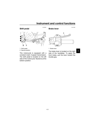
To remove the spark plu g
1. Remove the spark plug cap.
2. Remove the spark plug as shown, with a spark plug wrench available
at a Yamaha dealer. To check the spark plu
g
1. Check that the porcelain insulator around the center electrode of the
spark plug is a medium-to-light
tan (the ideal color when the vehi-
cle is ridden normally).
TIP
If the spark plug shows a distinctly dif-
ferent color, the engine could be oper-
ating improperly. Do not attempt to
diagnose such problems yourself. In-
stead, have a Yamaha dealer check
the vehicle.
2. Check the spark plug for electrodeerosion and excessive carbon or
other deposits, and replace it if
necessary.
3. Measure the spark plug gap with a wire thickness gauge and, if nec-
essary, adjust the gap to specifi-
cation.
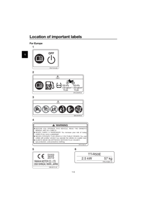
1. Spark plug cap
1. Spark plug wrench
Specified spark plu g:
NGK/CR7HSA
1. Spark plug gap
Spark plu g g ap:
0.6–0.7 mm (0.024–0.028 in)
U2CJ83E0.book Page 6 Friday, June 26, 2015 10:36 AM
Page 50 of 90

Periodic maintenance an d a djustment
7-7
7 To install the spark plu
g
1. Clean the surface of the spark plug gasket and its mating surfa-
ce, and then wipe off any grime
from the spark plug threads.
2. Install the spark plug with the spark plug wrench, and then tight-
en it to the specified torque.
TIP
If a torque wrench is not available
when installing a spark plug, a good
estimate of the correct torque is 1/4–
1/2 turn past finger tight. However, the
spark plug should be tightened to the
specified torque as soon as possible.
3. Install the spark plug cap.
EAU49934
Engine oil
The engine oil level should be checked
before each ride. In addition, the oil
must be changed at the intervals spec-
ified in the periodic maintenance and
lubrication chart.
To check the en gine oil level
1. Place the motorcycle on a level surface and hold it in an upright
position. A slight tilt to the side can
result in a false reading.
2. Start the engine, warm it up for several minutes, and then turn it
off.
3. Wait a few minutes until the oil set- tles, remove the engine oil filler
cap, wipe the engine oil dipstick
clean, insert it back into the oil filler
hole (without screwing it in), and
then remove it again to check the
oil level.
TIP
The engine oil should be between the
minimum and maximum level marks.
Tightenin g torque:
Spark plug: 13 Nm (1.3 m·kgf, 9.4 ft·lbf)
1. Engine oil filler cap
2. Engine oil dipstick
3. Maximum level mark
4. Minimum level mark
U2CJ83E0.book Page 7 Friday, June 26, 2015 10:36 AM
Page 51 of 90

Periodic maintenance an d a djustment
7-8
7
4. If the engine oil is at or below the
minimum level mark, add suffi-
cient oil of the recommended type
to raise it to the correct level.
5. Insert the dipstick into the oil filler hole, and then tighten the oil filler
cap.
To chan ge the en gine oil
1. Start the engine, warm it up for several minutes, and then turn it
off.
2. Place an oil pan under the engine to collect the used oil.
3. Remove the engine oil filler cap, the engine oil drain bolt and its
gasket to drain the oil from the
crankcase.
4. Install a new gasket and the drain bolt, and then tighten the drain
bolt to the specified torque.
5. Refill with the specified amount of the recommended engine oil, and
then install and tighten the oil filler
cap.
NOTICE
ECA11621
In or der to prevent clutch slip-
pa ge (since the en gine oil also
lu bricates the clutch), do not
mix any chemical additives. Do
not use oils with a diesel speci-
fication of “CD” or oils of a hi gh-
er quality than specified . In
a dd ition, do not use oils la bele d
“ENERGY CONSERVING II” or
hi gher.
Make sure that no forei gn mate-
rial enters the crankcase.
6. Start the engine, and then let it idle for several minutes while checking
it for oil leakage. If oil is leaking,
immediately turn the engine off
and check for the cause.
7. Turn the engine off, and then check the oil level and correct it if
necessary.
1. Engine oil drain bolt
2. Gasket
Tightening torque:
Engine oil drain bolt: 20 Nm (2.0 m·kgf, 14 ft·lbf)
12
Recommen ded en gine oil:
See page 9-1.
Oil chan ge quantity:
0.80 L (0.85 US qt, 0.70 Imp.qt)
U2CJ83E0.book Page 8 Friday, June 26, 2015 10:36 AM
Page 52 of 90

Periodic maintenance an d a djustment
7-9
7
EAU39835
Cleanin g the air filter element
The air filter element should be cleaned
as follows at the intervals specified in
the periodic maintenance and lubrica-
tion chart. Clean or, if necessary, re-
place the air filter element more
frequently if you are riding in unusually
wet or dusty areas.
To clean the air filter element
1. Remove the air filter case cover by removing the screws.
2. Pull the sponge material and the air filter mesh out. 3. Clean the mesh with solvent, and
then wipe the solvent off.
4. Clean the sponge material with solvent, and then squeeze the re-
maining solvent out. WARNING!
Use only a ded icated parts
cleanin g solvent. To avoi d the
risk of fire or explosion, do not
use gasoline or solvents with a
low flash point.
[EWA10432] NOTICE:
To avoi d damag ing the foam
material, han dle it g ently an d
carefully, an d d o not twist or
wrin g it.
[ECA10512]
5. Apply oil of the recommended
type to the entire surface of the
sponge material, and then
squeeze the excess oil out.
TIP
The sponge material should be wet but
not dripping.
1. Screw
2. Air filter case cover
1. Sponge material
1. Air filter mesh
U2CJ83E0.book Page 9 Friday, June 26, 2015 10:36 AM
Page 53 of 90

Periodic maintenance an d a djustment
7-10
7
6. Insert the mesh and the sponge
material into the air filter case.
NOTICE: Make sure that the
mesh an d the spon ge material
are properly seated in the air fil-
ter case. The en gine shoul d
never be operated without the
mesh an d the spon ge material
installe d, otherwise the pis-
ton(s) an d/or cylin der(s) may b e-
come excessively worn.
[ECA15573]
7. Install the air filter case cover by installing the screws.
To clean the air filter check hose 1. Check the hose at the bottom of the air filter case for accumulated
dirt or water.
2. If dirt or water is visible, remove the hose, clean it, and then install
it.
EAU40422
Cleanin g the spark arrester
The spark arrester should be cleaned
at the intervals specified in the periodic
maintenance and lubrication chart.
WARNING
EWA10981
Always let the exhaust system
cool prior to touching exhaust
components.
Do not start the en gine when
cleanin g the exhaust system.
TIP
Make sure to select a well-ventilated
area free of combustible materials to
clean the spark arrester.
1. Remove the tailpipe by removing
the bolts, and then pulling it out of
the muffler.
2. Tap the tailpipe lightly, and then use a wire brush to remove any
carbon deposits from the spark
arrester portion of the tailpipe and
inside of the tailpipe housing.
Recommen ded oil:
Yamaha foam air filter oil or other
quality foam air filter oil
1. Air filter check hose
1. Tailpipe bolt
2. Tailpipe
U2CJ83E0.book Page 10 Friday, June 26, 2015 10:36 AM
Page 54 of 90
Periodic maintenance an d a djustment
7-11
7 3. Insert the tailpipe into the muffler,
and then install and tighten the
bolts to the specified torque.
TIP
Make sure to align the bolt holes when
inserting the tailpipe.
EAU39931
Adjustin g the car buretor
The carburetor is an important part of
the engine and requires very sophisti-
cated adjustment. Therefore, most
carburetor adjustments should be left
to a Yamaha dealer, who has the nec-
essary professional knowledge and ex-
perience. The adjustment described in
the following section, however, may be
serviced by the owner as part of rou-
tine maintenance.
NOTICE
ECA10551
The car buretor has been set an d ex-
tensively teste d at the Yamaha fac-
tory. Chan gin g these settin gs
without sufficient technical knowl-
e dge may result in poor perfor-
mance of or d amage to the en gine.
1. Spark arrester
Ti ghtenin g torque:
Tailpipe bolt: 10 Nm (1.0 m·kgf, 7.2 ft·lbf)
1
U2CJ83E0.book Page 11 Friday, June 26, 2015 10:36 AM
Page 55 of 90

Periodic maintenance an d a djustment
7-12
7
EAU21363
A djustin g the eng ine idlin g
spee d
The engine idling speed must be
checked and, if necessary, adjusted as
follows at the intervals specified in the
periodic maintenance and lubrication
chart.
TIP
A diagnostic tachometer is needed to
make this adjustment.
1. Attach the tachometer to the
spark plug lead.
2. Start the engine and warm it up for several minutes at 1000–2000
r/min while occasionally revving it
to 4000–5000 r/min.
TIP
The engine is warm when it quickly re-
sponds to the throttle.
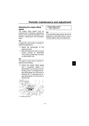
3. Check the engine idling speedand, if necessary, adjust it to
specification by turning the throt-
tle stop screw. To increase the en-
gine idling speed, turn the screw in
direction (a). To decrease the en-
gine idling speed, turn the screw in
direction (b).
TIP
If the specified idling speed cannot be
obtained as described above, have a
Yamaha dealer make the adjustment.
1. Throttle stop screw
(a)(b)
1
En gine i dlin g spee d:
1600–1800 r/min
U2CJ83E0.book Page 12 Friday, June 26, 2015 10:36 AM
Page 56 of 90
Periodic maintenance an d a djustment
7-13
7
EAU21385
Checkin g the throttle grip free
play
The throttle grip free play should mea-
sure 3.0–5.0 mm (0.12–0.20 in) at the
inner edge of the throttle grip. Periodi-
cally check the throttle grip free play
and, if necessary, have a Yamaha deal-
er adjust it.
EAU21402
Valve clearance
The valve clearance changes with use,
resulting in improper air-fuel mixture
and/or engine noise. To prevent this
from occurring, the valve clearance
must be adjusted by a Yamaha dealer
at the intervals specified in the periodic
maintenance and lubrication chart.
1. Throttle grip free play
1
U2CJ83E0.book Page 13 Friday, June 26, 2015 10:36 AM


 at the
inner edge of the thrott")