Page 33 of 110

Instrument and control functions
4-12
1
2
345
6
7
8
9
10
11
12
Transmission gear display
This display shows the selected gear.
The neutral position is indicated by “N”
and by the neutral indicator light.
Drive mode display
This display indicates which drive
mode has been selected: “STD”, “A” or
“B”. For more details on the modes and
on how to select them, see page 3-3.
TCS display
This display indicates which traction
control system setting has been select-
ed: “1”, “2”, “3” or “OFF”. For more de-
tails on the TCS settings and on how to
select them, see page 3-4.Multi-function display
The multi-function display is equipped
with the following:
an odometer (which shows the to-
tal distance traveled.)
two tripmeters (which show the
distance traveled since they were
last reset)
a fuel reserve tripmeter (which
shows the distanc
e traveled since
the last segment of the fuel meter
started flashing)
an instantaneous fuel consump-
tion display
an average fuel consumption dis-
play
a display brightness and shift tim-
1. Neutral indicator light “ ”
2. Transmission gear display
1. Drive mode display12
1
1. TCS display
1
1. Multi-function display
1
B67-9-E0.book 12 ページ 2016年2月29日 月曜日 午前9時30分
Page 34 of 110

Instrument and control functions
4-13
1
2
34
5
6
7
8
9
10
11
12 ing indicator light control display
TIP
The odometer will lock at 999999.
The tripmeters reset and continuecounting after 9999.9 is reached.
Push the select switch “SELECT” to
switch the display between the odome-
ter mode “ODO”, tripmeter modes
“TRIP 1” and “TRIP 2”, instantaneous
fuel consumption mode “km/L” or
“L/100 km”, average fuel consumption
mode “AVE – –.– km/L” or “AVE – –.–
L/100 km” in the following order:
ODO TRIP 1 TRIP 2 km/L or
L/100 km AVE – –.– km/L or AVE – –.– L/100 km
ODO
For the UK:
Push the select switch “SELECT” for
one second to switch the display be-
tween the odometer mode “ODO”, trip-
meter modes “TRIP 1” and “TRIP 2”,
instantaneous fuel consumption mode
“km/L”, “L/100 km” or “MPG”, average
fuel consumption mode “AVE – –.–
km/L”, “AVE – –.– L/100 km” or “AVE –
–.– MPG” in the following order:
ODO TRIP 1 TRIP 2 km/L,
L/100 km or MPG AVE – –.– km/L,
AVE – –.– L/100 km or AVE – –.– MPG
ODO
TIPThe fuel reserve tripmeter comes onautomatically.
If the last segment of the fuel meter
starts flashing, the display automatical-
ly changes to the fuel reserve tripmeter
mode “TRIP F” and starts counting the
distance traveled from that point. In this
case, push the “SELECT” switch to
switch the display in the following order: TRIP F
km/L or L/100 km AVE –
–.– km/L or AVE – –.– L/100 km
ODO TRIP 1 TRIP 2 TRIP F
For the UK:
TRIP F km/L, L/100 km or MPG
AVE – –.– km/L, AVE – –.– L/100 km or
AVE – –.– MPG ODO TRIP 1
TRIP 2 TRIP F
TIP
To reset a tripmeter, select it by
pushing the “SELECT” switch, and
then push the “RESET” button for
two seconds.
If you do not reset the fuel reserve
tripmeter manually, it resets auto-
matically and disappears after re-fueling and traveling 5 km (3 mi).
1. Select switch “SELECT”
RESSE T
PAS
S
TCS
SELECT
1
B67-9-E0.book 13 ページ 2016年2月29日 月曜日 午前9時30分
Page 35 of 110

Instrument and control functions
4-14
1
2
345
6
7
8
9
10
11
12
Instantaneous fuel consumption
mode
The instantaneous fuel consumption
display can be set to either “km/L”,
“L/100 km” or “MPG” (for the UK).
“km/L”: The distance that can be
traveled on 1.0 L of fuel under the
current riding conditions is shown.
“L/100 km”: The amount of fuel
necessary to travel 100 km under
the current riding conditions is
shown.
“MPG” (for the UK): The distance
that can be traveled on 1.0 Imp.gal
of fuel under the current riding con-
ditions is shown.
To switch between the instantaneous fuel consumption display settings, push
the “CLOCK” and “RESET” button to-
gether.
TIPIf traveling at speeds under 20 km/h (12mi/h), “– –.–” is displayed.
Average fuel consumption mode
This display shows the average fuel
consumption since it was last reset.
The average fuel consumption display
can be set to either “AVE – –.– km/L”,
“AVE – –.– L/100 km” or “AVE – –.–
MPG” (for the UK).
“AVE – –.– km/L”: The average
distance that can be traveled on1.0 L of fuel is shown.
“AVE – –.– L/100 km”: The aver-
age amount of fuel necessary to
travel 100 km is shown.
“AVE – –.– MPG” (for the UK): The
average distance that can be trav-
eled on 1.0 Imp.gal of fuel is
shown.
To switch between the average fuel
consumption display settings, push the
“CLOCK” and “RESET” button togeth-
er.
To reset the average fuel consumption,
push the “RESET” button for two sec-
onds.
TIPAfter resetting the average fuel con-
sumption, “– –.–” will be shown until thevehicle has traveled 1 km (0.6 mi).
1. Instantaneous fuel consumption display
1
1. Average fuel consumption display
1
B67-9-E0.book 14 ページ 2016年2月29日 月曜日 午前9時30分
Page 36 of 110

Instrument and control functions
4-15
1
2
34
5
6
7
8
9
10
11
12 Display brightness and shift timing
indicator light control mode
This mode cycles through five control
functions, allowing you to make the fol-
lowing settings in the order listed be-
low.
Display brightness:
This function allows you to adjust
the brightness of the displays and
tachometer.
Shift timing indicator light activity
function:
This function allows you to set the
indicator light to on, flash, or off.
Shift timing indicator light activa-
tion:
This function allows you to select the engine speed at which the indi-
cator light will be activated.
Shift timing indica
tor light deactiva-
tion:
This function allows you to select
the engine speed at which the indi-
cator light will be deactivated.
Shift timing indicator light bright-
ness:
This function allows you to adjust
the brightness of the shift timing in-
dicator light.
TIPThe brightness level display shows thebrightness level setting.
To adjust the brightness of the displaysand tachometer1. Turn the key to “OFF”.
2. Push and hold the “CLOCK” but- ton.
3. Turn the key to “ON”, and then re- lease the “CLOCK” button after
five seconds.
4. Push the “RESET” button to select the desired brightness level.
5. Push the “CLOCK” button to con- firm the selected brightness level. The control mode changes to the
shift timing indicator light activity
function.
To set the shift timing indicator light ac-
tivity function1. Push the “RESET” button to select one of the following indicator light
activity settings:
On - the indicator light will come
on when activated. (This setting
is selected when the indicator
light stays on.)
Flash - the indicator light will
flash when activated. (This set-
ting is selected when the indica-
tor light flashes four times per
second.)
Off - the indicator light is deacti-
vated; in other words, it will not
come on or flash. (This setting
is selected when the indicator
light flashes once every two
seconds.)
2. Push the “CLOCK” button to con- firm the selected indicator light ac-
tivity. The control mode changes to
the shift timing indicator light acti-
vation function.
1. Brightness level display
1
B67-9-E0.book 15 ページ 2016年2月29日 月曜日 午前9時30分
Page 37 of 110

Instrument and control functions
4-16
1
2
345
6
7
8
9
10
11
12
To set the shift timing indicator light ac-
tivation functionTIPThe shift timing indicator light activation
function can be set between 7000 r/min
and 13000 r/min. The indicator light canbe set in increments of 200 r/min.
1. Push the “RESET” button to select the desired engine speed for acti-
vating the indicator light.
2. Push the “CLOCK” button to con- firm the selected engine speed.
The control mode changes to the
shift timing indicator light deactiva-
tion function.
To set the shift timing indicator light de-activation functionTIP
The shift timing indicator light de-
activation function can be set be-
tween 7000 r/min and 13000 r/min.
The indicator light can be set in in-
crements of 200 r/min.
Be sure to set the deactivation
function to a higher engine speed
than for the activation function,
otherwise the shift timing indicator
light will remain deactivated.
1. Push the “RESET” button to select the desired engine speed for deac-
tivating the indicator light.
2. Push the “CLOCK” button to con- firm the selected engine speed.
The control mode changes to the
shift timing indicator light bright-
ness function.
To adjust the shift timing indicator light
brightness1. Push the “RESET” button to select the desired indicator light bright-
ness level.
2. Push the “CLOCK” button to con- firm the selected indicator light
brightness level and exit the dis-
play brightness and shift timing in-
dicator light control mode.
EAU12822
Clutch leverThe clutch lever is located on the left
side of the handlebar. To disengage
the clutch, pull the lever toward the
handlebar grip. To engage the clutch,
release the lever. The lever should be
pulled rapidly and released slowly for
smooth clutch operation.
The clutch lever is equipped with a
clutch switch, which is part of the igni-
tion circuit cut-off system. (See
page 4-29.)1. Clutch lever
1
B67-9-E0.book 16 ページ 2016年2月29日 月曜日 午前9時30分
Page 38 of 110
Instrument and control functions
4-17
1
2
34
5
6
7
8
9
10
11
12
EAU12872
Shift pedalThe shift pedal is located on the left
side of the motorcycle and is used in
combination with the clutch lever when
shifting the gears of the 6-speed con-
stant-mesh transmission equipped on
this motorcycle.
EAU26825
Brake leverThe brake lever is located on the right
side of the handlebar. To apply the front
brake, pull the lever toward the throttle
grip.
The brake lever is equipped with a
brake lever position adjusting dial. To
adjust the distance between the brake
lever and the throttle grip, turn the ad-
justing dial while holding the lever
pushed away from the throttle grip.
Make sure that the appropriate setting
on the adjusting dial is aligned with the “ ” mark on the brake lever.
1. Shift pedal
1
1. “ ” mark
2. Brake lever position adjusting dial
3. Brake lever
4. Distance between brake lever and throttle
grip
4
1 2
3
B67-9-E0.book 17 ページ 2016年2月29日 月曜日 午前9時30分
Page 39 of 110

Instrument and control functions
4-18
1
2
345
6
7
8
9
10
11
12
EAU12944
Brake pedalThe brake pedal is located on the right
side of the motorcycle. To apply the
rear brake, press down on the brake
pedal.
EAU63040
ABSThe Yamaha ABS (Anti-lock Brake
System) features a dual electronic con-
trol system, which acts on the front and
rear brakes independently.
Operate the brakes with ABS as you
would conventional br akes. If the ABS
is activated, a pulsating sensation may
be felt at the brake lever or brake pedal.
In this situation, continue to apply the
brakes and let the ABS work; do not
“pump” the brakes as this will reduce
braking effectiveness.
WARNING
EWA16051
Always keep a sufficient distance
from the vehicle ahead to match the
riding speed even with ABS.
The ABS performs best with
long braking distances.
On certain surfaces, such as
rough or gravel roads, the brak-
ing distance may be longer withthe ABS than without.
The ABS is monitored by an ECU,
which will revert the system to conven-
tional braking if a malfunction occurs.
TIP
The ABS performs a self-diagno-
sis test each time the vehicle first
starts off after the key is turned to
“ON” and the vehicle has traveled
at a speed of 10 km/h (6 mi/h) or
higher. During this test, a “clicking”
noise can be heard from the hy-
draulic control unit, and if the brake
lever or brake pedal is even slight-
ly applied, a vibration can be felt at
the lever and pedal, but these do
not indicate a malfunction.
This ABS has a test mode which
allows the owner to experience the
pulsation at the brake lever or
brake pedal when the ABS is oper-
ating. However, special tools are
required, so please consult yourYamaha dealer.
NOTICE
ECA20100
Be careful not to damage the wheel
sensor or wheel sensor rotor; other-
wise, improper performance of theABS will result.
1. Brake pedal
1
B67-9-E0.book 18 ページ 2016年2月29日 月曜日 午前9時30分
Page 40 of 110
Instrument and control functions
4-19
1
2
34
5
6
7
8
9
10
11
12
EAU13075
Fuel tank capTo open the fuel tank cap
Open the fuel tank cap lock cover, in-
sert the key into the lock, and then turn
it 1/4 turn clockwise. The lock will be re-
leased and the fuel tank cap can be
opened.
To close the fuel tank cap 1. Push the fuel tank cap into position with the key inserted in the lock.
2. Turn the key counterclockwise to the original position, remove it, and
then close the lock cover.
TIPThe fuel tank cap cannot be closed un-
less the key is in the lock. In addition,
the key cannot be removed if the cap isnot properly closed and locked.
WARNING
EWA11092
Make sure that the fuel tank cap is
properly closed after filling fuel.Leaking fuel is a fire hazard.
1. Front wheel sensor rotor
2. Front wheel sensor
1. Rear wheel sensor rotor
2. Rear wheel sensor
2
12
1
1. Fuel tank cap lock cover
2. Unlock.
1
2
B67-9-E0.book 19 ページ 2016年2月29日 月曜日 午前9時30分
 1
1 2
2 3
3 4
4 5
5 6
6 7
7 8
8 9
9 10
10 11
11 12
12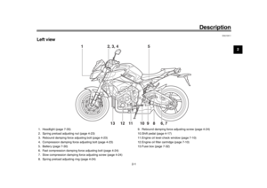 13
13 14
14 15
15 16
16 17
17 18
18 19
19 20
20 21
21 22
22 23
23 24
24 25
25 26
26 27
27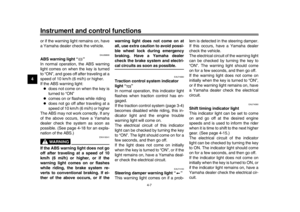 28
28 29
29 30
30 31
31 32
32 33
33 34
34 35
35 36
36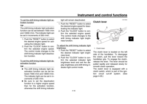 37
37 38
38 39
39 40
40 41
41 42
42 43
43 44
44 45
45 46
46 47
47 48
48 49
49 50
50 51
51 52
52 53
53 54
54 55
55 56
56 57
57 58
58 59
59 60
60 61
61 62
62 63
63 64
64 65
65 66
66 67
67 68
68 69
69 70
70 71
71 72
72 73
73 74
74 75
75 76
76 77
77 78
78 79
79 80
80 81
81 82
82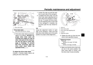 83
83 84
84 85
85 86
86 87
87 88
88 89
89 90
90 91
91 92
92 93
93 94
94 95
95 96
96 97
97 98
98 99
99 100
100 101
101 102
102 103
103 104
104 105
105 106
106 107
107 108
108 109
109
